US10697219B2 - Tensioners for movable partition systems, movable partition systems including such tensioners, and related methods - Google Patents
Tensioners for movable partition systems, movable partition systems including such tensioners, and related methods Download PDFInfo
- Publication number
- US10697219B2 US10697219B2 US15/676,538 US201715676538A US10697219B2 US 10697219 B2 US10697219 B2 US 10697219B2 US 201715676538 A US201715676538 A US 201715676538A US 10697219 B2 US10697219 B2 US 10697219B2
- Authority
- US
- United States
- Prior art keywords
- endplate
- bracket
- chain
- movable partition
- belt
- Prior art date
- Legal status (The legal status is an assumption and is not a legal conclusion. Google has not performed a legal analysis and makes no representation as to the accuracy of the status listed.)
- Active, expires
Links
- 238000005192 partition Methods 0.000 title claims abstract description 136
- 238000000034 method Methods 0.000 title claims abstract description 15
- 230000007246 mechanism Effects 0.000 claims abstract description 53
- 238000009434 installation Methods 0.000 abstract description 3
- 230000004888 barrier function Effects 0.000 description 17
- 230000003247 decreasing effect Effects 0.000 description 5
- 230000000295 complement effect Effects 0.000 description 3
- 239000000853 adhesive Substances 0.000 description 2
- 230000001070 adhesive effect Effects 0.000 description 2
- 239000000919 ceramic Substances 0.000 description 2
- 239000000463 material Substances 0.000 description 2
- 239000002184 metal Substances 0.000 description 2
- 230000004048 modification Effects 0.000 description 2
- 238000012986 modification Methods 0.000 description 2
- 239000004033 plastic Substances 0.000 description 2
- 239000000779 smoke Substances 0.000 description 2
- 239000002023 wood Substances 0.000 description 2
- 230000000694 effects Effects 0.000 description 1
- 239000012212 insulator Substances 0.000 description 1
- 230000007257 malfunction Effects 0.000 description 1
- 238000004519 manufacturing process Methods 0.000 description 1
- 238000000638 solvent extraction Methods 0.000 description 1
Images


Classifications
-
- E—FIXED CONSTRUCTIONS
- E05—LOCKS; KEYS; WINDOW OR DOOR FITTINGS; SAFES
- E05D—HINGES OR SUSPENSION DEVICES FOR DOORS, WINDOWS OR WINGS
- E05D15/00—Suspension arrangements for wings
- E05D15/06—Suspension arrangements for wings for wings sliding horizontally more or less in their own plane
- E05D15/12—Suspension arrangements for wings for wings sliding horizontally more or less in their own plane consisting of parts connected at their edges
-
- E—FIXED CONSTRUCTIONS
- E05—LOCKS; KEYS; WINDOW OR DOOR FITTINGS; SAFES
- E05F—DEVICES FOR MOVING WINGS INTO OPEN OR CLOSED POSITION; CHECKS FOR WINGS; WING FITTINGS NOT OTHERWISE PROVIDED FOR, CONCERNED WITH THE FUNCTIONING OF THE WING
- E05F15/00—Power-operated mechanisms for wings
- E05F15/60—Power-operated mechanisms for wings using electrical actuators
- E05F15/603—Power-operated mechanisms for wings using electrical actuators using rotary electromotors
- E05F15/632—Power-operated mechanisms for wings using electrical actuators using rotary electromotors for horizontally-sliding wings
- E05F15/643—Power-operated mechanisms for wings using electrical actuators using rotary electromotors for horizontally-sliding wings operated by flexible elongated pulling elements, e.g. belts, chains or cables
-
- E—FIXED CONSTRUCTIONS
- E05—LOCKS; KEYS; WINDOW OR DOOR FITTINGS; SAFES
- E05Y—INDEXING SCHEME ASSOCIATED WITH SUBCLASSES E05D AND E05F, RELATING TO CONSTRUCTION ELEMENTS, ELECTRIC CONTROL, POWER SUPPLY, POWER SIGNAL OR TRANSMISSION, USER INTERFACES, MOUNTING OR COUPLING, DETAILS, ACCESSORIES, AUXILIARY OPERATIONS NOT OTHERWISE PROVIDED FOR, APPLICATION THEREOF
- E05Y2201/00—Constructional elements; Accessories therefor
- E05Y2201/60—Suspension or transmission members; Accessories therefor
- E05Y2201/622—Suspension or transmission members elements
- E05Y2201/644—Flexible elongated pulling elements
- E05Y2201/656—Chains
-
- E—FIXED CONSTRUCTIONS
- E05—LOCKS; KEYS; WINDOW OR DOOR FITTINGS; SAFES
- E05Y—INDEXING SCHEME ASSOCIATED WITH SUBCLASSES E05D AND E05F, RELATING TO CONSTRUCTION ELEMENTS, ELECTRIC CONTROL, POWER SUPPLY, POWER SIGNAL OR TRANSMISSION, USER INTERFACES, MOUNTING OR COUPLING, DETAILS, ACCESSORIES, AUXILIARY OPERATIONS NOT OTHERWISE PROVIDED FOR, APPLICATION THEREOF
- E05Y2201/00—Constructional elements; Accessories therefor
- E05Y2201/60—Suspension or transmission members; Accessories therefor
- E05Y2201/622—Suspension or transmission members elements
- E05Y2201/658—Members cooperating with flexible elongated pulling elements
- E05Y2201/672—Tensioners, tension sensors
-
- F—MECHANICAL ENGINEERING; LIGHTING; HEATING; WEAPONS; BLASTING
- F16—ENGINEERING ELEMENTS AND UNITS; GENERAL MEASURES FOR PRODUCING AND MAINTAINING EFFECTIVE FUNCTIONING OF MACHINES OR INSTALLATIONS; THERMAL INSULATION IN GENERAL
- F16H—GEARING
- F16H7/00—Gearings for conveying rotary motion by endless flexible members
- F16H7/08—Means for varying tension of belts, ropes or chains
-
- Y—GENERAL TAGGING OF NEW TECHNOLOGICAL DEVELOPMENTS; GENERAL TAGGING OF CROSS-SECTIONAL TECHNOLOGIES SPANNING OVER SEVERAL SECTIONS OF THE IPC; TECHNICAL SUBJECTS COVERED BY FORMER USPC CROSS-REFERENCE ART COLLECTIONS [XRACs] AND DIGESTS
- Y10—TECHNICAL SUBJECTS COVERED BY FORMER USPC
- Y10T—TECHNICAL SUBJECTS COVERED BY FORMER US CLASSIFICATION
- Y10T24/00—Buckles, buttons, clasps, etc.
- Y10T24/21—Strap tighteners
- Y10T24/2177—Chain tighteners
Definitions
- Embodiments of the disclosure generally relate to chain tensioner devices usable to adjust a tension in a chain or belt of a movable partition system, to movable partition systems including such chain tensioner devices, and to methods of fabricating, installing, and using such chain tensioner devices and movable partition systems.
- Movable partitions are utilized in numerous situations and environments for a variety of purposes. Such partitions may include, for example, a movable partition comprising foldable or collapsible doors configured to enclose or subdivide a room or other area. Often such partitions may be utilized simply for purposes of versatility in being able to subdivide a single large room into multiple smaller rooms. The subdivision of a larger area may be desired, for example, to accommodate multiple groups or meetings simultaneously. In other applications, such partitions may be utilized for noise control depending, for example, on the activities taking place in a given room or portion thereof.
- Movable partitions may also be used to provide a security barrier, a fire barrier, or both a security barrier and a fire barrier.
- the partition barrier may be configured to automatically close upon the occurrence of a predetermined event such as the actuation of an associated alarm.
- one or more accordion or similar folding-type partitions may be used as a security barrier, a fire barrier, or both a security barrier and a fire barrier wherein each partition is formed with a plurality of panels connected to one another in a hinged manner. The hinged connection of the panels enables the partition to fold and collapse into a compact unit for purposes of storage when not deployed.
- the partition may be stored in a pocket formed in the wall of a building when in a retracted or folded state.
- the partition When the partition is deployed to subdivide a single large room into multiple smaller rooms, secure an area during a fire, or for any other reason, the partition may be extended along an overhead track, which is often located above the movable partition in a header assembly, until the partition extends a desired distance across the room.
- a leading end of the movable partition When deployed, a leading end of the movable partition, often defined by a component known as a lead post, complementarily engages another structure, such as a wall, a post, or a lead post of another door.
- Automatic extension and retraction of the movable partition may be accomplished through the use of a motor.
- a drive shaft of the motor may be operatively coupled to a sprocket, which may engage a chain that extends through a channel in the track.
- the motor is located in a fixed position relative to the building, and the chain comprises a loop. Operation of the motor and rotation of the sprocket causes the chain to circulate within the channel in the track.
- a leading end of the movable partition may be coupled to the chain, such that circulation of the chain causes extension or retraction of the movable partition, depending upon the direction of the circulation of the chain.
- the motor may be mounted to a leading end of the movable partition, and the chain may comprise a generally linear chain having fixed ends.
- the motor drives rotation of the sprocket
- the motor and the leading end of the movable partition to which it is attached move along the fixed chain to extend or retract the movable partition.
- Improper tension in the chain of the movable partition system can result in malfunction of the system. For example, if the chain is too loose, the sprocket may not properly engage the chain. If the chain is too tight, components of the chain may fail due to excessive stress.
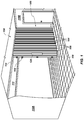
- FIG. 1 is a perspective view of an embodiment of a movable partition system of the present disclosure
- FIG. 2 is a simplified top view illustrating some components of the movable partition system of FIG. 1 ;
- FIG. 3 is a simplified top view similar to FIG. 2 illustrating an embodiment of a chain tensioner device of the movable partition system of FIG. 1 ;
- FIG. 4 is a top plan view showing in detail the chain tensioner device of FIG. 3 ;
- FIG. 5 is a perspective view showing certain components of the chain tensioner device of FIG. 4 ;
- FIG. 6 is a side view showing certain components of the chain tensioner device of FIG. 4 coupled to an embodiment of a track.
- the term “substantially” means to a degree that one skilled in the art would understand that the given parameter, property, or condition is met with a small degree of variance, such as within acceptable manufacturing tolerances.
- relational terms such as “first,” “second,” “vertical,” “horizontal,” etc., describe elements when viewed from the perspectives shown in the figures and do not connote or depend on any specific preference, orientation, or order, except where the context clearly indicates otherwise.
- the terms “longitudinal” and “longitudinally” refer to a direction at least substantially parallel to a length of the component.
- a member configured to slide “longitudinally” along a rod is configured to slide in a direction at least substantially parallel to a length of the rod.
- FIG. 1 illustrates an embodiment of a movable partition system 100 of the present disclosure.
- the movable partition system 100 may be an automatic movable partition system, in that the movable partition system 100 includes a movable partition 102 that may be automatically extended, automatically retracted, or both automatically extended and automatically retracted. In some embodiments, the movable partition 102 also may be manually extended and/or retracted if desired.
- the movable partition 102 may be used for partitioning space, as a sound bather, as a fire barrier, as a security barrier, for combinations of such purposes, or for other purposes.
- the space to be partitioned by the movable partition 102 may be defined at least partially by a first vertical surface 110 A (e.g., a wall), a second vertical surface 110 B, and a horizontal surface 112 (e.g., a ceiling, a floor, a header) extending between the first and second vertical surfaces 110 A and 110 B, respectively.
- a first vertical surface 110 A e.g., a wall
- a second vertical surface 110 B e.g., a horizontal surface 112 (e.g., a ceiling, a floor, a header) extending between the first and second vertical surfaces 110 A and 110 B, respectively.
- the movable partition 102 may comprise, for example, an accordion-type door, as shown in FIG. 1 .
- the movable partition 102 may be formed with a plurality of panels 104 that are connected to one another.
- the panels 104 may be connected together with hinges or other hinge-like members 106 .
- the panels 104 may be directly coupled to one another in such a manner as to allow the panels 104 to fold in a hinged manner.
- the hinged connection of the panels 104 enables the panels 104 to fold in an accordion manner and the movable partition 102 to collapse as the movable partition 102 is retracted, which may enable the movable partition 102 to be compactly stored in a pocket 108 formed in the second vertical surface 110 B of a structure, such as a building, when in a retracted or folded state.
- FIG. 1 While embodiments illustrated and described with respect to the drawings of the disclosure are directed to a single accordion folding movable partition 102 , other movable partitions may be used.
- a two-door, or bi-part door, system may be utilized wherein two similarly configured doors extend across a space and join together to form an appropriate barrier.
- the disclosure is applicable to movable partitions or barriers other than accordion folding doors, such as sliding doors, windows, and screens.
- Control of the movement of the movable partition 102 may be accomplished, in some embodiments, by the use of sensors, controls, and a drive mechanism.
- the movable partition 102 when used as a fire door, for example, may include a switch or actuator 126 , commonly referred to as “panic hardware.” Actuation of the panic hardware 126 enables a person located on one side of the movable partition 102 to cause the door to be opened if it is closed, or to stop movement while it is closing, enabling egress through the barrier formed by the door as needed. Controls may also be located in other locations (e.g., remotely) and may be configured to extend or retract the movable partition 102 manually or automatically, such as when a fire alarm activates, at a certain time or date, or when other conditions are met.
- the movable partition 102 may be coupled to (e.g., hang from) a track 114 mounted to a horizontal surface 112 along which the movable partition 102 moves as the movable partition 102 is expanded (i.e., closed) and retracted (i.e., opened). To deploy the movable partition 102 to an extended position, the movable partition 102 is moved along the track 114 .
- FIG. 2 illustrates a simplified top view of a movable partition system 100 .
- a leading end of the movable partition 102 shown as a lead post 116 , matingly (i.e., complementarily) engages with a jamb 119 or door post that may be formed in the first vertical surface 110 A of a structure (or on a leading end of another complementary partition), when the movable partition 102 is in a deployed or an extended state.
- the jamb 119 may be flat or a flat portion of the first vertical surface 110 A and the lead post 116 may be flat for abutting against the flat jamb 119 or flat portion of the first vertical surface 110 A.
- a movable partition 102 may include, by way of non-limiting example, a first sheet 105 A of panels 104 and a second sheet 105 B of panels 104 that is laterally spaced from the first sheet 105 A of the panels 104 .
- Such a configuration may be used as a fire door wherein the first sheet 105 A acts as a primary fire and smoke barrier, the space 122 between the first sheet 105 A and the second sheet 105 B acts as an insulator or a buffer zone, and the second sheet 105 B acts as a secondary fire and smoke barrier.
- Such a configuration may also be useful as an acoustical barrier when the movable partition 102 is used to subdivide a space into multiple rooms.
- the movable partition 102 may include a motor assembly 134 for driving the movable partition 102 across a space.
- the motor assembly 134 may include a motor (not shown) and a rotatable drive member 136 (e.g., a sprocket, a gear, a toothed wheel) configured to be driven by the motor.
- the motor may be carried by the movable partition 102 , such as within the space 122 between the first and second sheets 105 A and 105 B.
- the rotatable drive member 136 may be configured to be complementary to and engaged with a chain 130 (e.g., a roller chain) (see FIGS. 3 & 4 ).
- the motor assembly 134 may be coupled with the movable partition 102 in such a manner that rotation of the rotatable drive member 136 engaged with the chain 130 causes at least a portion of the movable partition 102 to move across the space.
- the motor assembly 134 may be rigidly attached to a leading end of the movable partition 102 , such as at or near the lead post 116 .
- FIG. 3 is a simplified top plan view similar to that of FIG. 2 illustrating an embodiment of certain components of the movable partition system 100 .
- the movable partition system 100 of the present disclosure may include a chain tensioner device 150 for tightening or loosening a chain 130 (e.g., a roller chain) or other elongated drive member (e.g., a belt, a toothed belt, etc.).
- the chain tensioner device 150 may include a first endplate 160 positioned at or near the first vertical surface 110 A and a second endplate 170 positioned at or near the second vertical surface 110 B.
- the second endplate 170 may be positioned within the pocket 108 formed in the second vertical surface 110 B.
- the chain 130 may be fixed at a first end 131 to the first endplate 160 of the chain tensioner device 150 and at a second end 132 to the second endplate 170 of the chain tensioner device 150 .
- FIG. 3 illustrates the second endplate 170 of the chain tensioner device 150 located in the pocket 108 of the second vertical surface 110 B
- the disclosure is not so limited.
- the chain tensioner device 150 may be installed in an opposite orientation.
- the first endplate 160 of the chain tensioner device 150 may be positioned at or near the second vertical surface 110 B and the second endplate 170 of the chain tensioner device 150 may be positioned at or near the first vertical surface 110 A.
- the chain 130 and the rotatable drive member 136 may have complementary features such that rotation of the rotatable drive member 136 forces the movable partition 102 (see FIG. 2 ) in a desired direction.
- the rotatable drive member 136 may be rotated and the leading edge of the movable partition 102 may proceed along the track 114 , thus driving the motor assembly 134 and, consequently, the movable partition 102 (or a portion thereof) across the space.
- the rotatable drive member 136 may be rotated in the opposite direction, forcing the movable partition 102 to proceed along the track 114 in the opposite direction.
- the movable partition 102 When the movable partition 102 is retracted, it may be stored at least partially in the pocket 108 in the second vertical surface 110 B.
- FIG. 4 illustrates an embodiment of a chain tensioner device 150 of the present disclosure.
- the chain tensioner device 150 may include a first endplate 160 including a first bracket 162 configured to secure the chain 130 to the first endplate 160 .
- the first bracket 162 may include a hole or a notch in which a first end 131 of the chain 130 or a chain connecting member (e.g., a so-called “master link”) may be at least partially disposed.
- the first endplate 160 may have at least one endplate guide block 163 coupled thereto to assist in installing and aligning the first endplate 160 with the track 114 , as will be described in more detail below.
- the first endplate 160 may optionally include one or more fasteners (not shown) for installing the first endplate 160 in a movable partition system 100 proximate (e.g., against) the first vertical surface 110 A (see FIG. 3 ).
- the one or more fasteners may include at least one of a screw, a bolt, a nail, a weld, and an adhesive.
- the first endplate 160 and its components may be formed of any suitably rigid material, such as at least one of metal, plastic, ceramic, wood, etc.
- the chain tensioner device 150 may also include a second endplate 170 .
- the second endplate 170 may include a second bracket 172 configured to secure the chain 130 to the second endplate 170 .
- the second bracket 172 may include a hole or a notch in which a second end 132 of the chain 130 or a chain connecting member may be disposed.
- the second endplate 170 may optionally include one or more fasteners (not shown) for installing the second endplate 170 in a movable partition system 100 proximate (e.g., against) the second vertical surface 110 B (see FIG. 3 ).
- the second endplate 170 may have at least one endplate guide block 163 coupled thereto to assist in installing and aligning the second endplate 170 with the track 114 , as will be described in more detail below.
- the second endplate 170 may also include an adjustment mechanism 180 for adjusting tension in the chain 130 .
- the adjustment mechanism 180 may be located on a first side 175 of the second endplate 170 facing the space to be partitioned by the movable partition 102 and opposite the second vertical surface 110 B.
- the adjustment mechanism 180 may include an elongated member 182 (e.g., a rod, a post, a threaded rod) and a carriage member 184 .
- the elongated member 182 of the adjustment mechanism 180 may be coupled to the first side 175 of the second endplate 170 .
- the elongated member 182 may extend from the surface of the second endplate 170 on the first side 175 thereof.
- the carriage member 184 may be mounted on and configured to slide longitudinally along the elongated member 182 .
- the carriage member 184 may be disposed at least partially around the elongated member 182 and capable of sliding along the elongated member 182 longitudinally.
- the adjustment mechanism 180 may optionally include a threaded nut 186 engaged with the elongated member 182 and configured to hold the carriage member 184 in place along the elongated member 182 and/or move the carriage member 184 longitudinally along the elongated member 182 .
- the second endplate 170 and its components may be formed of any suitably rigid material, such as at least one of metal, plastic, ceramic, wood, etc.
- the second bracket 172 may be coupled to the adjustment mechanism 180 .
- the second bracket 172 may be rigidly coupled to the carriage member 184 of the adjustment mechanism 180 with at least one of a weld, an adhesive, a screw, etc.
- the second bracket 172 and the carriage member 184 may be a single unit formed of a unitary body. In other words, the second bracket 172 and the carriage member 184 need not be formed separately and then coupled together. Rather, the present disclosure includes a unitary member that performs the functions of both the second bracket 172 and the carriage member 184 .
- the second bracket 172 may be separated from the first side 175 of the second endplate 170 by a distance 178 .
- a tension of the chain 130 coupled to the second bracket 172 may be adjusted by manipulating the adjustment mechanism 180 to adjust the distance 178 .
- the distance 178 may be adjusted by rotating the threaded nut 186 about the elongated member 182 . For example, tightening the threaded nut 186 moves it longitudinally along the elongated member 182 to slide the carriage member 184 of the adjustment mechanism 180 longitudinally along the elongated member 182 .
- the second bracket 172 coupled to the carriage member 184 may also move longitudinally in relation to the elongated member 182 and the distance 178 between the first side 175 of the second endplate 170 and the second bracket 172 may be decreased. Decreasing the distance 178 may cause more tension in the chain 130 compared to a starting distance 178 . Conversely, loosening the threaded nut 186 may enable the carriage member 184 to move longitudinally along the elongated member 182 in an opposite direction responsive to tension in the chain 130 , thereby increasing the distance 178 and decreasing the tension in the chain 130 . In this manner, tension in the chain 130 may be adjusted by manipulating the adjustment mechanism 180 .
- the second endplate 170 may have at least one endplate guide block 163 coupled thereto.
- the at least one endplate guide block 163 may be configured to be at least partially disposed within an internal cavity 120 of the track 114 .
- the internal cavity 120 may be a central channel (e.g., a so-called “chain guide”) of the track 114 , as shown in FIG. 6 .
- the at least one endplate guide block 163 coupled to the second endplate 170 may be configured to abut against at least one internal surface 115 of the track 114 .
- the at least one endplate guide block 163 may be configured to impede or eliminate movement of the second endplate 170 in up-and-down and/or left-and-right directions (when viewed in the perspective shown in FIG. 6 ) relative to the track 114 coupled thereto.
- the first endplate 160 may also have at least one endplate guide block 163 coupled thereto ( FIG. 4 ) that is configured to be disposed at least partially within the track 114 in a manner similar to that shown in FIG. 6 .
- a bracket guide block 173 may be coupled to the second bracket 172 and configured to impede or eliminate rotation of the second bracket 172 and the carriage member 184 about the elongated member 182 .
- the bracket guide block 173 may be configured to abut against the at least one internal surface 115 of the track 114 , such as within the internal cavity 120 of the track 114 .
- the bracket guide block 173 may help maintain alignment of the chain 130 along the track 114 .
- the bracket guide block 173 may counteract a force tending to rotate the carriage member 184 and the second bracket 172 about the elongated member 182 .
- bracket guide block 173 may help maintain the chain 130 in alignment with the track 114 by keeping the bracket 172 to which the chain 130 is coupled in approximately the same rotational position relative to the elongated member 182 .
- the position of the first end 131 ( FIG. 4 ) of the chain 130 may be fixed in an up-and-down direction (when viewed in the perspective of FIG. 6 ) relative to the track 114 by the bracket guide block 173 .
- the movable partition system 100 of the present disclosure may offer some advantages over prior known movable partition systems.
- a chain adjustment mechanism is located on a back side of an endplate opposite the space to be partitioned (e.g., a side of the endplate closest to a vertical surface to which the endplate is attached). Adjustment of the tension of a chain may require accessing the adjustment mechanism located on the back side of the endplate.
- the endplate may have to be removed to access the chain adjustment mechanism, there may be a small space behind the endplate that is difficult to access, or it may be necessary to access the adjustment mechanism from the back side of the vertical surface.
- the adjustment mechanism 180 of present disclosure may be located on the first side 175 of the second endplate 170 facing the space to be partitioned by the movable partition 102 , as described above (see FIGS. 3-6 ).
- the movable partition system 100 of the present disclosure may allow a user to avoid working in such a confined space, removing an endplate, or accessing a back side of the second vertical surface 110 B to gain access to the adjustment mechanism 180 to adjust tension in the chain 130 . Therefore, the movable partition system 100 of the present disclosure including the chain tensioner device 150 may reduce time, effort, and cost involved in installing and maintaining movable partition systems by providing easier access to the adjustment mechanism 180 as compared to prior known configurations.
- the present disclosure also includes methods of adjusting a tension in a chain 130 of a movable partition system 100 installed within a structure.
- an adjustment mechanism 180 located on a first side 175 of an endplate 170 may be manipulated to adjust tension in the chain 130 .
- the endplate 170 may be positioned proximate a vertical surface 110 B of the structure.
- the first side 175 of the endplate 170 may face a space to be partitioned with a movable partition 102 of the movable partition system 100 .
- the adjustment mechanism 180 may be manipulated by adjusting a distance 178 separating a bracket 172 attached to a second end 132 of the chain 130 and a surface of the endplate 170 on a first side 175 thereof.
- the distance 178 may be adjusted by, for example, turning a threaded nut 186 about an elongated member 182 coupled to the endplate 170 on the first side 175 thereof.
- a carriage member 184 may be coupled with the second bracket 172 and slidingly coupled to the elongated member 182 .
- the threaded nut 186 may be located proximate the carriage member 184 on the elongated member 182 .
- a washer may be disposed between the threaded nut 186 and the carriage member 184 .
- the threaded nut 186 When the threaded nut 186 is turned about the elongated member 182 , the threaded nut 186 may push against the carriage member 184 with greater or lesser force depending on the direction the threaded nut 186 is turned. This greater or lesser force may cause the second bracket 172 coupled to the carriage member 184 to move toward or away from the endplate 170 , thus adjusting the distance 178 between the second bracket 172 and the surface of the endplate 170 .
- Tension in the chain 130 may be adjusted responsive to the manipulation of the adjustment mechanism 180 .
- the first end 131 of the chain 130 may be attached (e.g., fixed) to another bracket 162 on another endplate 160 positioned proximate another vertical surface 110 A of the structure.
- the another bracket 162 may be on a side of the another endplate 160 facing the space to be partitioned with the movable partition 102 of the movable partition system 100 .
- the movement of the second end 132 of the chain 130 responsive to the manipulating the adjustment mechanism 180 may cause the tension in the chain 130 to be adjusted.
- the present disclosure also includes methods of installing a movable partition system 100 within a structure (e.g., a building).
- the method may include installing a movable partition system 100 in a space defined at least partially by two vertical surfaces 110 A and 110 B and at least one horizontal surface 112 extending between the two vertical surfaces 110 A and 110 B.
- the space in which the movable partition system 100 is installed may be between the two vertical surfaces 110 A and 110 B and the at least one horizontal surface 112 extending between the two vertical surfaces 110 A and 110 B.
- a track 114 may be mounted to the at least one horizontal surface 112 .
- a movable partition 102 may be coupled to the track 114 such that the movable partition 102 is capable of extending and/or retracting across the space.
- a chain tensioner device 150 may be installed within the structure.
- a first end 131 of a chain 130 may be attached to a first endplate 160 of the chain tensioner device 150 and a second end 132 of the chain 130 may be attached to a second endplate 170 of the chain tensioner device 150 .
- a tension in the chain 130 may be adjusted by manipulating an adjustment mechanism 180 of the chain tensioner device 150 .
- Installing the chain tensioner device 150 within the structure may include mounting a first endplate 160 to the structure proximate a first vertical surface 110 A.
- the first endplate 160 may include a first bracket 162 configured for attaching a chain 130 thereto.
- a second endplate 170 may be mounted to the structure proximate a second vertical surface 110 B.
- the second endplate 170 may include a second bracket 172 configured for attaching a chain 130 thereto located on a first side 175 of the second endplate 170 opposite the second vertical surface 110 B.
- the second bracket 172 and a surface of the second endplate 170 on the first side 175 thereof may be separated by a distance 178 .
- the second bracket 172 may be movable relative to the first side 175 of the second endplate 170 .
- the second endplate 170 may further include an adjustment mechanism 180 located on the first side 175 of the second endplate 170 .
- the adjustment mechanism 180 may be operably coupled with the second bracket 172 and configured for adjusting the distance 178 separating the second bracket 172 and the surface of the second endplate 170 on the first side 175 thereof.
- the adjustment mechanism 180 may include a carriage member 184 coupled with the second endplate 170 by an elongated member 182 .
- the adjustment mechanism 180 of the chain tensioner device 150 may be manipulated by adjusting the distance 178 separating the second bracket 172 and the surface of the second endplate 170 on a first side 175 thereof.
- the distance 178 may be adjusted by moving the carriage member 184 coupled with the second endplate 170 by the elongated member 182 longitudinally along the elongated member 182 .
- the manipulation of the adjustment mechanism 180 may be accomplished by rotating (e.g., tightening or loosening) a threaded nut 186 about the elongated member 182 .
- the threaded nut 186 may be tightened to push against the carriage member 184 , causing the carriage member 184 to slide along the elongated member 182 closer to the first side 175 of the second endplate 170 . Consequently, the second bracket 172 coupled to the carriage member 184 may also move closer to the first side 175 of the second endplate 170 , decreasing the distance 178 . Such movement may also cause the chain 130 to be extended, increasing the tension therein. Conversely, the threaded nut 186 may be loosened to relieve some pressure against the carriage member 184 .
- the tension in the chain 130 may pull the second bracket 172 and the carriage member 184 coupled thereto away from the first side 175 of the second endplate 170 , increasing the distance 178 and decreasing the tension in the chain 130 .
- Manipulating the adjustment mechanism 180 in this manner may, therefore, adjust the tension in the chain 130 .
- the present disclosure includes chain tensioner devices comprising a chain, a first endplate configured for attachment to a first end of the chain, and a second endplate having a bracket configured for attachment to an opposite second end of the chain.
- the bracket is located on a first side of the second endplate and separated a distance from a surface of the second endplate on the first side of the second endplate, and the bracket is movable relative to the first side of the second endplate.
- the second endplate also includes an adjustment mechanism located on the first side of the second endplate and operably coupled with the bracket. The adjustment mechanism is configured for adjusting the distance separating the bracket from the surface of the second endplate on the first side thereof.
- the present disclosure includes movable partition systems that include such chain tensioner devices.
- the movable partition systems may be configured for installation within a structure, such as a building, in a space defined between two vertical surfaces (e.g., walls) and at least one horizontal surface (e.g., a ceiling and/or a floor) extending between the two vertical surfaces.
- the movable partition systems may comprise a track configured to be mounted to the at least one horizontal surface, a movable partition configured to be coupled to the track and to extend and retract across the space along the track, a chain configured to extend along the track, and a chain tensioner device as described herein.
- the chain tensioner device may be used to selectively adjust a tension in the chain when the chain is installed for use.
- the chain tensioner device may include a first endplate having a first bracket configured for attachment to a first end of the chain, and a second endplate having a second bracket configured for attachment to an opposite, second end of the chain.
- the second bracket is located on a first side of the second endplate configured to face the space and separated a distance from a surface of the second endplate on the first side of the second endplate, and the second bracket is movable relative to the first side of the second endplate.
- the second endplate also includes an adjustment mechanism located on the first side of the second endplate and operably coupled with the second bracket. The adjustment mechanism is configured for adjusting the distance separating the second bracket from the surface of the second endplate on the first side thereof.
- the movable partition systems may further include a motor for driving movement of at least a portion of the movable partition along the track using the chain to cause extension and retraction of the movable partition.
- the present disclosure includes methods of using chain tensioner devices as described herein.
- tension in a chain of a movable partition system installed within a structure may be adjusted by manipulating an adjustment mechanism located on a first side of an endplate positioned proximate a vertical surface of the structure and facing a space to be partitioned by a movable partition of the movable partition system.
- Manipulating the adjustment mechanism may include adjusting a distance separating a bracket attached to an end of the chain and a surface of the endplate on the first side thereof.
- Another end of the chain may be attached to another bracket on another endplate facing the space to be partitioned and positioned proximate another vertical surface, such that the tension in the chain is adjusted responsive to the manipulation of the adjustment mechanism.
- the present disclosure includes methods of installing a movable partition system including a chain tensioner device as described herein within a building or other structure.
- a track may be mounted to at least one horizontal surface in the building.
- a movable partition may be coupled to the track such that the movable partition is capable of extending and retracting across a space within the building along the track.
- a chain tensioner device may be installed within the building. Installation of the chain tensioner device may be carried out by mounting a first endplate to the building proximate a first vertical surface of the building (e.g., a wall of the building), and mounting a second endplate to the building proximate a second vertical surface of the building (e.g., another wall of the building).
- the first endplate may comprise a first bracket.
- the second endplate may comprise a second bracket located on a first side of the second endplate opposite the second vertical surface and separated a distance from a surface of the second endplate on the first side of the second endplate.
- the second bracket may be movable relative to the first side of the second endplate.
- the second endplate may further comprise an adjustment mechanism located on the first side of the second endplate and operably coupled with the second bracket.
- the adjustment mechanism may be configured for adjusting the distance separating the second bracket from the surface of the second endplate on the first side thereof.
- a first end of a chain may be attached to the first bracket of the first endplate, and a second end of the chain may be attached to the second bracket of the second endplate.
- a tension in the chain then may be adjusted by manipulating the adjustment mechanism and adjusting the distance separating the second bracket from the surface of the second endplate on the first side thereof.
Landscapes
- Engineering & Computer Science (AREA)
- Mechanical Engineering (AREA)
- Power-Operated Mechanisms For Wings (AREA)
Abstract
Description
Claims (20)
Priority Applications (1)
| Application Number | Priority Date | Filing Date | Title |
|---|---|---|---|
| US15/676,538 US10697219B2 (en) | 2011-10-18 | 2017-08-14 | Tensioners for movable partition systems, movable partition systems including such tensioners, and related methods |
Applications Claiming Priority (2)
| Application Number | Priority Date | Filing Date | Title |
|---|---|---|---|
| US13/275,541 US9732546B2 (en) | 2011-10-18 | 2011-10-18 | Chain tensioners for movable partition systems, movable partition systems including such chain tensioners, and related methods |
| US15/676,538 US10697219B2 (en) | 2011-10-18 | 2017-08-14 | Tensioners for movable partition systems, movable partition systems including such tensioners, and related methods |
Related Parent Applications (1)
| Application Number | Title | Priority Date | Filing Date |
|---|---|---|---|
| US13/275,541 Continuation US9732546B2 (en) | 2011-10-18 | 2011-10-18 | Chain tensioners for movable partition systems, movable partition systems including such chain tensioners, and related methods |
Publications (2)
| Publication Number | Publication Date |
|---|---|
| US20170342754A1 US20170342754A1 (en) | 2017-11-30 |
| US10697219B2 true US10697219B2 (en) | 2020-06-30 |
Family
ID=48085008
Family Applications (2)
| Application Number | Title | Priority Date | Filing Date |
|---|---|---|---|
| US13/275,541 Expired - Fee Related US9732546B2 (en) | 2011-10-18 | 2011-10-18 | Chain tensioners for movable partition systems, movable partition systems including such chain tensioners, and related methods |
| US15/676,538 Active 2032-05-02 US10697219B2 (en) | 2011-10-18 | 2017-08-14 | Tensioners for movable partition systems, movable partition systems including such tensioners, and related methods |
Family Applications Before (1)
| Application Number | Title | Priority Date | Filing Date |
|---|---|---|---|
| US13/275,541 Expired - Fee Related US9732546B2 (en) | 2011-10-18 | 2011-10-18 | Chain tensioners for movable partition systems, movable partition systems including such chain tensioners, and related methods |
Country Status (1)
| Country | Link |
|---|---|
| US (2) | US9732546B2 (en) |
Families Citing this family (3)
| Publication number | Priority date | Publication date | Assignee | Title |
|---|---|---|---|---|
| US20130162420A1 (en) * | 2010-04-09 | 2013-06-27 | James Marshall Stoddard | Combination Tie Strap Tensioning Assembly with Tension Monitor |
| CN106931109A (en) * | 2016-12-14 | 2017-07-07 | 维德(肇庆)重型机器有限公司 | A kind of drive sprocket strainer run along cyclic track |
| DE102017109612A1 (en) * | 2017-05-04 | 2018-11-08 | Burkhard Schmitz | partition wall |
Citations (40)
| Publication number | Priority date | Publication date | Assignee | Title |
|---|---|---|---|---|
| US721946A (en) | 1902-06-02 | 1903-03-03 | Julian A Foster | Wire-stretcher. |
| US4009765A (en) | 1975-05-07 | 1977-03-01 | Towmotor Corporation | Adjustable lift chain anchor for fork lift mast units |
| US4105221A (en) | 1977-02-04 | 1978-08-08 | Fleming Ancel H | Tensioning linkage |
| US4312426A (en) | 1977-03-10 | 1982-01-26 | Towmotor Corporation | Chain anchoring arrangement |
| US4567627A (en) | 1983-08-16 | 1986-02-04 | W. W. Patterson Company | Load binder apparatus |
| US4617703A (en) | 1984-10-11 | 1986-10-21 | Schaeffer Richard J | Device for tightening chains and the like |
| US4834161A (en) | 1986-02-11 | 1989-05-30 | Won-Door Corporation | Folding firedoor lead post assembly |
| US4924929A (en) | 1986-02-11 | 1990-05-15 | Won-Door Corporation | Folding firedoor lead post assembly |
| US5297782A (en) * | 1991-10-10 | 1994-03-29 | The Chamberlain Group, Inc. | Modular snubber apparatus |
| US5638639A (en) | 1994-04-28 | 1997-06-17 | Won-Door Corporation | Emergency door with retractable nose piece, interiorly mounted operating hardware, and hinge supports |
| US6662848B2 (en) | 2002-02-20 | 2003-12-16 | Won-Door Corporation | Automatic door and method of operating same |
| US7050283B2 (en) | 2002-04-29 | 2006-05-23 | Won-Door Corporation | Method and apparatus for protecting monitor circuit from fault condition |
| US7190132B2 (en) | 2004-12-09 | 2007-03-13 | Won-Door Corporation | Method and apparatus for motor control using relays |
| US7220198B2 (en) * | 2002-10-08 | 2007-05-22 | Smc Kabushiki Kaisha | Electric actuator |
| US20080115896A1 (en) | 2006-11-03 | 2008-05-22 | Won-Door Corporation | Movable partitions with lateral restraint devices and related methods |
| US7478663B2 (en) | 2004-04-02 | 2009-01-20 | Won-Door Corporation | Method, apparatus and system for directionally controlling a movable partition |
| US7656129B2 (en) | 2007-01-30 | 2010-02-02 | Won-Door Corporation | Method and apparatus for battery-backed power supply and battery charging |
| US20100056311A1 (en) | 2008-09-03 | 2010-03-04 | Cornell Iron Works, Inc. | Self Adjusting Track Chain Adjustment Trolley |
| US20100102764A1 (en) | 2008-10-23 | 2010-04-29 | Won-Door Corporation | Methods, systems, and devices for a motor control system |
| US7737860B2 (en) | 2007-10-12 | 2010-06-15 | Won-Door Corporation | Systems and methods for monitoring automatic doors |
| US7740046B2 (en) | 2007-04-27 | 2010-06-22 | Won-Door Corporation | Method, apparatus and system for controlling a movable partition |
| US20100214709A1 (en) | 2009-02-20 | 2010-08-26 | Won-Door Corporation | Methods and systems relating to overcurrent circuit protection |
| US20100299889A1 (en) | 2009-06-02 | 2010-12-02 | Won-Door Corporation | Movable partitions, header assemblies for movable partitions, and related methods |
| US7845384B2 (en) | 2007-08-16 | 2010-12-07 | Won-Door Corporation | Partition systems and methods of operating partition systems |
| US7845386B2 (en) | 2006-11-03 | 2010-12-07 | Won-Door Corporation | Movable partitions, components for movable partitions and related methods |
| US7854248B2 (en) | 2007-03-29 | 2010-12-21 | Won-Door Corporation | Vision panel for movable partition, movable partitions and related methods |
| US20110000625A1 (en) | 2009-07-02 | 2011-01-06 | Won-Door Corporation | Movable partitions, leading end assemblies for movable partitions and related methods |
| US20110005689A1 (en) | 2009-07-10 | 2011-01-13 | Won-Door Corporation | Motor control systems, foldable partitions employing motor control systems, methods of monitoring the operation of electric motors and foldable partitions |
| US7874341B2 (en) | 2006-06-21 | 2011-01-25 | Won-Door Corporation | Hinged connection, movable partitions using same and related methods |
| US20110024061A1 (en) | 2009-07-28 | 2011-02-03 | Won-Door Corporation | Movable partitions, header assemblies for movable partitions, and methods of forming header assemblies for movable partitions |
| US7886804B2 (en) | 2008-01-30 | 2011-02-15 | Won-Door Corporation | Folding partitions, components therefor and related methods |
| US20110036513A1 (en) | 2007-01-30 | 2011-02-17 | Won-Door Corporation | Method and apparatus for battery-backed power supply and battery charging |
| US20110036016A1 (en) | 2009-08-17 | 2011-02-17 | Won-Door Corporation | Methods, apparatuses, and systems for driving a movable partition |
| US20110036509A1 (en) | 2009-08-17 | 2011-02-17 | Won-Door Corporation | Movable partition systems including intumescent material and methods of controlling and directing intumescent material around the perimeter of a movable partition system |
| US7926538B2 (en) | 2007-01-11 | 2011-04-19 | Won-Door Corporation | Lateral restraint for a movable partition, movable partitions incorporating same and related methods |
| US20110088322A1 (en) | 2009-10-21 | 2011-04-21 | Won-Door Corporation | Closure assemblies for fire doors, fire doors including such closure assemblies and methods of locking fire doors |
| US7931067B2 (en) | 2006-11-03 | 2011-04-26 | Won-Door Corporation | Movable partitions with lateral restraint devices and related methods |
| US20110203746A1 (en) | 2010-02-25 | 2011-08-25 | Won-Door Corporation | Folding partitions having adjoining panels and related methods |
| US20110247275A1 (en) | 2010-04-12 | 2011-10-13 | Won-Door Corporation | Methods, apparatuses, and systems for movable partitions |
| US20110247764A1 (en) | 2010-04-12 | 2011-10-13 | Won-Door Corporation | Movable partition systems and components thereof including chain guide structures, and methods of forming and installing same |
-
2011
- 2011-10-18 US US13/275,541 patent/US9732546B2/en not_active Expired - Fee Related
-
2017
- 2017-08-14 US US15/676,538 patent/US10697219B2/en active Active
Patent Citations (47)
| Publication number | Priority date | Publication date | Assignee | Title |
|---|---|---|---|---|
| US721946A (en) | 1902-06-02 | 1903-03-03 | Julian A Foster | Wire-stretcher. |
| US4009765A (en) | 1975-05-07 | 1977-03-01 | Towmotor Corporation | Adjustable lift chain anchor for fork lift mast units |
| US4105221A (en) | 1977-02-04 | 1978-08-08 | Fleming Ancel H | Tensioning linkage |
| US4312426A (en) | 1977-03-10 | 1982-01-26 | Towmotor Corporation | Chain anchoring arrangement |
| US4567627A (en) | 1983-08-16 | 1986-02-04 | W. W. Patterson Company | Load binder apparatus |
| US4617703A (en) | 1984-10-11 | 1986-10-21 | Schaeffer Richard J | Device for tightening chains and the like |
| US4834161A (en) | 1986-02-11 | 1989-05-30 | Won-Door Corporation | Folding firedoor lead post assembly |
| US4924929A (en) | 1986-02-11 | 1990-05-15 | Won-Door Corporation | Folding firedoor lead post assembly |
| US5297782A (en) * | 1991-10-10 | 1994-03-29 | The Chamberlain Group, Inc. | Modular snubber apparatus |
| US5638639A (en) | 1994-04-28 | 1997-06-17 | Won-Door Corporation | Emergency door with retractable nose piece, interiorly mounted operating hardware, and hinge supports |
| US6662848B2 (en) | 2002-02-20 | 2003-12-16 | Won-Door Corporation | Automatic door and method of operating same |
| US7066297B2 (en) | 2002-02-20 | 2006-06-27 | Won-Door Corporation | Automatic door and method of operating same |
| US7050283B2 (en) | 2002-04-29 | 2006-05-23 | Won-Door Corporation | Method and apparatus for protecting monitor circuit from fault condition |
| US7220198B2 (en) * | 2002-10-08 | 2007-05-22 | Smc Kabushiki Kaisha | Electric actuator |
| US7845385B2 (en) | 2004-04-02 | 2010-12-07 | Won-Door Corporation | Steerable trollies for movable partitions, partition systems including steerable trolleys, and methods of closing partitions |
| US7478663B2 (en) | 2004-04-02 | 2009-01-20 | Won-Door Corporation | Method, apparatus and system for directionally controlling a movable partition |
| US7513293B2 (en) | 2004-04-02 | 2009-04-07 | Won-Door Corporation | Method and apparatus for directionally controlling a movable partition |
| US7190132B2 (en) | 2004-12-09 | 2007-03-13 | Won-Door Corporation | Method and apparatus for motor control using relays |
| US7874341B2 (en) | 2006-06-21 | 2011-01-25 | Won-Door Corporation | Hinged connection, movable partitions using same and related methods |
| US7931067B2 (en) | 2006-11-03 | 2011-04-26 | Won-Door Corporation | Movable partitions with lateral restraint devices and related methods |
| US7845386B2 (en) | 2006-11-03 | 2010-12-07 | Won-Door Corporation | Movable partitions, components for movable partitions and related methods |
| US20080115896A1 (en) | 2006-11-03 | 2008-05-22 | Won-Door Corporation | Movable partitions with lateral restraint devices and related methods |
| US7926538B2 (en) | 2007-01-11 | 2011-04-19 | Won-Door Corporation | Lateral restraint for a movable partition, movable partitions incorporating same and related methods |
| US20110186249A1 (en) | 2007-01-11 | 2011-08-04 | Won-Door Corporation | Methods of displacing movable partitions including a lateral restraint |
| US7782019B2 (en) | 2007-01-30 | 2010-08-24 | Won-Door Corporation | Method and apparatus for battery-backed power supply and battery charging |
| US20110036513A1 (en) | 2007-01-30 | 2011-02-17 | Won-Door Corporation | Method and apparatus for battery-backed power supply and battery charging |
| US7656129B2 (en) | 2007-01-30 | 2010-02-02 | Won-Door Corporation | Method and apparatus for battery-backed power supply and battery charging |
| US7854248B2 (en) | 2007-03-29 | 2010-12-21 | Won-Door Corporation | Vision panel for movable partition, movable partitions and related methods |
| US20110061820A1 (en) | 2007-03-29 | 2011-03-17 | Won-Door Corporation | Vision panel for movable partition, movable partition system and related method |
| US7740046B2 (en) | 2007-04-27 | 2010-06-22 | Won-Door Corporation | Method, apparatus and system for controlling a movable partition |
| US20110093095A1 (en) | 2007-04-27 | 2011-04-21 | Won-Door Corporation | Method, apparatus and system for controlling a movable partition |
| US7845384B2 (en) | 2007-08-16 | 2010-12-07 | Won-Door Corporation | Partition systems and methods of operating partition systems |
| US7737860B2 (en) | 2007-10-12 | 2010-06-15 | Won-Door Corporation | Systems and methods for monitoring automatic doors |
| US7886804B2 (en) | 2008-01-30 | 2011-02-15 | Won-Door Corporation | Folding partitions, components therefor and related methods |
| US20100056311A1 (en) | 2008-09-03 | 2010-03-04 | Cornell Iron Works, Inc. | Self Adjusting Track Chain Adjustment Trolley |
| US20100102764A1 (en) | 2008-10-23 | 2010-04-29 | Won-Door Corporation | Methods, systems, and devices for a motor control system |
| US20100214709A1 (en) | 2009-02-20 | 2010-08-26 | Won-Door Corporation | Methods and systems relating to overcurrent circuit protection |
| US20100299889A1 (en) | 2009-06-02 | 2010-12-02 | Won-Door Corporation | Movable partitions, header assemblies for movable partitions, and related methods |
| US20110000625A1 (en) | 2009-07-02 | 2011-01-06 | Won-Door Corporation | Movable partitions, leading end assemblies for movable partitions and related methods |
| US20110005689A1 (en) | 2009-07-10 | 2011-01-13 | Won-Door Corporation | Motor control systems, foldable partitions employing motor control systems, methods of monitoring the operation of electric motors and foldable partitions |
| US20110024061A1 (en) | 2009-07-28 | 2011-02-03 | Won-Door Corporation | Movable partitions, header assemblies for movable partitions, and methods of forming header assemblies for movable partitions |
| US20110036016A1 (en) | 2009-08-17 | 2011-02-17 | Won-Door Corporation | Methods, apparatuses, and systems for driving a movable partition |
| US20110036509A1 (en) | 2009-08-17 | 2011-02-17 | Won-Door Corporation | Movable partition systems including intumescent material and methods of controlling and directing intumescent material around the perimeter of a movable partition system |
| US20110088322A1 (en) | 2009-10-21 | 2011-04-21 | Won-Door Corporation | Closure assemblies for fire doors, fire doors including such closure assemblies and methods of locking fire doors |
| US20110203746A1 (en) | 2010-02-25 | 2011-08-25 | Won-Door Corporation | Folding partitions having adjoining panels and related methods |
| US20110247275A1 (en) | 2010-04-12 | 2011-10-13 | Won-Door Corporation | Methods, apparatuses, and systems for movable partitions |
| US20110247764A1 (en) | 2010-04-12 | 2011-10-13 | Won-Door Corporation | Movable partition systems and components thereof including chain guide structures, and methods of forming and installing same |
Also Published As
| Publication number | Publication date |
|---|---|
| US20170342754A1 (en) | 2017-11-30 |
| US20130091775A1 (en) | 2013-04-18 |
| US9732546B2 (en) | 2017-08-15 |
Similar Documents
| Publication | Publication Date | Title |
|---|---|---|
| US7931067B2 (en) | Movable partitions with lateral restraint devices and related methods | |
| US8365796B2 (en) | Methods, apparatuses, and systems for movable partitions | |
| CA2706112C (en) | Movable partitions with lateral restraint devices and related methods | |
| EP2273054B1 (en) | Extendable partition wall | |
| US9127453B2 (en) | Drive modules for movable partition systems and components thereof and related methods of installing drive modules | |
| US8316914B2 (en) | Movable partitions, header assemblies for movable partitions, and methods of forming header assemblies for movable partitions | |
| AU2010201467B2 (en) | Improvements Relating to Multi-fold Panel Assemblies | |
| US20080169069A1 (en) | Lateral restraint for a moveable partition, moveable partitions incorporating same and related methods | |
| US9074420B2 (en) | Methods, apparatuses, and systems for resisting lateral displacement of movable partitions | |
| KR101874013B1 (en) | Folding Door System | |
| US10697219B2 (en) | Tensioners for movable partition systems, movable partition systems including such tensioners, and related methods | |
| US20190119964A1 (en) | Latch mechanism for folding door or windows | |
| US9752332B2 (en) | Molding members for movable partition systems and header structures and components thereof, and related methods of installation | |
| US20130081333A1 (en) | Strikers, movable partition systems including such strikers, and related methods | |
| NZ579072A (en) | multi-fold panel assemblies with skewed support track, and frame structure to fully frame panels and for setting into a buidling opening |
Legal Events
| Date | Code | Title | Description |
|---|---|---|---|
| STPP | Information on status: patent application and granting procedure in general |
Free format text: DOCKETED NEW CASE - READY FOR EXAMINATION |
|
| STPP | Information on status: patent application and granting procedure in general |
Free format text: NON FINAL ACTION MAILED |
|
| STPP | Information on status: patent application and granting procedure in general |
Free format text: RESPONSE TO NON-FINAL OFFICE ACTION ENTERED AND FORWARDED TO EXAMINER |
|
| STPP | Information on status: patent application and granting procedure in general |
Free format text: AWAITING TC RESP., ISSUE FEE NOT PAID |
|
| STPP | Information on status: patent application and granting procedure in general |
Free format text: PUBLICATIONS -- ISSUE FEE PAYMENT RECEIVED |
|
| STCF | Information on status: patent grant |
Free format text: PATENTED CASE |
|
| CC | Certificate of correction | ||
| AS | Assignment |
Owner name: WON-DOOR CORPORATION, UTAH Free format text: ASSIGNMENT OF ASSIGNORS INTEREST;ASSIGNORS:SACCOMANNO, PAUL;COLEMAN, WILLIAM MICHAEL;REEL/FRAME:055219/0172 Effective date: 20111017 |
|
| FEPP | Fee payment procedure |
Free format text: ENTITY STATUS SET TO UNDISCOUNTED (ORIGINAL EVENT CODE: BIG.); ENTITY STATUS OF PATENT OWNER: LARGE ENTITY |
|
| MAFP | Maintenance fee payment |
Free format text: PAYMENT OF MAINTENANCE FEE, 4TH YEAR, LARGE ENTITY (ORIGINAL EVENT CODE: M1551); ENTITY STATUS OF PATENT OWNER: LARGE ENTITY Year of fee payment: 4 |