US1069686A - Spring-wheel. - Google Patents
Spring-wheel. Download PDFInfo
- Publication number
- US1069686A US1069686A US71594712A US1912715947A US1069686A US 1069686 A US1069686 A US 1069686A US 71594712 A US71594712 A US 71594712A US 1912715947 A US1912715947 A US 1912715947A US 1069686 A US1069686 A US 1069686A
- Authority
- US
- United States
- Prior art keywords
- shoes
- wheel
- spring
- felly
- rim
- Prior art date
- Legal status (The legal status is an assumption and is not a legal conclusion. Google has not performed a legal analysis and makes no representation as to the accuracy of the status listed.)
- Expired - Lifetime
Links
Images
Classifications
-
- B—PERFORMING OPERATIONS; TRANSPORTING
- B60—VEHICLES IN GENERAL
- B60B—VEHICLE WHEELS; CASTORS; AXLES FOR WHEELS OR CASTORS; INCREASING WHEEL ADHESION
- B60B9/00—Wheels of high resiliency, e.g. with conical interacting pressure-surfaces
- B60B9/02—Wheels of high resiliency, e.g. with conical interacting pressure-surfaces using springs resiliently mounted bicycle rims
Definitions
- Patented Au Q12, 1913 Patented Au Q12, 1913.
- Our invention relates to an improvement 'in spring wheels for vehicles.
- the invention consists in certain novel features of construction and combinations of parts which will he hereina-fmr fully de scribed and pointed out in the claims.
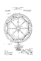
- Figure 1 is a View in side elevation with one of the side plates or sides of the casing removed to disclose the interior construction;
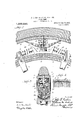
- Fig. 2 is an enlarged transverse sectional view;
- Fig. 3 is an enlarged vertical sectional view; and
- Figs. 4 and 5 are details.
- A represents the hub of a wheel, having spokes 1, 1, mounted therein, and carried by the spokes is a felly 2.
- the spokes project through and extend above the felly and are provided with buifers 3, 3, on each side thereof.
- a casing 4, open at the upper end, is provided with grooves 5 along the inner surface of each side for the reception of the rim 6, which is received in the casing, and is provided with lugs 7 which are received in the grooves 5 of the casing; the sides of the casing extending along the sides of the felly 2.
- Formed on the upper surface of the telly 2 and intermediate of the ends of the spokes 1 are concave grooves or recesses 8.
- Shoes 9 are mounted on the felly, and the lower portion of each shoe is provided with a projection 10 having a curved lower'surface which is received in the grooves 8', to permit of the shoe having a rocking action upon the felly and preventing the shoe from having any lateral movement.
- Pins 11, 11, are connected to the lower surface of the riln6, and adapted to extend into recesses- 12 formed in the upper surface of the shoes 9.
- Each pin 11 has a spiral spring 13 sur rounding it, and located below each spring and upon each shoe 9 is a semi-elliptical spring 14, the upperied es of which engage the lower or inner surlace of the rim 6.
- Bufiers 15 are formed at each end of theshoes 9, and received betweeneach end of the shoes and each side of the spokes and encircling the f nor; vs or nasirvicns:unnnssssnv seams- HEEL SpecificationjofiI etters- Ifatent; pp non fiied'au aistie 1' 2 and; THOMAS M. riivnnnwsigcitizens of the United;
- the tongue or projection 10 of the shoes causes the shoes to move in one direction-that is, they are capable of a rocking action, but are prevented from any lateral movement in the grooves 8 of the telly. The movement of the shoes on the telly is guided by the tongues 10 until the tension of the coil 0 tongues 10.
- shoes mounted on the folly having tongues which are adapted to he received in the grooves for holding allowing the shoes to have anoscillatory movement up'onthe telly, springs interposed '1' s ing, to".
- the ss 11 a These elements form the means for carryand felly and projecting beyond the telly, of a rim, shoes. movably mounted upon the 2. In a s ring wheel, the combination with a felly an a mm, the folly having grooves the shoes against lateral movement, but
Landscapes
- Engineering & Computer Science (AREA)
- Mechanical Engineering (AREA)
- Footwear And Its Accessory, Manufacturing Method And Apparatuses (AREA)
Description
J. E.-FISHER & T. M. ANDREWS.
SPRING= WHEEL. APPLIGATION FILED AUG,19, 1912'.
Patented Au Q12, 1913.
2 SHBETSSHEET 1'.
J. E. FISHER & T. M. ANDREWS. SPRING WHEEL. APPLIGATIOLI FILED AUG.19, 1912.
1,069,686, Patented Aug. 12, 1913;
I '2 SHEETS-SHEET 2.
r 4' llllllllllllIlllllillllllllllllllll "In" imme/am alum ree hv clsoeaendrS te of T nne se To a7] whom it may concern: Be it known that we iloiiiz 1? States, residing at Nashville, in the county invented certain new andiisefiil I'm ments in Spring-Wheels, of whichill; lowing is a specification.
Our invention relates to an improvement 'in spring wheels for vehicles.
The invention consists in certain novel features of construction and combinations of parts which will he hereina-fmr fully de scribed and pointed out in the claims.
In the accompanying drawings, Figure 1 is a View in side elevation with one of the side plates or sides of the casing removed to disclose the interior construction; Fig. 2 is an enlarged transverse sectional view; Fig. 3 is an enlarged vertical sectional view; and Figs. 4 and 5 are details.
A, represents the hub of a wheel, having spokes 1, 1, mounted therein, and carried by the spokes is a felly 2. The spokes project through and extend above the felly and are provided with buifers 3, 3, on each side thereof. A casing 4, open at the upper end, is provided with grooves 5 along the inner surface of each side for the reception of the rim 6, which is received in the casing, and is provided with lugs 7 which are received in the grooves 5 of the casing; the sides of the casing extending along the sides of the felly 2. Formed on the upper surface of the telly 2 and intermediate of the ends of the spokes 1 are concave grooves or recesses 8. Shoes 9 are mounted on the felly, and the lower portion of each shoe is provided with a projection 10 having a curved lower'surface which is received in the grooves 8', to permit of the shoe having a rocking action upon the felly and preventing the shoe from having any lateral movement. Pins 11, 11, are connected to the lower surface of the riln6, and adapted to extend into recesses- 12 formed in the upper surface of the shoes 9. Each pin 11 has a spiral spring 13 sur rounding it, and located below each spring and upon each shoe 9 is a semi-elliptical spring 14, the upperied es of which engage the lower or inner surlace of the rim 6. Bufiers 15 are formed at each end of theshoes 9, and received betweeneach end of the shoes and each side of the spokes and encircling the f nor; vs or nasirvicns:unnnssssnv seams- HEEL SpecificationjofiI etters- Ifatent; pp non fiied'au aistie 1' 2 and; THOMAS M. riivnnnwsigcitizens of the United;
dish rcex end -.hr i el '.-t e i springs t fi or semiellipti'cal" springs '14," and into the ecesses in the shoes 9, allowing the springs riio ve freely uponshapin and'the slioes ojgnove longitudinally of the folly. The tongue or projection 10 of the shoes causes the shoes to move in one direction-that is, they are capable of a rocking action, but are prevented from any lateral movement in the grooves 8 of the telly. The movement of the shoes on the telly is guided by the tongues 10 until the tension of the coil 0 tongues 10. until the tension of the coil springs 13 and semi-elliptical springs 14 is great enough to move the load, or until the buffers 3 and 15 of the spokes and shoes respectively come together, causing the wheel to become rigid from pressure in one direction, which causes the wheel to turn, after which the springs begin to equalize their pressure, thus making the wheel resilient, because the coil springs 13 and the flat. or elliptical springs 14: tend to hold the telly away from the inner periphery of the rim 6.
ing the entire load placed upon the axle, and when the Wheel is in -rnotion the springs and bufiers continually fall back or adjust the telly to such a position as to create a condition of continuous fall and recovery while the wheel is moving.
Having fully described our invention, what we claim as new and desire to secure by Letters Patent, is
1. In a spring wheel, the combination with a hub and felly, spokes connected to the hub felly and capable of an oscillating movement thereon, flexible means connecting the shoes to the rim for supporting the rim, ahd';resilient means interposed between the shoes and ends of spokes for limiting the movement of the shoes.
formed therein at intervals, shoes mounted on the folly having tongues which are adapted to he received in the grooves for holding allowing the shoes to have anoscillatory movement up'onthe telly, springs interposed '1' s ing, to". The ss 11 a These elements form the means for carryand felly and projecting beyond the telly, of a rim, shoes. movably mounted upon the 2. In a s ring wheel, the combination with a felly an a mm, the folly having grooves the shoes against lateral movement, but
the rim, and means conneetingthe shoes to resilient means located between the projeeting ends of the spokes and shoes for limiting -thm0vement0f the shoes.
' In testimony whereof we aflix our sign'a- 15 tures in the presence of two witnesses.
JOHN E. FISHER. THOMAS M. ANDREW'S.
between the shoes and rim for supporting the rim for holding theishoes in'placer j 3. In a; spring wheel, the combination with a hub and felly, spokes connected to the hub and 'felly and projecting beyond thefelly, of a rim, shoes movably mounted upon the felly, springs interposed between the shoes and rim and loosely mounted u on the shoes, means connectingthe shoes an rim together and fastening the springs to the shoes, and
Witnesses:
JOHN OHARn, J. C. T. MCCALL.
five cents each, by addressing the, Commissioner of Patents. Washington, D. G.
Copies 0; this patent may be obtained for
Priority Applications (1)
| Application Number | Priority Date | Filing Date | Title |
|---|---|---|---|
| US71594712A US1069686A (en) | 1912-08-19 | 1912-08-19 | Spring-wheel. |
Applications Claiming Priority (1)
| Application Number | Priority Date | Filing Date | Title |
|---|---|---|---|
| US71594712A US1069686A (en) | 1912-08-19 | 1912-08-19 | Spring-wheel. |
Publications (1)
| Publication Number | Publication Date |
|---|---|
| US1069686A true US1069686A (en) | 1913-08-12 |
Family
ID=3137923
Family Applications (1)
| Application Number | Title | Priority Date | Filing Date |
|---|---|---|---|
| US71594712A Expired - Lifetime US1069686A (en) | 1912-08-19 | 1912-08-19 | Spring-wheel. |
Country Status (1)
| Country | Link |
|---|---|
| US (1) | US1069686A (en) |
-
1912
- 1912-08-19 US US71594712A patent/US1069686A/en not_active Expired - Lifetime
Similar Documents
| Publication | Publication Date | Title |
|---|---|---|
| US1069686A (en) | Spring-wheel. | |
| US1066267A (en) | Vehicle-wheel. | |
| US1252736A (en) | Resilient wheel. | |
| US1156311A (en) | Spring-tire. | |
| US603710A (en) | Half to james aiken | |
| US1159961A (en) | Resilient wheel. | |
| US1061458A (en) | Vehicle-wheel. | |
| US1257220A (en) | Resilient wheel. | |
| US1067949A (en) | Resilient tire. | |
| US1132462A (en) | Vehicle-wheel. | |
| US1232991A (en) | Spring-wheel. | |
| US569370A (en) | Island | |
| US565795A (en) | Skate-wheel | |
| US996839A (en) | Resilient tire. | |
| US562224A (en) | Vehicle-wheel | |
| US975378A (en) | Vehicle-wheel. | |
| US1241235A (en) | Resilient wheel. | |
| US607057A (en) | labatt | |
| US1018774A (en) | Vehicle-wheel. | |
| US466776A (en) | Vehicle-wheel | |
| US1179235A (en) | Spring-wheel. | |
| US561738A (en) | Vehicle-wheel | |
| US1003596A (en) | Spring-wheel. | |
| US1234273A (en) | Resilient wheel. | |
| US1450740A (en) | Resilient wheel |