US1069656A - Jogger. - Google Patents
Jogger. Download PDFInfo
- Publication number
- US1069656A US1069656A US66329711A US1911663297A US1069656A US 1069656 A US1069656 A US 1069656A US 66329711 A US66329711 A US 66329711A US 1911663297 A US1911663297 A US 1911663297A US 1069656 A US1069656 A US 1069656A
- Authority
- US
- United States
- Prior art keywords
- mold
- arms
- jogger
- movement
- posts
- Prior art date
- Legal status (The legal status is an assumption and is not a legal conclusion. Google has not performed a legal analysis and makes no representation as to the accuracy of the status listed.)
- Expired - Lifetime
Links
- 239000004575 stone Substances 0.000 description 11
- 239000004570 mortar (masonry) Substances 0.000 description 8
- 239000000203 mixture Substances 0.000 description 6
- 230000010355 oscillation Effects 0.000 description 4
- 230000000284 resting effect Effects 0.000 description 4
- 239000004568 cement Substances 0.000 description 2
- 241000287181 Sturnus vulgaris Species 0.000 description 1
- 239000011083 cement mortar Substances 0.000 description 1
- 238000010276 construction Methods 0.000 description 1
- 230000003247 decreasing effect Effects 0.000 description 1
- 238000004519 manufacturing process Methods 0.000 description 1
- 230000001376 precipitating effect Effects 0.000 description 1
- 239000004576 sand Substances 0.000 description 1
- 239000007787 solid Substances 0.000 description 1
Images

Classifications
-
- B—PERFORMING OPERATIONS; TRANSPORTING
- B29—WORKING OF PLASTICS; WORKING OF SUBSTANCES IN A PLASTIC STATE IN GENERAL
- B29C—SHAPING OR JOINING OF PLASTICS; SHAPING OF MATERIAL IN A PLASTIC STATE, NOT OTHERWISE PROVIDED FOR; AFTER-TREATMENT OF THE SHAPED PRODUCTS, e.g. REPAIRING
- B29C41/00—Shaping by coating a mould, core or other substrate, i.e. by depositing material and stripping-off the shaped article; Apparatus therefor
- B29C41/02—Shaping by coating a mould, core or other substrate, i.e. by depositing material and stripping-off the shaped article; Apparatus therefor for making articles of definite length, i.e. discrete articles
- B29C41/04—Rotational or centrifugal casting, i.e. coating the inside of a mould by rotating the mould
- B29C41/06—Rotational or centrifugal casting, i.e. coating the inside of a mould by rotating the mould about two or more axes
Definitions
- the object of the present invention is to provide a jogger for settling, precipitating and solidifying the freshly mixed concrete in the mold by subjecting the mold to a succession of violent jars and at the same time imparting to the mold oscillations which cause the mortar to slush lengthwise and sidewise within the mold.
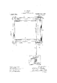
- Figure 1 is a front elevation of the jogger showing in broken lines a railway tie mold mounted thereon.
- Fig. 2 is an end elevation of the jogger.
- Fig. 3 is a top plan View.
- the jogger comprises a frame 4 in which is mounted a cam shaft 5 carrying cams 6 and driven by a motor 7.
- Two oscillating arms S, 9, are pivotally mounted at the rear end of the main frame on pivot pins S', 9', and these arl-ns project forwardly to engage the upper ends of the posts 10. 1l. being guided between the posts l2, 13, and the plates 10', 11, fastened to the posts 1Q, 13, and the frame.
- plates '14 are fastened and each of these plates has a downwardly extending projection 15 at its rear end.
- the cams 6 are fastened on a drive shaft 5 so that when the high point of the other cam will he down and these cams are arranged to engage the projections 15 on the plates 14.
- the mold 16 which may be of any suitable size and shape for making any desired article, is rested in suitable guide plates 17' on the oscillating arms 8, 9, at the forward ends thereof, and it may be tilled with the point of one cam is up the high concrete mixture before or after its is placed in position on the jogger.
- the cams engage the projections 15 and raise and lower the arms S, 9, alternately, thereby imparting an oscillating movement to the arms.
- the high point of the cam passes beyond the projection 15 the arm falls until it engages the post, thereby imparting a violent jar to the mold, especially at that part thereof immediately above the arm which falls.
- This is repeated in rapid succession, first at one end of the mold and then at the other end and l have found that good results are obtained by driving the shaft at the rate of two hundred revolutions per minute, thereby imparting four hundred jars per minute to the mold.
- This violent jarring of the mold causes the stone aggregate therein to settle in a compact mass with the mortar intimately distributed throughout the mass.
- My improved machine is simple in construction and easy to operate and it works the concrete mass in a novel manner and produces at comparatively low cost a molded concrete article.
- a railway tie of great strength amlsolidity ha ving tho stone aggregate compacted therein in a solid mass and the voids between the stones completely filled with the cement mortar.
- the posts 10. l1. may be adjusted vertically to vary the limit of the downward movement of the arms Q. 9. and thereby Patented Aug. 5, 19.13.
- slots 18 are provided in the posts 10, 11, to accommodateA the bolts 19 which fasten the plates4 10', 11 to the posts 12, 18, and shims 20 ofvarious sizes arefplaced on the frame beneath the posts 10, 11. 10, 11, can be moved vertically and rela,- tively to the posts12, 13 and the plates 10', 11 and the shims will sustain the posts 10,
- a jogger of the character described thel combination of a pair of arms capable of movement about a point remote from their front ends and a mold containing a -their front ends, a mold containing a concrete mixture resting on the -forward ends of the arms, and means for oscillating said arms alternately to impart to said mold an endwise oscillat-ion ⁇ land a movement in the arc of a circle.
Landscapes
- Engineering & Computer Science (AREA)
- Mechanical Engineering (AREA)
- Moulds, Cores, Or Mandrels (AREA)
- Devices For Post-Treatments, Processing, Supply, Discharge, And Other Processes (AREA)
Description
A. J. BATES;
- JoGGB. APPLICATION FILED DEU. 1, 1911.
Patented Aug. 5, 1913.
Z SHEETS-SHEET 1.
I: .u ,t ...RWM -w lll -HHHHHU N i. |l @mi E. BATES,
GER.
APPLoATIoN FILED DE01; 1911.
entran stares rarest oratori.
ALBERT J. BATES, OF CHICAGO, ILLINOIS.
JOGGER.
Specification of Letters Patent.
Application led December 1, 1911;. Serial No. 663,297.
To all fui/10m t maw concern Be it known that l, ALBERT J. Barns, a citizen of the United States, residing at Chicago, in the county of Cook and State of Illinois, have invented new and useful lmprovcments in Joggers, of which the following is a speciiic'ation.
In making railway ties and other articles of concrete it is desirable to secure the best results, to completely ll all the vo-ids between the stones with a mortar consisting' of cement and sand, and in order to lessen the cost of manufacture it is further desirable to use as much of the broken stone as possible, thereby decreasing the quantity of cement required.
The object of the present invention is to provide a jogger for settling, precipitating and solidifying the freshly mixed concrete in the mold by subjecting the mold to a succession of violent jars and at the same time imparting to the mold oscillations which cause the mortar to slush lengthwise and sidewise within the mold.
In the accompanying drawings illustrating a simple embodiment of the invention. Figure 1 is a front elevation of the jogger showing in broken lines a railway tie mold mounted thereon. Fig. 2 is an end elevation of the jogger. Fig. 3 is a top plan View.
The jogger comprises a frame 4 in which is mounted a cam shaft 5 carrying cams 6 and driven by a motor 7. Two oscillating arms S, 9, are pivotally mounted at the rear end of the main frame on pivot pins S', 9', and these arl-ns project forwardly to engage the upper ends of the posts 10. 1l. being guided between the posts l2, 13, and the plates 10', 11, fastened to the posts 1Q, 13, and the frame. On the underside of each of the oscillatingr arms, `near the forward end thereof, plates '14 are fastened and each of these plates has a downwardly extending projection 15 at its rear end. The cams 6 are fastened on a drive shaft 5 so that when the high point of the other cam will he down and these cams are arranged to engage the projections 15 on the plates 14.
The mold 16, which may be of any suitable size and shape for making any desired article, is rested in suitable guide plates 17' on the oscillating arms 8, 9, at the forward ends thereof, and it may be tilled with the point of one cam is up the high concrete mixture before or after its is placed in position on the jogger.
ln practice, the cams engage the projections 15 and raise and lower the arms S, 9, alternately, thereby imparting an oscillating movement to the arms. lVhen the high point of the cam passes beyond the projection 15 the arm falls until it engages the post, thereby imparting a violent jar to the mold, especially at that part thereof immediately above the arm which falls. This is repeated in rapid succession, first at one end of the mold and then at the other end and l have found that good results are obtained by driving the shaft at the rate of two hundred revolutions per minute, thereby imparting four hundred jars per minute to the mold. This violent jarring of the mold causes the stone aggregate therein to settle in a compact mass with the mortar intimately distributed throughout the mass.
It will be observed that during the jarring movement of the mold it is also subjected to an endwise and a sidewise oscillation, as indicated in broken lines in Fig. 2, and thisl double oscillation causes the mortar to slush cndwi e and sidewise of the mold whereby it is thoroughly distributed through the mass of stone and completely fills all the voids between the stones. The jarring causes the stone aggregate to precipitate through the mortar until it comes in contact either with thc bottom of the mold or with stone which has already reached a fixed position in the mold. This movement of the stone displaces its equivalent involume of the mortar and the latter rises in the mold until finally the mold is filled with stone and all the voids are filled with mortar. The jarring also breaks any air bubbles which may exist in thcconcrcte and forces the air to escape upwardly through the mortar to' the atmosphere.
My improved machine is simple in construction and easy to operate and it works the concrete mass in a novel manner and produces at comparatively low cost a molded concrete article. such as a railway tie, of great strength amlsolidity ha ving tho stone aggregate compacted therein in a solid mass and the voids between the stones completely filled with the cement mortar.
The posts 10. l1. may be adjusted vertically to vary the limit of the downward movement of the arms Q. 9. and thereby Patented Aug. 5, 19.13.
' control the degree of the jar imparted to the mold and its contents. For this purpose slots 18 are provided in the posts 10, 11, to accommodateA the bolts 19 which fasten the plates4 10', 11 to the posts 12, 18, and shims 20 ofvarious sizes arefplaced on the frame beneath the posts 10, 11. 10, 11, can be moved vertically and rela,- tively to the posts12, 13 and the plates 10', 11 and the shims will sustain the posts 10,
11 in their adjusted position.
I claim:
1. In a jogger of the character described, thel combination of a pair of arms capable of movement about a point remote from their front ends and a mold containing a -their front ends, a mold containing a concrete mixture resting on the -forward ends of the arms, and means for oscillating said arms alternately to impart to said mold an endwise oscillat-ion `land a movement in the arc of a circle.
3.- In a jogger of the character described, the combination of a pair of arms capable of -movement about a point remote from their front ends, a ymold vcontaining a .concrete mixture resting upon their forwardv ends, supports and guides for the forward ends ofthe arms, and cam devices operating beneath the arms to raise the arms alternately above their supports and permit them Thus the posts to drop with a violent jar against the supports.
5L. In a jogger of the character described, the combination of a pair of arms capable of movement about a point remote from their front ends, a mold containing a concrete mixture rest-ing upon their forward ends, supports and guides for the arms at their forward ends, projections beneath the arms, cams arranged to engage said projectionsto lift the arms alternately and permit them to drop with a violent jar against their supports, and means for operating the cams. Y
5. In a jogger of the character described, the combination of a pair of arms capable of movement about a point remote from their front ends,a mold containing a concrete mixture resting upon their forward end, cam devices operating beneath the arms to raise the arms alternately above their supports and permit them to drop with a vio* for raising and lowering the said supports.
6. In a jogger of the character described,
the combination of a pair of arms capable of movement about a point remote from their front ends, a mold containing a concrete mixture restingv upontheir forward -lent jar against their supports, and means to said mold an endwiseoscillation anda movement in the arc of a circle.
ALBERT J. BATES. .n
Priority Applications (1)
| Application Number | Priority Date | Filing Date | Title |
|---|---|---|---|
| US66329711A US1069656A (en) | 1911-12-01 | 1911-12-01 | Jogger. |
Applications Claiming Priority (1)
| Application Number | Priority Date | Filing Date | Title |
|---|---|---|---|
| US66329711A US1069656A (en) | 1911-12-01 | 1911-12-01 | Jogger. |
Publications (1)
| Publication Number | Publication Date |
|---|---|
| US1069656A true US1069656A (en) | 1913-08-05 |
Family
ID=3137893
Family Applications (1)
| Application Number | Title | Priority Date | Filing Date |
|---|---|---|---|
| US66329711A Expired - Lifetime US1069656A (en) | 1911-12-01 | 1911-12-01 | Jogger. |
Country Status (1)
| Country | Link |
|---|---|
| US (1) | US1069656A (en) |
-
1911
- 1911-12-01 US US66329711A patent/US1069656A/en not_active Expired - Lifetime
Similar Documents
| Publication | Publication Date | Title |
|---|---|---|
| US2255343A (en) | Apparatus for making concrete pavements | |
| US1069656A (en) | Jogger. | |
| US2077356A (en) | Method of and apparatus for laying reenforced concrete | |
| US2382458A (en) | Apparatus and method for molding concrete blocks | |
| US1860481A (en) | Apparatus for handling molders' sand | |
| US1062949A (en) | Method of treating concrete mixtures. | |
| US594731A (en) | Machine for driving tie-plates | |
| US1493732A (en) | Concrete-block-forming machine | |
| US2134361A (en) | Method of producing plastic concrete | |
| US1885774A (en) | Clay pouring apparatus | |
| US1632286A (en) | Concrete-molding machine | |
| CN108342947A (en) | stone crushing equipment for road construction | |
| US3127657A (en) | Concrete block making machine | |
| US2392568A (en) | Method of forming silicious bodies | |
| US1719989A (en) | Method of and apparatus for assembling insulators | |
| US1058227A (en) | Molding-machine. | |
| US1346390A (en) | Apparatus for gathering and conveying material | |
| US1203482A (en) | Concrete-tamper. | |
| US2219986A (en) | Tamping and/or mixing machine | |
| US765424A (en) | Concrete-block mold. | |
| US1280032A (en) | Conveyer. | |
| US895964A (en) | Machine for tamping railroad-ties. | |
| US1586A (en) | Hoese-poweb fob dbiviwg jvcachineey | |
| US602112A (en) | Tamping-machine | |
| DE805858C (en) | Ruettelform machine for the production of artificial stones |