US10696533B2 - Remote regulator pressure adjustment tool and method using same - Google Patents
Remote regulator pressure adjustment tool and method using same Download PDFInfo
- Publication number
- US10696533B2 US10696533B2 US15/488,319 US201715488319A US10696533B2 US 10696533 B2 US10696533 B2 US 10696533B2 US 201715488319 A US201715488319 A US 201715488319A US 10696533 B2 US10696533 B2 US 10696533B2
- Authority
- US
- United States
- Prior art keywords
- pressure
- bore
- regulator
- adjuster piston
- adjustment knob
- Prior art date
- Legal status (The legal status is an assumption and is not a legal conclusion. Google has not performed a legal analysis and makes no representation as to the accuracy of the status listed.)
- Active
Links
Images


Classifications
-
- B—PERFORMING OPERATIONS; TRANSPORTING
- B67—OPENING, CLOSING OR CLEANING BOTTLES, JARS OR SIMILAR CONTAINERS; LIQUID HANDLING
- B67D—DISPENSING, DELIVERING OR TRANSFERRING LIQUIDS, NOT OTHERWISE PROVIDED FOR
- B67D1/00—Apparatus or devices for dispensing beverages on draught
- B67D1/08—Details
- B67D1/12—Flow or pressure control devices or systems, e.g. valves, gas pressure control, level control in storage containers
- B67D1/1252—Gas pressure control means, e.g. for maintaining proper carbonation
-
- B—PERFORMING OPERATIONS; TRANSPORTING
- B67—OPENING, CLOSING OR CLEANING BOTTLES, JARS OR SIMILAR CONTAINERS; LIQUID HANDLING
- B67D—DISPENSING, DELIVERING OR TRANSFERRING LIQUIDS, NOT OTHERWISE PROVIDED FOR
- B67D1/00—Apparatus or devices for dispensing beverages on draught
- B67D1/04—Apparatus utilising compressed air or other gas acting directly or indirectly on beverages in storage containers
-
- B—PERFORMING OPERATIONS; TRANSPORTING
- B67—OPENING, CLOSING OR CLEANING BOTTLES, JARS OR SIMILAR CONTAINERS; LIQUID HANDLING
- B67D—DISPENSING, DELIVERING OR TRANSFERRING LIQUIDS, NOT OTHERWISE PROVIDED FOR
- B67D1/00—Apparatus or devices for dispensing beverages on draught
- B67D1/08—Details
- B67D1/0829—Keg connection means
- B67D1/0831—Keg connection means combined with valves
- B67D1/0835—Keg connection means combined with valves with one valve
-
- B—PERFORMING OPERATIONS; TRANSPORTING
- B67—OPENING, CLOSING OR CLEANING BOTTLES, JARS OR SIMILAR CONTAINERS; LIQUID HANDLING
- B67D—DISPENSING, DELIVERING OR TRANSFERRING LIQUIDS, NOT OTHERWISE PROVIDED FOR
- B67D1/00—Apparatus or devices for dispensing beverages on draught
- B67D1/08—Details
- B67D1/0829—Keg connection means
- B67D1/0841—Details
- B67D1/0851—Details composed of a piston and ram assembly, e.g. tappet
-
- B—PERFORMING OPERATIONS; TRANSPORTING
- B67—OPENING, CLOSING OR CLEANING BOTTLES, JARS OR SIMILAR CONTAINERS; LIQUID HANDLING
- B67D—DISPENSING, DELIVERING OR TRANSFERRING LIQUIDS, NOT OTHERWISE PROVIDED FOR
- B67D1/00—Apparatus or devices for dispensing beverages on draught
- B67D1/08—Details
- B67D1/12—Flow or pressure control devices or systems, e.g. valves, gas pressure control, level control in storage containers
- B67D1/14—Reducing valves or control taps
-
- F—MECHANICAL ENGINEERING; LIGHTING; HEATING; WEAPONS; BLASTING
- F17—STORING OR DISTRIBUTING GASES OR LIQUIDS
- F17C—VESSELS FOR CONTAINING OR STORING COMPRESSED, LIQUEFIED OR SOLIDIFIED GASES; FIXED-CAPACITY GAS-HOLDERS; FILLING VESSELS WITH, OR DISCHARGING FROM VESSELS, COMPRESSED, LIQUEFIED, OR SOLIDIFIED GASES
- F17C13/00—Details of vessels or of the filling or discharging of vessels
-
- G—PHYSICS
- G05—CONTROLLING; REGULATING
- G05D—SYSTEMS FOR CONTROLLING OR REGULATING NON-ELECTRIC VARIABLES
- G05D16/00—Control of fluid pressure
- G05D16/04—Control of fluid pressure without auxiliary power
- G05D16/10—Control of fluid pressure without auxiliary power the sensing element being a piston or plunger
- G05D16/103—Control of fluid pressure without auxiliary power the sensing element being a piston or plunger the sensing element placed between the inlet and outlet
- G05D16/106—Sleeve-like sensing elements; Sensing elements surrounded by the flow path
-
- B—PERFORMING OPERATIONS; TRANSPORTING
- B67—OPENING, CLOSING OR CLEANING BOTTLES, JARS OR SIMILAR CONTAINERS; LIQUID HANDLING
- B67D—DISPENSING, DELIVERING OR TRANSFERRING LIQUIDS, NOT OTHERWISE PROVIDED FOR
- B67D1/00—Apparatus or devices for dispensing beverages on draught
- B67D1/08—Details
- B67D1/0801—Details of beverage containers, e.g. casks, kegs
- B67D2001/0822—Pressurised rigid containers, e.g. kegs, figals
- B67D2001/0824—Pressurised rigid containers, e.g. kegs, figals with dip tubes
Definitions
- Applicants' disclosure relates to an apparatus for testing and adjusting a remote pressure regulator disclosed in the U.S. Non-Provisional patent application Ser. No. 14/990,673 and a method to utilize that apparatus.
- a plurality of beer kegs receive pressurized CO 2 gas from a single, high pressure source.
- a source regulator is often interconnected to the output end of the CO 2 source, wherein that source regulator reduces the source pressure from hundreds/thousands of psi to a line pressure of about 35-50 psi. That same line pressure is utilized to dispense a plurality of differing beers from a corresponding plurality of individual beer kegs.
- the current disclosure is directed to a remote regulator adjustment tool that can be used to adjust an output pressure of a remote pressure regulator.
- that remote regulator is removeably attached to a keg coupler.
- the remote regulator pressure adjustment tool comprises a housing formed to include a first bore extending therethrough, an adjustor piston movably disposed within the first bore, and an adjustment knob interconnected to the adjustor piston.
- the adjustor piston contains a threaded aperture extending inwardly from a proximal end thereof A plurality of alignments keys are disposed on a distal end of the adjustor piston.
- the adjustment knob is attached to a threaded shaft extending outwardly from the adjustor piston, wherein the threading on the threaded shaft mates with the threading form in the threaded aperture.
- the adjustor piston moves downwardly in the bore.
- the adjustor piston moves upwardly in the bore.
- the remote regulator comprises an adjustor cap in contact with a spring. When that spring is compressed, the output pressure of an attached regulator increases. When the spring is elongated, the output pressure of an attached regulator decreases.
- the adjustor cap is formed to include a plurality of key slots, wherein the alignment keys on the adjuster piston releaseably insert into those key slots formed in the adjuster cap.
- the remote regulator adjustment tool comprises a pressure gauge.
- the pressure gauge is in fluid communication with the first bore. Therefore, the pressure gauge can measure the dispense pressure of a remote regulator.
- the output pressure of the remote regulator may be referred to as a “dispense pressure” and/or a “pour pressure.”
- the remote regulator adjustment tool comprises a pressure release assembly, which includes a second housing formed to include a threaded end and a second bore extending therethrough, a spring disposed within the second bore, a gasket disposed over a distal end of the second bore, a push rod extending through said gasket and in physical contact with the spring, and a button attached to a distal end of the push rod.
- This pressure release assembly maintains pressure within the adjustment tool when the button is disposed in a first position, and releases pressure from the adjustment tool when the button is disposed in a second position.
- FIG. 1A illustrates a side view of a remote regulator adjustment tool 100 ;
- FIG. 1B is a cross-sectional view illustrating components comprising the remote regulator adjustment tool 100 in FIG. 1A ;
- FIG. 2A shows a remote regulator 200 in combination with a hex nut 310 ;
- FIG. 2B is a cross-sectional view illustrating components comprising the remote regulator adjustment tool 100 and a remote regulator 200 ;
- FIG. 2C illustrates one embodiment of the disposition of a pressure relief assembly 140 ;
- FIG. 2D is a cross-sectional view illustrating components comprising the embodiment of the remote regulator adjustment tool 100 in FIG. 2C ;
- FIG. 3A is an exploded view of one embodiment of the remote regulator adjustment tool 100 ;
- FIG. 3B is an exploded view of another embodiment of the remote regulator adjustment tool 100 ;
- FIG. 4A illustrates one embodiment of Applicants' remote regulator 200 ;
- FIG. 4B is a cross-sectional view illustrating components comprising Applicants' remote regulator 200 ;
- FIG. 5A is an exploded view of the remote regulator 200 ;
- FIG. 5B illustrates a top view of a adjustor cap 500 of the remote regulator 200 ;
- FIG. 5C is a top view of the adjustor cap 500 ;
- FIG. 6 illustrates a prior art keg coupler 300
- FIG. 7 illustrates the components comprising keg coupler 300 ;
- FIG. 8 illustrates keg coupler 300 releaseably attached to a beer keg 400 ;
- FIG. 9A illustrates a hex nut and tail piece components of keg coupler 300 ;
- FIG. 9B illustrates hex nut 310 separately
- FIG. 9C illustrates tail piece 320 separately
- FIG. 10 illustrates Applicants' keg coupler 1000 ;
- FIG. 11 illustrates Applicants' remote regulator in combination with Applicants' adjustment tool comprising an integral controller 1200 ;
- FIG. 12 illustrates controller 1200
- FIG. 13 illustrates Applicants' remote regulator in combination with Applicants' adjustment tool comprising a Schrader valve attachment stage
- FIG. 14 illustrates Applicants' regulator 1400 which comprises a Schrader valve in fluid communication with a regulator output stage.
- CO 2 gas is supplied in a variety of cylinder sizes ranging from about 30 pounds to about 150 pounds and containing about 10 to about 60 pounds of gas, respectively.
- the pressure in such cylinders ranges from about 750 PSIG at 72 F to about 1800 PSIG at about 122 F.
- a source regulator attached to the CO 2 cylinder reduces the output pressure to an intermediate pressure of about 20 PSIG to about 35 PSIG.
- Applicants' remote regulator described herein receives CO 2 gas having a pressure of about 20-35 PSIG from a primary regulator, and reduces that pressure to about 5-18 PSIG.
- Individual dispense pressures are recommended for various brands/types of draught beer plus altitude, temperature, and system length require additional push pressure.
- FIG. 8 gas flows in and beer flows out of a keg through a coupler 300 . While this device has many casual names in beer cellars around the country, the industry adopted the term “coupler” as the standard term for the device.
- FIG. 6 illustrates a Sankey “D” coupler.
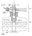
- FIG. 7 illustrates a cut-away view of a Sankey “D” coupler thereby illustrating the components therein.
- FIG. 8 illustrates a Sankey “D” coupler releaseably mounted on a beer keg.
- Kegs are pressurized vessels. Nearly all modern kegs use some form of Sankey valve and stem. There are two main types of Sankey valves and corresponding keg necks: “drop-in,” and threaded. Drop-in Sankey valves are held in place by a lock ring or circlip. The lock ring and valve should never be removed in the field. Very rarely a lock ring can fail, possibly loosening the valve, creating a potentially dangerous situation. Threaded Sankey valves screw into the neck of the keg.
- a probe on the bottom depresses a ball or poppet in the key valve, allowing CO 2 or mixed gas to enter the keg thereby applying pressure to the beer. This forces the beer to travel up the down tube (spear) and drive the beer to the faucet.
- the coupler is attached to a jumper or a beer line 310 ( FIG. 8 ).
- Couplers include one of two types of one-way valves, namely a Thomas valve and/or a check valve.
- a Thomas valve allows CO 2 to flow into the keg but prevents the beer from backing up into the gas line if gas pressure drops. This protects the gas regulators from damage.
- a check valve prevents beer from the beer line flowing out through the coupler. This prevents beer spillage in keg tapping areas.
- keg coupler 300 further comprises an integral pressure relief valve. If excessive gas pressure were applied to a keg, this valve would open to prevent damage to the keg and coupler. The valve can also be opened manually, and this should be done periodically to test the safety relief valve. The manual release usually looks like a small metal pin fitted with a wire ring. To test the valve, pull on the ring to slide the pin a short distance out of the coupler and release a small amount of gas.
- FIG. 9A illustrates Sankey “D” coupler 300 comprising a tail piece 320 and a hex nut 310 .
- FIG. 9B illustrates hex nut 310 .
- Hex nut 310 is formed to include a threaded aperture 316 extending therethrough.
- Hex nut 310 further comprises an annular lip 312 extending inwardly into threaded aperture 316 .
- the hex nut aperture comprises a diameter 314 at the annular lips 312 .
- FIG. 9C illustrates tail piece 320 .
- Tail piece 320 comprises an annular base 322 .
- Annular base comprises a diameter 324 .
- Diameter 324 is greater an diameter 314 of annular lip 312 on hex nut 310 ( FIG. 9B ).
- FIG. 4A illustrates one embodiment of Applicants' remote regulator 200 .
- remote regulator 200 comprises a cylindrical body 410 and an integral tail piece 430 .
- Applicants' remote regulator 200 further comprises an annular lip 420 on a proximal end and an integral tail piece 430 on a distal end.
- annular lip 420 comprises a diameter 440 , wherein diameter 440 is greater than diameter 314 of annular lip 312 on hex nut 310 ( FIG. 9B ).
- FIG. 10 illustrates Applicants' keg coupler 1000 which includes Applicants' remote regulator 200 releaseably attached to Sankey “D” keg coupler.
- hex nut 310 is removed from prior art Sankey keg coupler 300
- tail piece 320 is removed from hex nut 310 .
- the distal end of Applicants' remote regulator is inserted into and through hex nut 310 until annular lip 420 is in contact with annular lip 312 .
- Hex nut 310 is then releaseably attached to Sankey keg coupler 300 to give Applicants' keg coupler 1000 ( FIG. 10 ).
- FIG. 4B illustrates one embodiment of Applicants' remote regulator 200 .
- Regulator 200 comprises distal portion 412 which includes integral tail piece 432 .
- Distal portion 412 comprises an input section for Applicants' remote regulator 200 .
- Portion 434 comprises a high pressure area in regulator 200 .
- Compression spring 414 determines the regulated output pressure in portion 424 . This regulated output pressure corresponds to the “pour pressure” set for that remote regulator. When spring 414 is compressed, the regulated output pressure in portion 424 increases; when compression spring 414 is elongated, the regulated output pressure in portion 424 decreases.
- FIGS. 1A, 1B, 3A, and 3B illustrate embodiments of Applicants remote regulator adjustment tool 100 , which is used to test and adjust the pour pressure of remote regulator 200 .
- FIG. 2B illustrates assembly 600 which comprises Applicants' remote regulator 200 releaseably attached to Applicants' remote regulator adjustment tool 100 .
- the remote regulator adjustment tool 100 comprises an adjustor piston 114 , a housing 110 , the adjustor piston 114 moveably disposed within the housing 110 , a pressure relief assembly 140 , and a pressure gauge 130 . Additionally, a distal end 190 ( FIGS. 1A and 1B ) of housing 110 comprises a threaded connector 150 ( FIGS. 1A and 1B ) to attach to Applicants' remote regulator. To ensure an air-tight attachment between the remote regulator adjustment tool and the remote regulator, a gasket 180 ( FIGS. 2C and 3A ) is disposed at distal end 190 of the housing.
- FIG. 2B illustrates remote regulator adjustment tool 100 releaseably attached to Applicants' remote regulator 200 .
- Hex nut 310 ( FIGS. 2A, 9B ) is used to attach remote regulator 200 to remote regulator adjustment tool 100 .
- distal end of Applicants' remote regulator 200 is inserted into and through hex nut 310 until annular lip 420 is in contact with annular lip 312 .
- Hex nut 310 is then releaseably attached to threading 150 formed on distal end 190 of remote regulator adjustment tool 100 , such that threaded portion 150 of Applicants' remote regulator adjustment tool 100 meshes with the threaded aperture 316 ( FIG. 9B ) defining the aperture extending through hex nut 310 .
- a bore 112 extends therethrough housing 110 and adjustor piston 114 is movably disposed within bore 112 .
- adjustor piston 114 is formed to include a threaded aperture extending inwardly from a proximal end thereof and an adjustment knob 120 is attached to a distal end of threaded shaft 122 ( FIGS. 3A and 3B ).
- Threaded shaft 122 FIG. 3A
- Threaded aperture 115 FIGS. 2B and 3A
- Alignment keys 160 and 162 are disposed on distal end of adjustor piston 114 .
- the pressure relief assembly 140 is located on an opposite side of the pressure gauge 130 ( FIGS. 2C, 2D and 3A ). In other embodiments, the pressure relief assembly 140 is located on the same side of the pressure gauge 130 ( FIGS. 1A, 1B, 2B and 3B ).
- the pressure relief assembly 140 a located on the opposite side of the pressure gauge 130 , comprises a housing 141 a formed to include a threaded end and a bore 142 a ( FIG. 3A ) therethrough. Gasket 146 a is disposed over a distal err of bore 142 a. Push rod 148 a extends though gasket 146 a, and physically contacts a spring 144 a.
- Button 149 a is attached to push rod 148 a. Pushing button 149 a releases pressure within the remote regulator adjustment tool.
- Pressure gauge 130 measures pressure when the remote regulator adjustment tool alone, or when the remote regulator adjustment tool in combination with Applicants' remote regulator is connected to a source of pressurized gas.
- the pressure relief assembly 140 located on the same side of the pressure gauge 130 , comprises a housing 141 b ( FIG. 1B ) formed to include a threaded end and a bore 142 b ( FIG. 3B ) therethrough. Gasket 146 b is disposed over a distal end of bore 142 b. Pushing button 149 b releases pressure within the remote regulator adjustment tool.
- Applicants' remote regulator 200 comprises an adjustor cap 500 , which is formed to include key slots 510 and 512 . Further, key slots 510 and 512 are configured so that alignment keys 160 and 162 ( FIGS. 1A and 1B ) can be removeably inserted therein. In the illustrated embodiment of FIG. 2B , when remote regulator 200 is releaseably attached to remote regulator adjustment tool 100 , alignment keys 160 and 162 are removeably inserted into key slots 510 and 512 . After the alignment keys are disposed in the key slots, the pour pressure can be adjusted by rotating the adjustment knob 120 . Rather, a distal end of threaded shaft 122 ( FIGS. 3A and 3B ) is attached to motor 1120 . Assembly 1100 further comprises controller 1200 . Controller 1200 operates motor 1120 .
- buttons 149 a and 149 b can be depressed to release the pressure within adjustment tool 100 .
- the adjusted pressure can be read from pressure gauge 130 . If the adjusted pressure differs from a desired pressure, adjustment knob 120 can be rotated clock-wise or counter clock-wise in small increments until the desired pour pressure is reached. In certain embodiments, rotating the adjustment knob 120 in small increments allows finite and gradual adjustment of the desired pour pressure. This feature is suitable for pouring many different beverages, which have different desired pour pressures.
- an ideal range of pour pressure for wine is about 4 to 5 psi; an ideal range of pour pressure for beer is about 10-15 psi; an ideal range of pour pressure for beer (low draw) is about 20 to 25 psi; and an ideal range of pour pressure for nitro is about 30 to 35 psi.
- the examples are not limiting and a user is able to rotate the adjustment knob 120 to reach any desired pour pressure.
- assembly 1100 comprises regulator 200 in combination with a modified adjustment tool 1101 .
- Adjustment tool 1100 differs from adjustment tool 100 in that pressure relief assembly 140 is replaced by output portion 1105 .
- Pressurized gas from a primary regulator enters assembly 1100 at input end 1107 . That one-time reduced-pressure gas first travels through regulator 200 , where gas pressure is again reduced.
- Assembly 1100 further comprises a housing 1110 .
- Assembly 1101 does not comprise adjustment knob 120 ( FIGS. 3A and 3B ). Rather, a distal end of threaded shaft 122 is attached to motor 1120 .
- Assembly 1100 further comprises controller 1200 . Controller 1200 operates motor 1120 .
- Assembly 1100 further comprises a first pressure sensor 1201 in input potion 1107 .
- Communication link 1202 interconnects first pressure sensor 1201 and controller 1200 .
- Assembly 1100 further comprises a second pressure sensor 1203 in output potion 1105 .
- Communication link 1204 interconnects second pressure sensor 1203 and controller 1200 .
- controller 1200 comprises processor 1210 , memory 1220 interconnected with processor 1210 via communication link 1225 , optional Blue Tooth module 1230 interconnected with processor 1210 via communication link 1235 , optional RFID module 1240 interconnected with processor 1210 via communication link 1245 , and optional “WI-FI” module 1250 interconnected with processor 1210 via communication link 1255 .
- microcode 1222 , instructions 1224 , and database 1226 are encoded in memory 1220 .
- memory 1220 comprises non-volatile memory.
- memory 1220 comprises battery backed up RAM, a magnetic hard disk assembly, an optical disk assembly, and/or electronic memory.
- electroactive memory Applicants mean a PROM, EPROM, EEPROM, SMARTMEDIA, FLASHMEDIA, and the like.
- Processor 1210 uses microcode 1222 to operate controller 1230 .
- Processor 1210 uses microcode 1222 , instructions 1224 , and database 1226 , to operate Blue Tooth module 1230 , RFID module 1240 , WI-FI module 1250 , motor 1120 , and pressure sensors 1201 and 1203 .
- a desired output pressure in output stage 1105 ( FIG. 11 ) is encoded in database 1226 .
- Controller 1200 continuously monitors the incoming pressure using pressure sensor 1201 , and output pressure using sensor 1203 . If a measured output pressure is greater than the encoded desired output pressure, then controller 1200 causes motor 1120 to cause threaded shaft 122 to move outwardly, while continuously monitoring the output pressure. If a measured output pressure is less than the encoded desired output pressure, then controller 1200 causes motor 1120 to cause threaded shaft to move inwardly, while continuously monitoring the output pressure. When the measured output pressure equals the desired output pressure, then controller does not cause motor 1110 to rotate threaded shaft 122 in either direction.
- assembly 1300 is a modification of adjustment tool 100 ( FIG. 2C ).
- the pressure relief assembly 140 a of adjustment tool 100 is replaced with assembly 1310 .
- Assembly 1310 comprises a threaded coupler 1312 which can be releaseably attached to housing 110 after removing pressure relief assembly 140 a.
- Assembly 1310 further comprises a flexible tube 1314 and a Schrader valve attachment 1316 .
- assembly 1300 can be used as a pressure gauge to check the air pressure within any device comprising a Schrader valve, including without limitation, bicycle tires, automobile tires, and the like.
- regulator 1400 comprises the features of regulator 200 ( FIG. 2A ) in combination with Schrader valve assembly 1410 which is in fluid communication with low pressure, output stage 740 .
- Assembly 1400 comprises a tubular member 1412 and threaded end 1414 .
- a pressure gauge can be releaseably attached to threaded end 1414 to monitor the pressure within regulator 1400 which regulator 1400 remains in place and in operation.
Landscapes
- Physics & Mathematics (AREA)
- Engineering & Computer Science (AREA)
- Fluid Mechanics (AREA)
- General Physics & Mathematics (AREA)
- Automation & Control Theory (AREA)
- Mechanical Engineering (AREA)
- General Engineering & Computer Science (AREA)
- Control Of Fluid Pressure (AREA)
Abstract
Description
Claims (6)
Priority Applications (28)
| Application Number | Priority Date | Filing Date | Title |
|---|---|---|---|
| US15/488,319 US10696533B2 (en) | 2015-01-08 | 2017-04-14 | Remote regulator pressure adjustment tool and method using same |
| NZ755956A NZ755956B2 (en) | 2017-04-14 | 2018-04-11 | Remote regulator pressure adjustment tool and method using the same |
| EP19208212.1A EP3650405B1 (en) | 2017-04-14 | 2018-04-11 | Remote regulator pressure adjustment tool and method using the same |
| RU2019117861A RU2711677C1 (en) | 2017-04-14 | 2018-04-11 | Instrument for adjusting pressure of a remote controller and method of using such a tool |
| KR1020197027719A KR102329694B1 (en) | 2017-04-14 | 2018-04-11 | Remote Regulator Pressure Adjustment Tool and How to Use It |
| ES19208212T ES2899129T3 (en) | 2017-04-14 | 2018-04-11 | Remote regulator pressure adjustment tool and method of using same |
| EP18722298.9A EP3529203B1 (en) | 2017-04-14 | 2018-04-11 | Remote regulator pressure adjustment tool and method using the same |
| PL19208212T PL3650405T3 (en) | 2017-04-14 | 2018-04-11 | Remote regulator pressure adjustment tool and method using the same |
| CA3130665A CA3130665A1 (en) | 2017-04-14 | 2018-04-11 | Remote regulator pressure adjustment tool and method using same |
| UAA201909280A UA125260C2 (en) | 2017-04-14 | 2018-04-11 | Remote regulator pressure adjustment tool and method using the same |
| AU2018251812A AU2018251812B2 (en) | 2017-04-14 | 2018-04-11 | Remote regulator pressure adjustment tool and method using the same |
| LTEP19208212.1T LT3650405T (en) | 2017-04-14 | 2018-04-11 | Remote regulator pressure adjustment tool and method using the same |
| BR112019021202A BR112019021202A2 (en) | 2017-04-14 | 2018-04-11 | apparatus for adjusting an outlet pressure of a pressure regulator, set and method for adjusting an outlet pressure of a remote pressure regulator |
| HRP20211844TT HRP20211844T1 (en) | 2017-04-14 | 2018-04-11 | Remote regulator pressure adjustment tool and method using the same |
| CA3044876A CA3044876A1 (en) | 2017-04-14 | 2018-04-11 | Remote regulator pressure adjustment tool and method using same |
| MX2019010703A MX2019010703A (en) | 2017-04-14 | 2018-04-11 | Remote regulator pressure adjustment tool and method using the same. |
| PCT/US2018/027169 WO2018191417A1 (en) | 2017-04-14 | 2018-04-11 | Remote regulator pressure adjustment tool and method using the same |
| ES18722298T ES2882190T3 (en) | 2017-04-14 | 2018-04-11 | Remote Regulator Pressure Setting Tool and Method of Using It |
| MA046595A MA46595A (en) | 2017-04-14 | 2018-04-11 | REMOTE REGULATOR PRESSURE ADJUSTMENT TOOL AND USER PROCESS |
| HRP20211299TT HRP20211299T1 (en) | 2017-04-14 | 2018-04-11 | REMOTE PRESSURE REGULATOR ADJUSTMENT TOOL AND PROCEDURE FOR USING IT |
| LTEP18722298.9T LT3529203T (en) | 2017-04-14 | 2018-04-11 | Remote regulator pressure adjustment tool and method using the same |
| DK18722298.9T DK3529203T3 (en) | 2017-04-14 | 2018-04-11 | TOOLS FOR SETTING A REMOTE CONTROLLER AND PROCEDURE FOR USING THE SAME |
| PL18722298T PL3529203T3 (en) | 2017-04-14 | 2018-04-11 | Remote regulator pressure adjustment tool and method using the same |
| CN201880004830.8A CN110114299B (en) | 2017-04-14 | 2018-04-11 | Remote regulator pressure adjustment tool and method of use |
| CN201911204013.XA CN110817782B (en) | 2017-04-14 | 2018-04-11 | Assembly and method to adjust the output pressure of a remote pressure regulator |
| ZA2019/05166A ZA201905166B (en) | 2017-04-14 | 2019-08-05 | Remote regulator pressure adjustment tool and method using the same |
| ZA2020/00317A ZA202000317B (en) | 2017-04-14 | 2020-01-16 | Remote regulator pressure adjustment tool and method using the same |
| AU2020217359A AU2020217359B2 (en) | 2017-04-14 | 2020-08-11 | Remote Regulator Pressure Adjustment Tool and Method Using the Same |
Applications Claiming Priority (3)
| Application Number | Priority Date | Filing Date | Title |
|---|---|---|---|
| US201562101257P | 2015-01-08 | 2015-01-08 | |
| US14/990,673 US9828227B2 (en) | 2015-01-08 | 2016-01-07 | Keg coupler with secondary pressure regulator and systems using same |
| US15/488,319 US10696533B2 (en) | 2015-01-08 | 2017-04-14 | Remote regulator pressure adjustment tool and method using same |
Related Parent Applications (1)
| Application Number | Title | Priority Date | Filing Date |
|---|---|---|---|
| US14/990,673 Continuation-In-Part US9828227B2 (en) | 2015-01-08 | 2016-01-07 | Keg coupler with secondary pressure regulator and systems using same |
Publications (2)
| Publication Number | Publication Date |
|---|---|
| US20170260037A1 US20170260037A1 (en) | 2017-09-14 |
| US10696533B2 true US10696533B2 (en) | 2020-06-30 |
Family
ID=59788468
Family Applications (1)
| Application Number | Title | Priority Date | Filing Date |
|---|---|---|---|
| US15/488,319 Active US10696533B2 (en) | 2015-01-08 | 2017-04-14 | Remote regulator pressure adjustment tool and method using same |
Country Status (1)
| Country | Link |
|---|---|
| US (1) | US10696533B2 (en) |
Cited By (4)
| Publication number | Priority date | Publication date | Assignee | Title |
|---|---|---|---|---|
| US20230137829A1 (en) * | 2021-11-03 | 2023-05-04 | Craft Standard Enterprises, Inc. | Apparatus, system and method for mixing liquid in a beverage container |
| US20230331535A1 (en) * | 2021-09-10 | 2023-10-19 | Adrian Rivera | Pressurized Beverage Dispenser |
| US20240302851A1 (en) * | 2021-03-17 | 2024-09-12 | Neoperl Gmbh | Pressure limiter |
| US20260109588A1 (en) * | 2024-10-23 | 2026-04-23 | Richard Eklund | Keg system |
Families Citing this family (7)
| Publication number | Priority date | Publication date | Assignee | Title |
|---|---|---|---|---|
| KR102272693B1 (en) * | 2013-07-11 | 2021-07-05 | 어드밴스드 테크놀러지 머티리얼즈, 인코포레이티드 | Apparatus and methods for filling and dispensing liquids |
| JP6342973B2 (en) * | 2016-11-24 | 2018-06-13 | ファナック株式会社 | Manual pulse generator |
| US10506308B1 (en) * | 2018-08-01 | 2019-12-10 | B. United International Inc. | Closed vessel monitoring |
| US11117792B2 (en) * | 2019-03-05 | 2021-09-14 | Hunter Caputo | Keg sensor assemblies |
| US11207486B2 (en) | 2020-05-29 | 2021-12-28 | Legacy US Inc. | Fluid mixing apparatus such as a ventilator |
| US11318272B2 (en) * | 2020-05-29 | 2022-05-03 | Legacy US Inc. | Selective attachment device with multiple fluid sources for maintaining positive fluid pressure |
| US11007342B1 (en) * | 2020-05-29 | 2021-05-18 | Legacy US Inc. | Fluid mixing apparatus such as a ventilator |
Citations (29)
| Publication number | Priority date | Publication date | Assignee | Title |
|---|---|---|---|---|
| US746755A (en) | 1902-11-22 | 1903-12-15 | Ira H Spencer | Pressure-regulator. |
| US879604A (en) | 1907-04-12 | 1908-02-18 | John Wawrzinski | Beer-tap. |
| GB191410858A (en) | 1913-05-03 | 1915-07-02 | Arthur Schmid | Improved Method and Appliance for the Retail Pouring Out of Fermentable Liquids kept under Pressure. |
| US2020492A (en) | 1934-05-24 | 1935-11-12 | Zahm & Nagel Co Inc | Gas pressure regulator |
| US3129730A (en) | 1961-07-14 | 1964-04-21 | John F Simon | Tapping system for liquid container or the like |
| US3200994A (en) | 1963-04-16 | 1965-08-17 | Evelyn Levinson | Positive-pressure controlled-atmosphere liquid dispenser |
| US3698417A (en) | 1970-03-11 | 1972-10-17 | Republic Corp | Keg tapping device with automatic gas shutoff valve |
| US3933282A (en) | 1974-02-04 | 1976-01-20 | Hoff-Stevens, Inc. | Universal tavern unit for keg tapping device |
| US4011971A (en) | 1975-12-29 | 1977-03-15 | Edward R. Haydon | Device for dispensing liquids from a sealed container and for preserving undispensed portions thereof |
| BE885849A (en) | 1979-10-23 | 1981-02-16 | Lambrechts Pvba Konstr | INSTALLATION FOR TAPING LIQUIDS FROM BARRELS |
| GB2094939A (en) | 1981-03-12 | 1982-09-22 | Distillers The Co Carbon Dioxi | Gas pressure regulator assembly |
| US4364493A (en) | 1979-08-15 | 1982-12-21 | Arthur Guinness Son And Company (Park Royal) Limited | Beverage dispensing system |
| US4484695A (en) | 1980-02-07 | 1984-11-27 | Draft Systems, Inc. | Safety pressure reducing regulator |
| CN1036627A (en) | 1988-03-08 | 1989-10-25 | 国家研究发展公司 | Pressure regulator |
| US4898205A (en) | 1987-03-17 | 1990-02-06 | Western/Scott Fetzer Company | Stem regulator |
| US4928850A (en) | 1988-06-01 | 1990-05-29 | Mcdantim, Inc. | Gas blending apparatus |
| US5244118A (en) | 1992-03-02 | 1993-09-14 | Fallon Merton R | Gas blending apparatus |
| US5513831A (en) * | 1995-05-17 | 1996-05-07 | Seward; Alfred L. | Safety control knob for hot water valve |
| US5836483A (en) | 1997-02-05 | 1998-11-17 | Aerotech Dental Systems, Inc. | Self-regulating fluid dispensing cap with safety pressure relief valve for dental/medical unit fluid bottles |
| CN1239464A (en) | 1997-09-04 | 1999-12-22 | 皇家菲利浦电子有限公司 | Beverage Dispensing Equipment |
| US6637516B1 (en) * | 2001-11-26 | 2003-10-28 | Anthony R. Boyd | High torque and high capacity rotatable center core and floatable sealed body assemblies with universal RAM applications and method |
| US6874521B1 (en) | 1999-11-12 | 2005-04-05 | Vent-Matic Company, Inc. | High to low gas flow regulator |
| US20060011664A1 (en) | 2004-07-15 | 2006-01-19 | Hammond Jerry G | Portable beer keg tap and dispenser |
| US20090194564A1 (en) | 2006-07-20 | 2009-08-06 | Hoshizaki Denki Kabushiki Kaisha | Beverage dispensing apparatus |
| WO2010124036A1 (en) | 2009-04-21 | 2010-10-28 | Maugham Christopher M | Regulators and power supply systems |
| US7836911B2 (en) | 2007-05-18 | 2010-11-23 | Glen M. Arnott | Gas pressure regulator with a valve and piston assembly |
| WO2013006655A1 (en) | 2011-07-06 | 2013-01-10 | Gitlin Jr David Allen | Keg tapping system |
| EP2720105A2 (en) | 2012-10-12 | 2014-04-16 | Illinois Tool Works Inc. | Multi-stage pressure regulator and method for fluid pressure regulation |
| WO2016112323A1 (en) | 2015-01-08 | 2016-07-14 | Illinois Tool Works Inc. | Keg coupler with secondary pressure regulator and systems using same |
-
2017
- 2017-04-14 US US15/488,319 patent/US10696533B2/en active Active
Patent Citations (30)
| Publication number | Priority date | Publication date | Assignee | Title |
|---|---|---|---|---|
| US746755A (en) | 1902-11-22 | 1903-12-15 | Ira H Spencer | Pressure-regulator. |
| US879604A (en) | 1907-04-12 | 1908-02-18 | John Wawrzinski | Beer-tap. |
| GB191410858A (en) | 1913-05-03 | 1915-07-02 | Arthur Schmid | Improved Method and Appliance for the Retail Pouring Out of Fermentable Liquids kept under Pressure. |
| US2020492A (en) | 1934-05-24 | 1935-11-12 | Zahm & Nagel Co Inc | Gas pressure regulator |
| US3129730A (en) | 1961-07-14 | 1964-04-21 | John F Simon | Tapping system for liquid container or the like |
| US3200994A (en) | 1963-04-16 | 1965-08-17 | Evelyn Levinson | Positive-pressure controlled-atmosphere liquid dispenser |
| US3698417A (en) | 1970-03-11 | 1972-10-17 | Republic Corp | Keg tapping device with automatic gas shutoff valve |
| US3933282A (en) | 1974-02-04 | 1976-01-20 | Hoff-Stevens, Inc. | Universal tavern unit for keg tapping device |
| US4011971A (en) | 1975-12-29 | 1977-03-15 | Edward R. Haydon | Device for dispensing liquids from a sealed container and for preserving undispensed portions thereof |
| US4364493A (en) | 1979-08-15 | 1982-12-21 | Arthur Guinness Son And Company (Park Royal) Limited | Beverage dispensing system |
| BE885849A (en) | 1979-10-23 | 1981-02-16 | Lambrechts Pvba Konstr | INSTALLATION FOR TAPING LIQUIDS FROM BARRELS |
| US4484695A (en) | 1980-02-07 | 1984-11-27 | Draft Systems, Inc. | Safety pressure reducing regulator |
| GB2094939A (en) | 1981-03-12 | 1982-09-22 | Distillers The Co Carbon Dioxi | Gas pressure regulator assembly |
| US4898205A (en) | 1987-03-17 | 1990-02-06 | Western/Scott Fetzer Company | Stem regulator |
| CN1036627A (en) | 1988-03-08 | 1989-10-25 | 国家研究发展公司 | Pressure regulator |
| US4928850A (en) | 1988-06-01 | 1990-05-29 | Mcdantim, Inc. | Gas blending apparatus |
| US5244118A (en) | 1992-03-02 | 1993-09-14 | Fallon Merton R | Gas blending apparatus |
| US5513831A (en) * | 1995-05-17 | 1996-05-07 | Seward; Alfred L. | Safety control knob for hot water valve |
| US5836483A (en) | 1997-02-05 | 1998-11-17 | Aerotech Dental Systems, Inc. | Self-regulating fluid dispensing cap with safety pressure relief valve for dental/medical unit fluid bottles |
| CN1239464A (en) | 1997-09-04 | 1999-12-22 | 皇家菲利浦电子有限公司 | Beverage Dispensing Equipment |
| US6874521B1 (en) | 1999-11-12 | 2005-04-05 | Vent-Matic Company, Inc. | High to low gas flow regulator |
| US6637516B1 (en) * | 2001-11-26 | 2003-10-28 | Anthony R. Boyd | High torque and high capacity rotatable center core and floatable sealed body assemblies with universal RAM applications and method |
| US20060011664A1 (en) | 2004-07-15 | 2006-01-19 | Hammond Jerry G | Portable beer keg tap and dispenser |
| US20090194564A1 (en) | 2006-07-20 | 2009-08-06 | Hoshizaki Denki Kabushiki Kaisha | Beverage dispensing apparatus |
| US7836911B2 (en) | 2007-05-18 | 2010-11-23 | Glen M. Arnott | Gas pressure regulator with a valve and piston assembly |
| WO2010124036A1 (en) | 2009-04-21 | 2010-10-28 | Maugham Christopher M | Regulators and power supply systems |
| WO2013006655A1 (en) | 2011-07-06 | 2013-01-10 | Gitlin Jr David Allen | Keg tapping system |
| EP2720105A2 (en) | 2012-10-12 | 2014-04-16 | Illinois Tool Works Inc. | Multi-stage pressure regulator and method for fluid pressure regulation |
| EP2720105B1 (en) | 2012-10-12 | 2019-12-04 | Illinois Tool Works Inc. | Multi-stage pressure regulator. |
| WO2016112323A1 (en) | 2015-01-08 | 2016-07-14 | Illinois Tool Works Inc. | Keg coupler with secondary pressure regulator and systems using same |
Non-Patent Citations (6)
| Title |
|---|
| European Search Report 19208212.1. |
| International Search Report and Written Opinion issued in related International Application No. PCT/US2018/027169, dated Aug. 24, 2018, 2018, 19 pages. |
| IPRP PCT/US2018/027169. |
| Office Action, application 201880004830.8; dated Nov. 7, 2019. |
| Office Action, dated Apr. 2020, AU2018251812. |
| Partial International Search issued in related International Application No. PCT/US2018/027169, dated Jun. 29, 2018, 2 pages. |
Cited By (5)
| Publication number | Priority date | Publication date | Assignee | Title |
|---|---|---|---|---|
| US20240302851A1 (en) * | 2021-03-17 | 2024-09-12 | Neoperl Gmbh | Pressure limiter |
| US20230331535A1 (en) * | 2021-09-10 | 2023-10-19 | Adrian Rivera | Pressurized Beverage Dispenser |
| US20230137829A1 (en) * | 2021-11-03 | 2023-05-04 | Craft Standard Enterprises, Inc. | Apparatus, system and method for mixing liquid in a beverage container |
| US11807513B2 (en) * | 2021-11-03 | 2023-11-07 | Craft Standard Enterprises, Inc. | Apparatus, system and method for mixing liquid in a beverage container |
| US20260109588A1 (en) * | 2024-10-23 | 2026-04-23 | Richard Eklund | Keg system |
Also Published As
| Publication number | Publication date |
|---|---|
| US20170260037A1 (en) | 2017-09-14 |
Similar Documents
| Publication | Publication Date | Title |
|---|---|---|
| US10696533B2 (en) | Remote regulator pressure adjustment tool and method using same | |
| EP3242851B1 (en) | Keg coupler with secondary pressure regulator and systems using same | |
| US7401622B2 (en) | Modular pressure regulator | |
| US20090078321A1 (en) | Gas pressure regulator having a regulator cap for a bayonet engagement with the regulator body | |
| US4095727A (en) | Apparatus for dispensing a liquid from a container | |
| GB2127941A (en) | Improved safety pressure reducing regulator | |
| US3698417A (en) | Keg tapping device with automatic gas shutoff valve | |
| US20160251210A1 (en) | Pressure regulation in beverage containers | |
| US8640732B1 (en) | High pressure inlet regulator | |
| US7181953B1 (en) | Moisture detector assembly | |
| AU611430B2 (en) | A fluid pressure control valve and a system which includes such a valve | |
| AU2020217359B2 (en) | Remote Regulator Pressure Adjustment Tool and Method Using the Same | |
| NZ755956B2 (en) | Remote regulator pressure adjustment tool and method using the same | |
| WO2008130684A1 (en) | Connector with screw valve | |
| US20060011366A1 (en) | Inlet valve for pneumatic tool | |
| US9328870B2 (en) | Flow regulator for nitrogen purging, system and method | |
| AU2019100195A4 (en) | Dispensing of a beverage in a portable situation involving a keg holding the beverage | |
| US343596A (en) | Doeb moeeis | |
| GB2125518A (en) | Gas inlet device for pressure vessel | |
| GB2161543A (en) | Pressure-reducing adapter for siphon apparatuses |
Legal Events
| Date | Code | Title | Description |
|---|---|---|---|
| STPP | Information on status: patent application and granting procedure in general |
Free format text: FINAL REJECTION MAILED |
|
| AS | Assignment |
Owner name: LEGACY PRT, LLC, CALIFORNIA Free format text: ASSIGNMENT OF ASSIGNORS INTEREST;ASSIGNOR:ILLINOIS TOOL WORKS INC.;REEL/FRAME:048938/0308 Effective date: 20190410 Owner name: LEGACY US LLC, CALIFORNIA Free format text: ASSIGNMENT OF ASSIGNORS INTEREST;ASSIGNOR:LEGACY PRT, LLC;REEL/FRAME:048938/0328 Effective date: 20190417 |
|
| FEPP | Fee payment procedure |
Free format text: ENTITY STATUS SET TO SMALL (ORIGINAL EVENT CODE: SMAL); ENTITY STATUS OF PATENT OWNER: SMALL ENTITY |
|
| STPP | Information on status: patent application and granting procedure in general |
Free format text: DOCKETED NEW CASE - READY FOR EXAMINATION |
|
| STPP | Information on status: patent application and granting procedure in general |
Free format text: NON FINAL ACTION MAILED |
|
| STPP | Information on status: patent application and granting procedure in general |
Free format text: RESPONSE TO NON-FINAL OFFICE ACTION ENTERED AND FORWARDED TO EXAMINER |
|
| STPP | Information on status: patent application and granting procedure in general |
Free format text: NOTICE OF ALLOWANCE MAILED -- APPLICATION RECEIVED IN OFFICE OF PUBLICATIONS |
|
| STPP | Information on status: patent application and granting procedure in general |
Free format text: NOTICE OF ALLOWANCE MAILED -- APPLICATION RECEIVED IN OFFICE OF PUBLICATIONS |
|
| STPP | Information on status: patent application and granting procedure in general |
Free format text: PUBLICATIONS -- ISSUE FEE PAYMENT VERIFIED |
|
| STCF | Information on status: patent grant |
Free format text: PATENTED CASE |
|
| STCF | Information on status: patent grant |
Free format text: PATENTED CASE |
|
| MAFP | Maintenance fee payment |
Free format text: PAYMENT OF MAINTENANCE FEE, 4TH YR, SMALL ENTITY (ORIGINAL EVENT CODE: M2551); ENTITY STATUS OF PATENT OWNER: SMALL ENTITY Year of fee payment: 4 |