US10696429B2 - Dual condenser loop heat pipe for satellites with sun-normal radiators - Google Patents
Dual condenser loop heat pipe for satellites with sun-normal radiators Download PDFInfo
- Publication number
- US10696429B2 US10696429B2 US15/424,599 US201715424599A US10696429B2 US 10696429 B2 US10696429 B2 US 10696429B2 US 201715424599 A US201715424599 A US 201715424599A US 10696429 B2 US10696429 B2 US 10696429B2
- Authority
- US
- United States
- Prior art keywords
- radiator
- satellite
- east
- west
- north
- Prior art date
- Legal status (The legal status is an assumption and is not a legal conclusion. Google has not performed a legal analysis and makes no representation as to the accuracy of the status listed.)
- Active, expires
Links
Images


Classifications
-
- F—MECHANICAL ENGINEERING; LIGHTING; HEATING; WEAPONS; BLASTING
- F28—HEAT EXCHANGE IN GENERAL
- F28D—HEAT-EXCHANGE APPARATUS, NOT PROVIDED FOR IN ANOTHER SUBCLASS, IN WHICH THE HEAT-EXCHANGE MEDIA DO NOT COME INTO DIRECT CONTACT
- F28D15/00—Heat-exchange apparatus with the intermediate heat-transfer medium in closed tubes passing into or through the conduit walls ; Heat-exchange apparatus employing intermediate heat-transfer medium or bodies
- F28D15/02—Heat-exchange apparatus with the intermediate heat-transfer medium in closed tubes passing into or through the conduit walls ; Heat-exchange apparatus employing intermediate heat-transfer medium or bodies in which the medium condenses and evaporates, e.g. heat pipes
- F28D15/0266—Heat-exchange apparatus with the intermediate heat-transfer medium in closed tubes passing into or through the conduit walls ; Heat-exchange apparatus employing intermediate heat-transfer medium or bodies in which the medium condenses and evaporates, e.g. heat pipes with separate evaporating and condensing chambers connected by at least one conduit; Loop-type heat pipes; with multiple or common evaporating or condensing chambers
-
- B—PERFORMING OPERATIONS; TRANSPORTING
- B64—AIRCRAFT; AVIATION; COSMONAUTICS
- B64G—COSMONAUTICS; VEHICLES OR EQUIPMENT THEREFOR
- B64G1/00—Cosmonautic vehicles
- B64G1/22—Parts of, or equipment specially adapted for fitting in or to, cosmonautic vehicles
- B64G1/46—Arrangements or adaptations of devices for control of environment or living conditions
- B64G1/50—Arrangements or adaptations of devices for control of environment or living conditions for temperature control
- B64G1/503—Radiator panels
-
- B—PERFORMING OPERATIONS; TRANSPORTING
- B64—AIRCRAFT; AVIATION; COSMONAUTICS
- B64G—COSMONAUTICS; VEHICLES OR EQUIPMENT THEREFOR
- B64G1/00—Cosmonautic vehicles
- B64G1/22—Parts of, or equipment specially adapted for fitting in or to, cosmonautic vehicles
- B64G1/46—Arrangements or adaptations of devices for control of environment or living conditions
- B64G1/50—Arrangements or adaptations of devices for control of environment or living conditions for temperature control
- B64G1/506—Heat pipes
-
- B—PERFORMING OPERATIONS; TRANSPORTING
- B64—AIRCRAFT; AVIATION; COSMONAUTICS
- B64G—COSMONAUTICS; VEHICLES OR EQUIPMENT THEREFOR
- B64G1/00—Cosmonautic vehicles
- B64G1/22—Parts of, or equipment specially adapted for fitting in or to, cosmonautic vehicles
- B64G1/52—Protection, safety or emergency devices; Survival aids
- B64G1/58—Thermal protection, e.g. heat shields
-
- F—MECHANICAL ENGINEERING; LIGHTING; HEATING; WEAPONS; BLASTING
- F28—HEAT EXCHANGE IN GENERAL
- F28D—HEAT-EXCHANGE APPARATUS, NOT PROVIDED FOR IN ANOTHER SUBCLASS, IN WHICH THE HEAT-EXCHANGE MEDIA DO NOT COME INTO DIRECT CONTACT
- F28D15/00—Heat-exchange apparatus with the intermediate heat-transfer medium in closed tubes passing into or through the conduit walls ; Heat-exchange apparatus employing intermediate heat-transfer medium or bodies
- F28D15/02—Heat-exchange apparatus with the intermediate heat-transfer medium in closed tubes passing into or through the conduit walls ; Heat-exchange apparatus employing intermediate heat-transfer medium or bodies in which the medium condenses and evaporates, e.g. heat pipes
- F28D15/0241—Heat-exchange apparatus with the intermediate heat-transfer medium in closed tubes passing into or through the conduit walls ; Heat-exchange apparatus employing intermediate heat-transfer medium or bodies in which the medium condenses and evaporates, e.g. heat pipes the tubes being flexible
-
- F—MECHANICAL ENGINEERING; LIGHTING; HEATING; WEAPONS; BLASTING
- F28—HEAT EXCHANGE IN GENERAL
- F28D—HEAT-EXCHANGE APPARATUS, NOT PROVIDED FOR IN ANOTHER SUBCLASS, IN WHICH THE HEAT-EXCHANGE MEDIA DO NOT COME INTO DIRECT CONTACT
- F28D15/00—Heat-exchange apparatus with the intermediate heat-transfer medium in closed tubes passing into or through the conduit walls ; Heat-exchange apparatus employing intermediate heat-transfer medium or bodies
- F28D15/02—Heat-exchange apparatus with the intermediate heat-transfer medium in closed tubes passing into or through the conduit walls ; Heat-exchange apparatus employing intermediate heat-transfer medium or bodies in which the medium condenses and evaporates, e.g. heat pipes
- F28D15/0275—Arrangements for coupling heat-pipes together or with other structures, e.g. with base blocks; Heat pipe cores
-
- H—ELECTRICITY
- H10—SEMICONDUCTOR DEVICES; ELECTRIC SOLID-STATE DEVICES NOT OTHERWISE PROVIDED FOR
- H10W—GENERIC PACKAGES, INTERCONNECTIONS, CONNECTORS OR OTHER CONSTRUCTIONAL DETAILS OF DEVICES COVERED BY CLASS H10
- H10W40/00—Arrangements for thermal protection or thermal control
- H10W40/70—Fillings or auxiliary members in containers or in encapsulations for thermal protection or control
- H10W40/73—Fillings or auxiliary members in containers or in encapsulations for thermal protection or control for cooling by change of state
-
- F—MECHANICAL ENGINEERING; LIGHTING; HEATING; WEAPONS; BLASTING
- F28—HEAT EXCHANGE IN GENERAL
- F28D—HEAT-EXCHANGE APPARATUS, NOT PROVIDED FOR IN ANOTHER SUBCLASS, IN WHICH THE HEAT-EXCHANGE MEDIA DO NOT COME INTO DIRECT CONTACT
- F28D21/00—Heat-exchange apparatus not covered by any of the groups F28D1/00 - F28D20/00
- F28D2021/0019—Other heat exchangers for particular applications; Heat exchange systems not otherwise provided for
- F28D2021/0021—Other heat exchangers for particular applications; Heat exchange systems not otherwise provided for for aircrafts or cosmonautics
Definitions
- the present disclosure relates to dual condenser loop heat pipes.
- it relates to dual condenser loop heat pipes for satellites with sun-normal radiators.
- a method for a satellite thermal management system comprises heating, in an evaporator, a liquid to convert the liquid to a vapor.
- the method further comprises passively circulating within tubing, from the evaporator, the vapor to a first radiator not illuminated by a sun and to a second radiator illuminated by the sun.
- the method comprises converting the vapor to the liquid when the vapor is within the first radiator not illuminated by the sun.
- the method comprises passively circulating within the tubing, from the first radiator not illuminated by the sun, the liquid to the evaporator.
- the first radiator is mounted to an east side of a satellite, and the second radiator is mounted to a west side of the satellite. In some embodiments, the first radiator is mounted to a west side of a satellite, and the second radiator is mounted to an east side of the satellite.
- the liquid is circulated within the tubing, from the first radiator not illuminated by the sun, to the evaporator via a vapor blocking tee.
- the vapor is circulated within the tubing, from the evaporator, to the first radiator not illuminated by the sun and to the second radiator illuminated by the sun via a vapor tee.
- the liquid is a refrigerant.
- At least one portion of the tubing comprises a flexible segment.
- the flexible segment is a flex hose.
- the evaporator is mounted within an interior of a satellite.
- the liquid is heated by heat conducting from a payload of a satellite.
- a satellite thermal management system (i.e. a dual condenser loop heat pipe) comprises an evaporator to heat a liquid to convert the liquid to a vapor.
- the system further comprises a first radiator not illuminated by the sun. In one or more embodiments, when the vapor is within the first radiator not illuminated by the sun, the vapor is converted to the liquid.
- the system also comprises a second radiator illuminated by the sun. Further, the system comprises tubing to passively circulate the vapor from the evaporator to the first radiator not illuminated by the sun and to the second radiator illuminated by the sun, and to passively circulate the liquid from the first radiator not illuminated by the sun to the evaporator. In one or more embodiments, the tubing connects the evaporator to the first radiator not illuminated by the sun and to the second radiator illuminated by the sun.
- a method of manufacturing a satellite thermal management system comprises installing south tubing in an interior of a satellite bus proximate a south facing side of the satellite bus. The method further comprises installing north tubing in the interior of the satellite bus proximate a north facing side of the satellite bus. Also, the method comprises connecting a south evaporator to the south tubing, and a north evaporator to the north tubing. In addition, the method comprises mating the satellite bus to a satellite payload to form an integrated satellite.
- the method comprises connecting a north west radiator to a north west corner of the integrated satellite, a north east radiator to a north east corner of the integrated satellite, a south west radiator to a south west corner of the integrated satellite, and a south east radiator to a south east corner of the integrated satellite.
- the method comprises connecting the south tubing to the south west radiator and the south east radiator.
- the method comprises connecting the north tubing to the north west radiator and the north east radiator.
- the method comprises rotating the north west radiator and the south west radiator such that the north west radiator and the south west radiator both lie on a west facing side of the integrated satellite.
- the method comprises rotating the north east radiator and the south east radiator such that the north east radiator and the south east radiator both lie on an east facing side of the integrated satellite.
- a method of installing a satellite thermal management system into an integrated satellite comprises installing a south side dual condenser loop heat pipe within an interior of a satellite bus proximate a south facing side of the satellite bus.
- the south side dual condenser loop heat pipe comprises a south evaporator, a south west radiator, and a south east radiator.
- the method further comprises installing a north side dual condenser loop heat pipe within the interior of the satellite bus proximate a north facing side of the satellite bus.
- the north side dual condenser loop heat pipe comprises a north evaporator, a north west radiator, and a north east radiator.
- the method comprises rotating the south west radiator, the south east radiator, the north west radiator, and the north east radiator such that both faces of each of the south west radiator, the south east radiator, the north west radiator, and the north east radiator are located away from all faces of the satellite bus.
- the method comprises mating the satellite bus to a satellite payload to form the integrated satellite.
- the method comprises connecting, during the mating of the satellite bus to the satellite payload, the south evaporator to a south side constant conductance heat pipe within the satellite payload.
- the method comprises connecting, during the mating of the satellite bus to the satellite payload, the north evaporator to a north side constant conductance heat pipe within the satellite payload.
- the method comprises rotating the north west radiator and the south west radiator such that the north west radiator and the south west radiator both lie on a west facing side of the integrated satellite. Additionally, the method comprises rotating the north east radiator and the south east radiator such that the north east radiator and the south east radiator both lie on an east facing side of the integrated satellite. Also, the method comprises attaching the north west radiator and the south west radiator to the west facing side of the integrated satellite. Further, the method comprises attaching the north east radiator and the south east radiator to the east facing side of the integrated satellite.
- the south side dual condenser loop heat pipe comprises at least one portion of tubing that comprises a flexible segment. In some embodiments, the north side dual condenser loop heat pipe comprises at least one portion of tubing that comprises a flexible segment.
- the south side dual condenser loop heat pipe is pressurized with a refrigerant prior to being installed within the interior of the satellite bus. In some embodiments, the north side dual condenser loop heat pipe is pressurized with a refrigerant prior to being installed within the interior of the satellite bus.
- FIG. 1A is a diagram showing an exemplary satellite employing the disclosed satellite thermal management system, where the satellite is in a stowed position, in accordance with at least one embodiment of the present disclosure.
- FIG. 1B is a diagram showing an exemplary satellite employing the disclosed satellite thermal management system, where the satellite is in a deployed position, in accordance with at least one embodiment of the present disclosure.
- FIG. 2A is a diagram showing an exemplary satellite employing the disclosed satellite thermal management system, where the satellite is in a stowed position, in accordance with at least one embodiment of the present disclosure.
- FIG. 2B is a diagram showing an exemplary satellite employing the disclosed satellite thermal management system, where the satellite is in a partially deployed position, in accordance with at least one embodiment of the present disclosure.
- FIG. 2C is a diagram showing an exemplary satellite employing the disclosed satellite thermal management system, where the satellite is in a fully deployed position, in accordance with at least one embodiment of the present disclosure.
- FIG. 3A is a schematic diagram showing the disclosed satellite thermal management system (i.e. a dual condenser loop heat pipe), where the east radiator is illuminated by the sun and the west radiator is not illuminated by the sun, in accordance with at least one embodiment of the present disclosure.
- satellite thermal management system i.e. a dual condenser loop heat pipe
- FIG. 3B is a schematic diagram showing the disclosed satellite thermal management system (i.e. a dual condenser loop heat pipe), where the west radiator is illuminated by the sun and the east radiator is not illuminated by the sun, in accordance with at least one embodiment of the present disclosure.
- satellite thermal management system i.e. a dual condenser loop heat pipe
- FIG. 3C is a schematic diagram showing details of an exemplary vapor blocking tee employed by the disclosed satellite thermal management system (i.e. a dual condenser loop heat pipe), in accordance with at least one embodiment of the present disclosure.
- satellite thermal management system i.e. a dual condenser loop heat pipe
- FIG. 4A is a diagram showing the west radiator (mounted on the north side of the west face of the satellite) and the east radiator (mounted on the north side of the east face of the satellite) of the disclosed satellite thermal management system (i.e. the north side dual condenser loop heat pipe), in accordance with at least one embodiment of the present disclosure.
- the disclosed satellite thermal management system i.e. the north side dual condenser loop heat pipe
- FIG. 4B is a diagram showing the west radiator (mounted on the south side of the west face of the satellite) and the east radiator (mounted on the south side of the east face of the satellite) of the disclosed satellite thermal management system (i.e. the south side dual condenser loop heat pipe), in accordance with at least one embodiment of the present disclosure.
- the disclosed satellite thermal management system i.e. the south side dual condenser loop heat pipe
- FIG. 5A is a diagram showing details of the flexible segments of the tubing as shown in FIG. 4A , in accordance with at least one embodiment of the present disclosure.
- FIG. 5B is a diagram showing details of the vapor tee and the vapor blocking tee connections to the tubing as shown in FIG. 4A , in accordance with at least one embodiment of the present disclosure.
- FIG. 6 is a diagram showing a flow chart for the disclosed method for a satellite thermal management system, in accordance with at least one embodiment of the present disclosure.
- FIG. 7 is a graph 700 showing exemplary heat transfer in watts (W) for the east radiator (mounted on the north side of the east face of the satellite) (i.e. NE radiator), the west radiator (mounted on the north side of the west face of the satellite) (i.e. NW radiator), the west radiator (mounted on the south side of the west face of the satellite) (i.e. the SW radiator), and the east radiator (mounted on the south side of the east face of the satellite) (i.e. the SE radiator) over a twenty-four (24) hour period for the disclosed satellite thermal management system, in accordance with at least one embodiment of the present disclosure.
- W heat transfer in watts
- FIG. 8 is a schematic diagram showing the location of the evaporators and vapor blocking tees within the satellite in relation to the payload for the disclosed satellite thermal management system, in accordance with at least one embodiment of the present disclosure.
- FIGS. 9A, 9B, 9C, and 9D together are diagrams depicting the method of installing a satellite thermal management system (i.e. a dual condenser loop heat pipe) into an exemplary integrated satellite, in accordance with at least one embodiment of the present disclosure.
- a satellite thermal management system i.e. a dual condenser loop heat pipe
- FIGS. 10A and 10B together show a flow chart for the disclosed method of installing a satellite thermal management system (i.e. a dual condenser loop heat pipe) into an exemplary integrated satellite, in accordance with at least one embodiment of the present disclosure.
- a satellite thermal management system i.e. a dual condenser loop heat pipe
- the methods and apparatus disclosed herein provide an operative system for dual condenser loop heat pipes for satellites with sun-normal radiators.
- the system of the present disclosure enables heat rejection off of satellite surfaces (i.e. the east and west faces) whose thermal environment is too extreme to be useful to current conventional thermal control systems for satellites.
- the system of the present disclosure enables satellites to reject heat with greater efficiency by utilizing the east and west surfaces of the spacecraft, thereby making the satellites more competitive in the satellite market.
- the system of the present disclosure provides a thermal control technology for use on spacecraft in geosynchronous earth orbit (GEO) or other orbits, such as medium earth orbit (MEO), lower earth orbit (LEO), and super geosynchronous earth orbit (Super GEO).
- GEO geosynchronous earth orbit
- MEO medium earth orbit
- LEO lower earth orbit
- Super GEO super geosynchronous earth orbit
- the disclosed system uses radiating surfaces whose external diurnal thermal environments cause these surfaces to be only minimally useful for heat rejection with the current conventional technology.
- the disclosed system lets these surfaces cool electronics, which require low operating temperatures and small diurnal temperature variation, by use of a fluidic switch (with no moving parts) that responds naturally to its environment. Heat is rejected from either of two radiators, whichever is cooler than the electronics.
- the radiators are oriented such that at least one is in a cool thermal environment at all times.
- conventional systems for thermal control on spacecraft allow for heat generated from on-board electronics to be rejected off of the north and south facing surfaces of the spacecraft.
- the north and south facing surfaces of the spacecraft exhibit a cooler environment than the east and west facing surfaces of the spacecraft.
- These conventional systems for thermal control do not allow for much heat to be rejected off of the east and west facing surfaces of the spacecraft because they are illuminated by the sun at least once per orbit.
- the disclosed system allows for heat to be rejected off of the east and west facing surfaces of the spacecraft, thereby making the spacecraft more thermally efficient.
- the disclosed system employs dual condenser loop heat pipes on the east and west faces of a satellite.
- This present disclosure details the design of such a system including various design and installation options for ease of manufacturing and shipping from the vendor to the satellite manufacturer.
- the present disclosure provides design elements, such as: the routing of the vapor and condensate lines such that they are adjacent to one another, but thermally isolated from each other; a parallel flow condenser relative to a serial flow condenser; cross-coupling with constant conductance heat pipes to the north and south radiators to maximize heat rejection during warmest seasons and to reduce the required heater power; and heater control.
- the system of the present disclosure utilizes east-west panels in combination with dual condenser loop heat pipes (with fluidic-valve-controlled segmentation of coolant flow between the two panels and with flexible portions in the tubing system) coupling the east panel and the west panel to enable assembly in the satellite vehicle.
- dual condenser loop heat pipes to the east and west panels enables rejection of greater payload heat loads on the vehicle.
- segmented parallel flow path tubing patterns within each panel enable partial operation of the east panel or west panel when the panels are partially shaded from the sun.
- payload capacity can be limited by the cooling capacity of the vehicle's radiator panels.
- An increased cooling capacity allows for improved ratios of vehicle size to payload capacity (i.e. allows for smaller vehicles with a greater payload capacity).
- FIG. 1A is a diagram 100 showing an exemplary satellite 130 employing the disclosed satellite thermal management system, where the satellite 130 is in a stowed position, in accordance with at least one embodiment of the present disclosure.
- the satellite 130 comprises a north solar panel 105 , a south solar panel (out of view in figure) 115 , east antenna reflectors 125 , 135 , west antenna reflectors (out of view in figure) 145 , 155 , and nadir antenna reflectors 165 , 175 .
- the north solar panel 105 , the south solar panel (out of view in figure) 115 , east antenna reflectors 125 , 135 , west antenna reflectors (out of view in figure) 145 , 155 , and nadir antenna reflectors 165 , 175 are all shown to be in a stowed position.
- FIG. 1B is a diagram 110 showing an exemplary satellite 140 employing the disclosed satellite thermal management system, where the satellite 140 is in a deployed position, in accordance with at least one embodiment of the present disclosure.
- the satellite 140 comprises a north solar panel 106 , a south solar panel 116 , east antenna reflectors 126 , 136 , west antenna reflectors 146 , 156 , and nadir antenna reflectors 166 , 176 .
- the north solar panel 106 , the south solar panel 116 , east antenna reflectors 126 , 136 , west antenna reflectors 146 , 156 , and nadir antenna reflectors 166 , 176 are all shown to be in a deployed position.
- the satellite 140 comprises an east radiator (mounted on the north side of the satellite 140 ) 180 , an east radiator (mounted on the south side of the satellite 140 ) 181 , a west radiator (mounted on the north side of the satellite 140 ) (out of view in figure) 182 , and a west radiator (mounted on the south side of the satellite 140 ) (out of view in figure) 183 .
- FIG. 2A is a diagram 200 showing an exemplary satellite 205 employing the disclosed satellite thermal management system, where the satellite 205 is in a stowed position, in accordance with at least one embodiment of the present disclosure.
- the satellite 205 comprises a north solar panel 206 , a south solar panel (out of view in figure) 209 , east antenna reflectors 207 , 208 , and west antenna reflectors (out of view in figure) 203 , 204 .
- the north solar panel 206 , the south solar panel (out of view in figure) 209 , east antenna reflectors 207 , 208 , and west antenna reflectors (out of view in figure) 203 , 204 are all shown to be in a stowed position.
- FIG. 2B is a diagram 210 showing an exemplary satellite 215 employing the disclosed satellite thermal management system, where the satellite 215 is in a partially deployed position, in accordance with at least one embodiment of the present disclosure.
- the satellite 215 comprises a north solar panel 216 , a south solar panel (out of view in figure) 219 , east antenna reflectors 217 , 218 , and west antenna reflectors (out of view in figure) 213 , 214 .
- the north solar panel 216 , the south solar panel (out of view in figure) 219 are shown to still be in a stowed position.
- the east antenna reflectors 217 , 218 and the west antenna reflectors 213 , 214 are in a partially deployed position.
- the satellite comprises an east radiator (mounted on the north side of the satellite 215 ) 230 , an east radiator (mounted on the south side of the satellite 215 ) 231 , a west radiator (mounted on the north side of the satellite 215 ) (out of view in figure) 232 , and a west radiator (mounted on the south side of the satellite 215 ) (out of view in figure) 233 .
- FIG. 2C is a diagram 220 showing an exemplary satellite 225 employing the disclosed satellite thermal management system, where the satellite 225 is in a fully deployed position, in accordance with at least one embodiment of the present disclosure.
- the satellite 225 comprises a north solar panel 226 , a south solar panel 229 , east antenna reflectors 227 , 228 , and west antenna reflectors 223 , 224 .
- the north solar panel 226 , the south solar panel 229 , east antenna reflectors 227 , 228 , and west antenna reflectors 223 , 224 are all shown to be in a deployed position.
- the satellite 225 comprises an east radiator (mounted on the north side of the satellite 140 ) 240 , an east radiator (mounted on the south side of the satellite 140 ) 241 , a west radiator (mounted on the north side of the satellite 140 ) (out of view in figure) 242 , and a west radiator (mounted on the south side of the satellite 140 ) (out of view in figure) 243 .
- FIG. 3A is a schematic diagram showing the disclosed satellite thermal management system (i.e. a dual condenser loop heat pipe) 301 , where the east radiator 310 is illuminated by the sun 350 and the west radiator 320 is not illuminated by the sun 350 , in accordance with at least one embodiment of the present disclosure.
- tubing 360 e.g., stainless steel tubing (SST) and/or aluminum tubing
- SST stainless steel tubing
- the tubing 360 connects an evaporator 390 to the east radiator 310 and to the west radiator 320 .
- the east radiator 310 and the west radiator 320 may be mounted to the north side of the satellite; or the east radiator 310 and the west radiator 320 may be mounted to the south side of the satellite.
- liquid i.e. a heat transfer fluid
- a heat transfer fluid e.g., ammonia, propylene, or other similar type of refrigerant
- the liquid is heated in the evaporator 390 by heat conducting from the heat generating electronics of the satellite.
- the liquid is converted to a vapor (e.g., ammonia vapor, propylene vapor, or other similar type of refrigerant vapor).
- the vapor is passively circulated within tubing 360 from the evaporator 390 to the west radiator 320 , which is not illuminated by the sun 350 , and to the east radiator 310 , which is illuminated by the sun 350 via a vapor tee 330 .
- the vapor When the vapor is within tubing 360 of the west radiator 320 not illuminated by the sun 350 , the vapor cools and converts back to a liquid. Then, the liquid passively circulates within tubing 360 from the west radiator 320 to the evaporator 390 via a vapor blocking tee 340 . Then, the process repeats.
- FIG. 3B is a schematic diagram showing the disclosed satellite thermal management system (i.e. a dual condenser loop heat pipe) 302 , where the west radiator 320 is illuminated by the sun 350 and the east radiator 310 is not illuminated by the sun 350 , in accordance with at least one embodiment of the present disclosure in this figure, tubing 360 (e.g., stainless steel tubing) is shown to be run through the east radiator 310 and the west radiator 320 .
- the tubing 360 connects an evaporator 390 to the east radiator 310 and to the west radiator 320 .
- the east radiator 310 and the west radiator 320 may be mounted to the north side of the east and west faces of the satellite; or the east radiator 310 and the west radiator 320 may be mounted to south side of the east and west faces of the satellite.
- liquid i.e. a heat transfer fluid
- a heat transfer fluid e.g., ammonia, propylene, or other similar type of refrigerant
- the liquid is heated in the evaporator 390 by heat conducting from the heat generating electronics of the satellite.
- the liquid is converted to a vapor (e.g., ammonia vapor, propylene vapor, or other similar type of refrigerant vapor).
- the vapor is passively circulated within tubing 360 from the evaporator 390 to the east radiator 310 , which is not illuminated by the sun 350 , and to the west radiator 320 , which is illuminated by the sun 350 via a vapor tee 330 .
- the vapor When the vapor is within tubing 360 of the east radiator 310 not illuminated by the sun 350 , the vapor cools and converts back to a liquid. Then, the liquid passively circulates within tubing 360 from the east radiator 310 to the evaporator 390 via a vapor blocking tee 340 . Then, the process repeats.
- FIG. 3C is a schematic diagram 303 showing details of an exemplary vapor blocking tee 340 employed by the disclosed satellite thermal management system (i.e. a dual condenser loop heat pipe), in accordance with at least one embodiment of the present disclosure.
- the vapor blocking tee 340 allows liquid from the radiator not illuminated by the sun to pass through the vapor blocking tee 340 .
- wetted porous plugs within the vapor blocking tee 340 do not allow the vapor from the radiator illuminated by the sun to pass through the vapor blocking tee 340 .
- FIG. 4A is a diagram showing the west radiator (mounted on the north side of the west face of the satellite) (i.e. NW radiator) 422 and the east radiator (mounted on the north side of the east face of the satellite) (i.e. NE radiator) 420 of the disclosed satellite thermal management system (i.e. the north side dual condenser loop heat pipe) 400 , in accordance with at least one embodiment of the present disclosure.
- the west radiator 422 and the east radiator 420 are shown to both have tubing (i.e. north tubing) 460 running throughout their interior. Portions of the tubing 460 comprise flexible segments (i.e. segments that are able to be bent) 450 , 495 .
- the flexible segments 450 , 495 of the tubing 460 comprise flex hose (e.g., corrugated tubing or braided tubing).
- a vapor tee 440 connects tubing 460 running from both the west radiator 422 and the east radiator 420 .
- a vapor blocking tee 430 connects tubing 460 running from both the west radiator 422 and the east radiator 420 .
- Tubing 460 connects an evaporator (i.e. north evaporator) 490 to the vapor tee 440 and the vapor blocking tee 430 .
- FIG. 4B is a diagram showing the west radiator (mounted on the south side of the west face of the satellite) (i.e. the SW radiator) 423 and the east radiator (mounted on the south side of the east face of the satellite) (i.e. the SE radiator) 421 of the disclosed satellite thermal management system (i.e. the south side dual condenser loop heat pipe) 410 , in accordance with at least one embodiment of the present disclosure.
- the west radiator 423 and the east radiator 421 are shown to both have tubing (i.e. south tubing) 461 running throughout their interior. Portions of the tubing 461 comprise flexible segments (i.e. segments that are able to be bent) 451 , 496 .
- the flexible segments 451 , 496 of the tubing 461 comprise flex hose.
- a vapor tee 441 connects tubing 461 running from both the west radiator 423 and the east radiator 421 .
- a vapor blocking tee 431 connects tubing 461 running from both the west radiator 423 and the east radiator 421 .
- the vapor tee 441 is thermally isolated from the vapor blocking tee 431 .
- Tubing 461 connects an evaporator (i.e. south evaporator) 491 to the vapor tee 441 and the vapor blocking tee 431 .
- FIG. 5A is a diagram 500 showing details of the flexible segments 450 , 495 of the tubing 460 as shown in FIG. 4A , in accordance with at least one embodiment of the present disclosure.
- the diagram 500 shows details of the flexible segments 450 proximate the east radiator (mounted on the north side of the east face of the satellite) (i.e. NE radiator) 420 .
- the flexible segments 450 , 451 (refer to FIG. 4B ) proximate the west radiator (mounted on the north side of the west face of the satellite) (i.e. NW radiator) 422
- the west radiator mounted on the south side of the west face of the satellite) (i.e.
- the SW radiator) 423 , and the east radiator (mounted on the south side of the east face of the satellite) (i.e. the SE radiator) 421 are similar to the flexible segments 450 proximate the east radiator (mounted on the north side of the east face of the satellite) (i.e. NE radiator) 420 (as shown in FIG. 5A ).
- one flexible segment 450 is shown to be a liquid line 501
- another flexible segment 450 is shown to be a vapor line 502 .
- FIG. 5B is a diagram 510 showing details of the vapor tee 440 and the vapor blocking tee 430 connections to the tubing 460 and the flexible segments 495 as shown in FIG. 4A , in accordance with at least one embodiment of the present disclosure.
- the diagram 510 shows details of the tubing 460 connecting to the vapor tee 440 and the vapor blocking tee 430 from the east radiator (mounted on the north side of the east face of the satellite) (i.e. NE radiator) 420 and the west radiator (mounted on the north side of the west face of the satellite) (i.e. NW radiator) 422 .
- the details of the tubing 461 (refer to FIG.
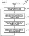
- FIG. 6 is a diagram showing a flow chart for the disclosed method 600 for a satellite thermal management system, in accordance with at least one embodiment of the present disclosure.
- a liquid is heated in an evaporator to convert the liquid to a vapor 620 .
- the vapor is passively circulated within tubing from the evaporator to a first radiator not illuminated by the sun and to a second radiator illuminated by the sun 630 .
- the vapor is converted to a liquid when the vapor is within the first radiator not illuminated by the sun 640 .
- the liquid is passively circulated within the tubing from the first radiator not illuminated by the sun to the evaporator.
- the method 600 proceeds back to the step 620 to be repeated.
- FIG. 7 is a graph 700 showing exemplary heat transfer in watts (W) for the east radiator (mounted on the north side of the east face of the satellite) (i.e. NE radiator) 420 (refer to FIG. 4A ), the west radiator (mounted on the north side of the west face of the satellite) (i.e. NW radiator) 422 (refer to FIG. 4A ), the west radiator (mounted on the south side of the west face of the satellite) (i.e. the SW radiator) 423 (refer to FIG. 4B ), and the east radiator (mounted on the south side of the east face of the satellite) (i.e. the SE radiator) 421 (refer to FIG.
- W heat transfer in watts
- the x-axis represents time after local satellite time (LST) noon, in hours (hr); and the y-axis represents the amount of heat transfer in watts (W).
- the majority of the heat transfer is shown to be occurring on the east radiator (mounted on the south side of the east face of the satellite) (i.e. the SE radiator) 421 and the east radiator (mounted on the north side of the east face of the satellite) (i.e. NE radiator) 420 .
- the majority of the heat transfer is shown to be occurring on the west radiator (mounted on the south side of the west face of the satellite) (i.e. the SW radiator) 423 and the west radiator (mounted on the north side of the west face of the satellite) (i.e. NW radiator) 422 .
- FIG. 8 is a schematic diagram 800 showing the location of the evaporators 490 , 491 , vapor blocking tees 430 , 431 , and vapor tees 440 , 441 within the satellite 810 in relation to a payload 820 (e.g., payload electronics) for the disclosed satellite thermal management system, in accordance with at least one embodiment of the present disclosure.
- a payload 820 e.g., payload electronics
- tubing 460 is shown to be connecting the vapor blocking tee 430 and the vapor tee 440 to the east radiator (mounted on the north side of the east face of the satellite) (i.e.
- NE radiator 420 and the west radiator (mounted on the north side of the west face of the satellite) (i.e. NW radiator) 422 and the evaporator 490 (i.e. north evaporator).
- the vapor blocking tee 430 and the vapor tee 440 are shown to be located within the interior of the satellite 810 proximate the north side of the satellite 810 . It should be noted that in this figure, the vapor blocking tee 430 and the vapor tee 440 appear to be a single unit, however they are actually two distinct separate thermally isolated units, as is shown in FIG. 5B .
- the evaporator 490 is shown to be mounted within the interior of the satellite 810 and proximate the payload (e.g., payload electronics) 820 .
- a north side constant conductance heat pipe 830 is shown to be mounted proximate the payload (e.g., payload electronics) 820 and the evaporator 490 .
- the evaporator 490 is attached (e.g. via a bolt(s)) to the north side constant conductance heat pipe 830 .
- the north side constant conductance heat pipe 830 is oriented within the interior of the satellite 810 such that it combines the east radiator (mounted on the north side of the east face of the satellite) (i.e. NE radiator) 420 and the west radiator (mounted on the north side of the west face of the satellite) (i.e. NW radiator) 422 to the radiator(s) 840 on the north side of the satellite 810 .
- tubing 461 is shown to be connecting the vapor blocking tee 431 and the vapor tee 441 to the east radiator (mounted on the south side of the east face of the satellite) (i.e. the SE radiator) 421 and the west radiator (mounted on the south side of the west face of the satellite) (i.e. the SW radiator) 423 and evaporator 491 (i.e. south evaporator).
- the vapor blocking tee 431 and the vapor tee 441 are shown to be located within the interior of the satellite 810 proximate the south side of the satellite 810 .
- the vapor blocking tee 431 and the vapor tee 441 appear to be a single unit, however they are actually two distinct separate thermally isolated units as is shown, for example, in FIG. 5B .
- the evaporator 491 is shown to be mounted within the interior of the satellite 810 and proximate the payload (e.g., payload electronics) 820 .
- a south side constant conductance heat pipe 831 is shown to be mounted proximate the payload (e.g., payload electronics) 820 and the evaporator 491 .
- the evaporator 491 is attached (e.g. via a bolt(s)) to the south side constant conductance heat pipe 831 .
- the south side constant conductance heat pipe 831 is oriented within the interior of the satellite 810 such that it combines the east radiator (mounted on the south side of the east face of the satellite) (i.e. the SE radiator) 421 and the west radiator (mounted on the south side of the west face of the satellite) (i.e. the SW radiator) 423 to the radiator(s) 841 on the south side of the satellite 810 .
- the payload 820 may be any sort of on-board electronics that generate heat.
- the payload 820 is located in between the constant conductance heat pipe 830 , 831 .
- FIGS. 9A, 9B, 9C, and 9D together are diagrams 901 , 902 , 903 , 904 depicting the method of installing a satellite thermal management system (i.e. a dual condenser loop heat pipe) (refer to 400 of FIG. 4A and 410 of FIG. 4B ) into an exemplary integrated satellite 915 , in accordance with at least one embodiment of the present disclosure.
- a satellite thermal management system i.e. a dual condenser loop heat pipe
- a satellite payload 905 is shown to be mated with a satellite bus 910 to form an integrated satellite (refer to 915 of FIG. 9B ).
- a south side dual condenser loop heat pipe (refer to 410 of FIG. 4B ) and a north side dual condenser loop heat pipe (refer to 400 of FIG. 4A ) are each fully assembled, cleaned, charged with refrigerant, pressurized, and tested.
- the south side dual condenser loop heat pipe (refer to 410 of FIG. 4B ) is installed within an interior of the satellite bus 910 proximate the south facing side of the satellite bus 910 .
- the south side dual condenser loop heat pipe (refer to 410 of FIG. 4B ) comprises a south evaporator (refer to 491 of FIG. 4B ), a south west radiator (refer to 423 of FIG. 4B ), and a south east radiator 421 (also refer to 421 in FIG. 4B ).
- FIG. 9A for the south side dual condenser loop heat pipe (refer to 410 of FIG. 4B ), only the south east radiator 421 is shown. This is because the south evaporator (refer to 491 of FIG. 4B ) and the south west radiator (refer to 423 of FIG. 4B ) are located directly behind the south east radiator 421 .
- the north side dual condenser loop heat pipe (refer to 400 of FIG. 4A ) is installed within the interior of the satellite bus 910 proximate the north facing side of the satellite bus 910 .
- the north side dual condenser loop heat pipe (refer to 400 of FIG. 4A ) comprises a north evaporator (refer to 490 of FIG. 4A ), a north west radiator (refer to 422 of FIG. 4A ), and a north east radiator 420 (also refer to 420 of FIG. 4A ).
- FIG. 9A for the north side dual condenser loop heat pipe (refer to 400 of FIG. 4A ), only the north east radiator 420 is shown. This is because the north evaporator (refer to 490 of FIG. 4A ) and the north west radiator (refer to 422 of FIG. 4A ) are located directly behind the north east radiator 420 .
- the south west radiator (refer to 423 of FIG. 4B ), the south east radiator 421 , the north west radiator (refer to 422 of FIG. 4A ), and the north east radiator 420 are rotated such that both faces of each of the south west radiator (refer to 423 of FIG. 4B ), the south east radiator 421 , the north west radiator (refer to 422 of FIG. 4A ), and the north east radiator 420 are located away from all faces of the satellite bus 910 (e.g., as shown in FIG. 9A , the faces of the north east radiator 420 and the north east radiator 420 are located away from the faces of the satellite bus 910 .
- the portions of the tubing 460 (refer to FIG.
- the satellite payload 905 is mated to the satellite bus 910 to form the integrated satellite (refer to 915 of FIG. 9B ).
- the south evaporator (refer to 491 of FIG. 8 ) is positioned proximate to a south side constant conductance heat pipe (refer to 831 of FIG. 8 ) within the satellite payload 905 .
- the portions of the tubing 461 (refer to FIG.
- FIG. 4B that comprise flexible segments (i.e. segments that are able to be bent) 496 (refer to FIG. 4B ) allow for the positioning of the south evaporator (refer to 491 of FIG. 8 ) to be proximate to the south side constant conductance heat pipe (refer to 831 of FIG. 8 ).
- the south evaporator (refer to 491 of FIG. 8 ) is positioned proximate to the south side constant conductance heat pipe (refer to 831 of FIG. 8 )
- the south evaporator (refer to 491 of FIG. 8 ) is connected (e.g., via a bolt(s)) to the south side constant conductance heat pipe (refer to 831 of FIG. 8 ) within the satellite payload 905 .
- the north evaporator (refer to 490 of FIG. 8 ) is positioned proximate to a north side constant conductance heat pipe (refer to 830 of FIG. 8 ) within the satellite payload 905 .
- the north evaporator (refer to 490 of FIG. 8 ) is positioned proximate to the north side constant conductance heat pipe (refer to 830 of FIG. 8 )
- the north evaporator (refer to 490 of FIG. 8 ) is connected (e.g., via a bolt(s)) to the north side constant conductance heat pipe (refer to 830 of FIG. 8 ) within the satellite payload 905 .
- FIG. 9B shows the satellite payload 905 mated to the satellite bus 910 to form the integrated satellite 915 .
- the north west radiator 422 and the south west radiator 423 are rotated such that the north west radiator 422 and the south west radiator 423 both lie on a west facing side of the integrated satellite 915 .
- the north east radiator 420 and the south east radiator 421 are rotated such that the north east radiator 420 and the south east radiator 421 both lie on an east facing side of the integrated satellite 915 .
- the north west radiator 422 and the south west radiator 423 are attached (e.g., via a bolt(s)) to the west facing side of the integrated satellite 915 .
- the north east radiator 420 and the south east radiator 421 are attached (e.g., via a bolt(s)) to the east facing side of the integrated satellite 915 .
- FIGS. 10A and 10B together show a flow chart for the disclosed method of installing a satellite thermal management system (i.e. a dual condenser loop heat pipe) into an exemplary integrated satellite, in accordance with at least one embodiment of the present disclosure.
- a south side dual condenser loop heat pipe is installed within an interior of a satellite bus proximate a south facing side of the satellite bus 1005 .
- the south side dual condenser loop heat pipe comprises a south evaporator, a south west radiator, and a south east radiator.
- a north side dual condenser loop heat pipe is installed within an interior of a satellite bus proximate a north facing side of the satellite bus 1010 .
- the north side dual condenser loop heat pipe comprises a north evaporator, a north west radiator, and a north east radiator.
- the south west radiator, the south east radiator, the north west radiator, and the north east radiator are rotated such that both faces of each of the south west radiator, the south east radiator, the north west radiator, and the north east radiator are located away from all faces of the satellite bus 1015 .
- the satellite bus is then mated to a satellite payload to form the integrated satellite 1020 .
- the south evaporator is connected to a south side constant conductance heat pipe within the satellite payload 1025 .
- the north evaporator is connected to a north side constant conductance heat pipe within the satellite payload 1030 .
- the north west radiator and the south west radiator are rotated such that the north west radiator and the south west radiator both lie on a west facing side of the integrated satellite 1035 .
- the north east radiator and the south east radiator are rotated such that the north east radiator and the south east radiator both lie on an east facing side of the integrated satellite 1040 .
- the north west radiator and the south west radiator are both attached to the west facing side of the integrated satellite 1045 .
- the north east radiator and the south east radiator are both attached to the east facing side of the integrated satellite 1050 .
Landscapes
- Engineering & Computer Science (AREA)
- Life Sciences & Earth Sciences (AREA)
- Physics & Mathematics (AREA)
- Thermal Sciences (AREA)
- General Health & Medical Sciences (AREA)
- Aviation & Aerospace Engineering (AREA)
- Remote Sensing (AREA)
- Health & Medical Sciences (AREA)
- Mechanical Engineering (AREA)
- General Engineering & Computer Science (AREA)
- Sustainable Development (AREA)
- Biodiversity & Conservation Biology (AREA)
- Environmental & Geological Engineering (AREA)
- Environmental Sciences (AREA)
- Toxicology (AREA)
- Emergency Medicine (AREA)
- Critical Care (AREA)
- Photovoltaic Devices (AREA)
- Other Air-Conditioning Systems (AREA)
- Cooling Or The Like Of Electrical Apparatus (AREA)
Abstract
Description
Claims (20)
Priority Applications (4)
| Application Number | Priority Date | Filing Date | Title |
|---|---|---|---|
| US15/424,599 US10696429B2 (en) | 2017-02-03 | 2017-02-03 | Dual condenser loop heat pipe for satellites with sun-normal radiators |
| EP17204955.3A EP3357815B1 (en) | 2017-02-03 | 2017-12-01 | Dual condenser loop heat pipe for satellites with sun-normal radiators |
| CN201711346744.9A CN108387123B (en) | 2017-02-03 | 2017-12-14 | Satellite thermal management system, method therefor, and method of installing the same into an integrated satellite |
| JP2018007781A JP7046616B2 (en) | 2017-02-03 | 2018-01-22 | Dual condenser loop heat pipes for satellites with radiators perpendicular to the sun |
Applications Claiming Priority (1)
| Application Number | Priority Date | Filing Date | Title |
|---|---|---|---|
| US15/424,599 US10696429B2 (en) | 2017-02-03 | 2017-02-03 | Dual condenser loop heat pipe for satellites with sun-normal radiators |
Publications (2)
| Publication Number | Publication Date |
|---|---|
| US20180222605A1 US20180222605A1 (en) | 2018-08-09 |
| US10696429B2 true US10696429B2 (en) | 2020-06-30 |
Family
ID=60654654
Family Applications (1)
| Application Number | Title | Priority Date | Filing Date |
|---|---|---|---|
| US15/424,599 Active 2038-06-22 US10696429B2 (en) | 2017-02-03 | 2017-02-03 | Dual condenser loop heat pipe for satellites with sun-normal radiators |
Country Status (4)
| Country | Link |
|---|---|
| US (1) | US10696429B2 (en) |
| EP (1) | EP3357815B1 (en) |
| JP (1) | JP7046616B2 (en) |
| CN (1) | CN108387123B (en) |
Families Citing this family (7)
| Publication number | Priority date | Publication date | Assignee | Title |
|---|---|---|---|---|
| CN108791962B (en) * | 2018-07-10 | 2020-03-17 | 上海微小卫星工程中心 | Be applied to intelligent regulation heat radiator of satellite |
| CN110906527B (en) * | 2019-11-01 | 2021-05-11 | 上海卫星工程研究所 | Fixing device for heat pipe in satellite cabin |
| JP7294113B2 (en) * | 2019-12-19 | 2023-06-20 | 三菱電機株式会社 | Pump-type heat exhaust system for spacecraft |
| US11828536B2 (en) * | 2020-04-08 | 2023-11-28 | Lockheed Martin Corporation | Heat transfer assemblies with compliant heat pipes |
| US20230322419A1 (en) * | 2022-04-11 | 2023-10-12 | Maxar Space Llc | Radiating coupling heat pipe |
| US12589872B2 (en) * | 2023-09-29 | 2026-03-31 | The Boeing Company | Method and system for reducing a temperature differential across a flight vehicle |
| CN121158252B (en) * | 2025-11-20 | 2026-03-13 | 北京国电高科科技有限公司 | Double-circulation satellite heat-insulation heat-dissipation system, satellite and satellite heat-insulation heat-dissipation method |
Citations (8)
| Publication number | Priority date | Publication date | Assignee | Title |
|---|---|---|---|---|
| DE2933088A1 (en) | 1979-08-16 | 1981-02-26 | Dornier System Gmbh | RULE-FREE HEAT EXHAUST AND TEMPERATURE STABILIZATION SYSTEM |
| US5957408A (en) | 1997-12-05 | 1999-09-28 | Space Systems/Loral, Inc. | Satellite with east and west battery radiators |
| US20020139512A1 (en) | 2001-03-30 | 2002-10-03 | Lenny Low | Spacecraft radiator system and method using east west coupled radiators |
| EP1468911A1 (en) | 2003-04-15 | 2004-10-20 | Alcatel | Satellite comprising heat transport means from a shelf supporting equipment to radiator panels |
| US20110088874A1 (en) * | 2009-10-20 | 2011-04-21 | Meyer Iv George Anthony | Heat pipe with a flexible structure |
| US20130200221A1 (en) | 2012-02-07 | 2013-08-08 | Lockheed Martin Corporation | Deployable radiator having an increased view factor |
| US20140224939A1 (en) | 2013-02-12 | 2014-08-14 | Lockheed Martin Corporation | Spacecraft east-west radiator assembly |
| WO2014197695A1 (en) | 2013-06-07 | 2014-12-11 | Lockheed Martin Corporation | Spacecraft east-west radiator assembly |
Family Cites Families (9)
| Publication number | Priority date | Publication date | Assignee | Title |
|---|---|---|---|---|
| JP2000274972A (en) | 1999-03-25 | 2000-10-06 | Mitsubishi Heavy Ind Ltd | Flexible heat pipe |
| JP2002166898A (en) | 2000-12-01 | 2002-06-11 | Mitsubishi Heavy Ind Ltd | Cooling device for space equipment |
| US6595470B2 (en) | 2001-11-02 | 2003-07-22 | The Boeing Company | Deployable radiator with flexible line loop |
| JP2008134043A (en) | 2006-10-27 | 2008-06-12 | Canon Inc | Heat transfer control mechanism and fuel cell system equipped with heat transfer control mechanism |
| FR2912995B1 (en) * | 2007-02-26 | 2009-05-22 | Alcatel Lucent Sas | THERMAL CONTROL DEVICE ON BOARD A SPACE ENGINE |
| FR2942774B1 (en) * | 2009-03-06 | 2011-05-06 | Thales Sa | THERMAL CONTROL DEVICE FOR A SPACE ENGINE |
| CN203512059U (en) * | 2013-08-12 | 2014-04-02 | 上海卫星工程研究所 | High-efficiency spacecraft thermal management system |
| US9878808B2 (en) * | 2015-01-08 | 2018-01-30 | The Boeing Company | Spacecraft and spacecraft radiator panels with composite face-sheets |
| CN104816839B (en) * | 2015-04-22 | 2018-01-12 | 上海微小卫星工程中心 | A kind of satellite platform modularization thermal controls apparatus |
-
2017
- 2017-02-03 US US15/424,599 patent/US10696429B2/en active Active
- 2017-12-01 EP EP17204955.3A patent/EP3357815B1/en active Active
- 2017-12-14 CN CN201711346744.9A patent/CN108387123B/en active Active
-
2018
- 2018-01-22 JP JP2018007781A patent/JP7046616B2/en active Active
Patent Citations (10)
| Publication number | Priority date | Publication date | Assignee | Title |
|---|---|---|---|---|
| DE2933088A1 (en) | 1979-08-16 | 1981-02-26 | Dornier System Gmbh | RULE-FREE HEAT EXHAUST AND TEMPERATURE STABILIZATION SYSTEM |
| US5957408A (en) | 1997-12-05 | 1999-09-28 | Space Systems/Loral, Inc. | Satellite with east and west battery radiators |
| US20020139512A1 (en) | 2001-03-30 | 2002-10-03 | Lenny Low | Spacecraft radiator system and method using east west coupled radiators |
| EP1468911A1 (en) | 2003-04-15 | 2004-10-20 | Alcatel | Satellite comprising heat transport means from a shelf supporting equipment to radiator panels |
| US20040232284A1 (en) * | 2003-04-15 | 2004-11-25 | Alcatel | Satellite comprising means for transferring heat from a shelf supporting equipment to radiator panels |
| US20110088874A1 (en) * | 2009-10-20 | 2011-04-21 | Meyer Iv George Anthony | Heat pipe with a flexible structure |
| US20130200221A1 (en) | 2012-02-07 | 2013-08-08 | Lockheed Martin Corporation | Deployable radiator having an increased view factor |
| US20140224939A1 (en) | 2013-02-12 | 2014-08-14 | Lockheed Martin Corporation | Spacecraft east-west radiator assembly |
| US8967547B2 (en) | 2013-02-12 | 2015-03-03 | Lockheed Martin Corporation | Spacecraft east-west radiator assembly |
| WO2014197695A1 (en) | 2013-06-07 | 2014-12-11 | Lockheed Martin Corporation | Spacecraft east-west radiator assembly |
Non-Patent Citations (6)
| Title |
|---|
| Anderson, William G. et al., Performance of COMMx Loop Heat Pipe on TacSat 4 Spacecraft, 24th Spacecraft Thermal Control Workshop, El Segundo, CA, Mar. 25-28, 2013, Bill.Anderson@1-ACT.com, Advanced Cooling Technologies, Inc., ISO9001-2008 & AS9100-2009 Certified (9pages). |
| Baldauff, Robert W., COMMx LHP Flight Performance, Code 8221-Thermal Systems and Analysis Section, U.S. Naval Research Laboratory, Washington, D.C., Aerospace Corporation, Spacecraft Thermal Control Workshop, Mar. 26-28, 2013 (25pages). |
| Baldauff, Robert W., COMMx LHP Flight Performance, Code 8221—Thermal Systems and Analysis Section, U.S. Naval Research Laboratory, Washington, D.C., Aerospace Corporation, Spacecraft Thermal Control Workshop, Mar. 26-28, 2013 (25pages). |
| Extended European Search Report; EP Application No. 17204955.3 dated Jul. 4, 2018; 8 pages. |
| Khrustalev, Dmitry et al., Thermal-Vacuum Test Data for Jem/Maxi Loop Heat Pipe System with Two Radiators, 2008 SAE International (7pages). |
| Khrustalev, Dmitry, Advances in Transient Modeling of Loop Heat Pipe Systems with Multiple Components, CP128, Space, Propulsion & Energy Sciences International Forum-SPESIF-2010, edited by G.A. Robertson, 2010, American Institute of Physics 978-0-7354-0749-7/10 (13pages). |
Also Published As
| Publication number | Publication date |
|---|---|
| JP7046616B2 (en) | 2022-04-04 |
| EP3357815B1 (en) | 2021-03-31 |
| CN108387123B (en) | 2021-04-23 |
| JP2018162056A (en) | 2018-10-18 |
| US20180222605A1 (en) | 2018-08-09 |
| CN108387123A (en) | 2018-08-10 |
| EP3357815A1 (en) | 2018-08-08 |
Similar Documents
| Publication | Publication Date | Title |
|---|---|---|
| US10696429B2 (en) | Dual condenser loop heat pipe for satellites with sun-normal radiators | |
| US7118076B2 (en) | Satellite comprising means for transferring heat from a shelf supporting equipment to radiator panels | |
| US8967547B2 (en) | Spacecraft east-west radiator assembly | |
| JP5282283B2 (en) | Thermal control device mounted on spacecraft | |
| US8960608B2 (en) | Deployable radiator having an increased view factor | |
| US6073887A (en) | High power spacecraft with full utilization of all spacecraft surfaces | |
| EP4195892B1 (en) | Cooling apparatus and space structure | |
| CN105346737B (en) | A kind of GEO orbiters laser aid heat control method | |
| JP7250170B2 (en) | Chillers and satellites | |
| JP6302603B2 (en) | Spaceship | |
| KR20180114933A (en) | Heat dissipation device using heat pipe panel | |
| US6883588B1 (en) | Spacecraft radiator system using a heat pump | |
| Hanford et al. | Advanced active thermal control systems architecture study | |
| EP4363324B1 (en) | Improved system for thermal regulation of a spacecraft | |
| Hoang et al. | Performance of COMMx loop heat pipe on TacSat 4 spacecraft | |
| US11299296B2 (en) | Spacecraft | |
| Van Es et al. | AMS02 tracker thermal control cooling system test results of the AMS02 thermal vacuum test in the LSS at ESA ESTEC | |
| Miao et al. | Typical Thermal Control technologies for Spacecraft | |
| JP2023100293A (en) | cooling systems and space structures | |
| Swanson et al. | Moderate Temperature Control Technology for a Lunar Base | |
| WARREN et al. | Thermal control system of IR sensor optics in space |
Legal Events
| Date | Code | Title | Description |
|---|---|---|---|
| AS | Assignment |
Owner name: THE BOEING COMPANY, ILLINOIS Free format text: ASSIGNMENT OF ASSIGNORS INTEREST;ASSIGNORS:DROLEN, BRUCE L.;FLATHOM, JASON D.;ALLISON, JONATHAN M.;AND OTHERS;SIGNING DATES FROM 20170202 TO 20170203;REEL/FRAME:041172/0478 |
|
| STPP | Information on status: patent application and granting procedure in general |
Free format text: DOCKETED NEW CASE - READY FOR EXAMINATION |
|
| STPP | Information on status: patent application and granting procedure in general |
Free format text: NON FINAL ACTION MAILED |
|
| STPP | Information on status: patent application and granting procedure in general |
Free format text: RESPONSE TO NON-FINAL OFFICE ACTION ENTERED AND FORWARDED TO EXAMINER |
|
| STPP | Information on status: patent application and granting procedure in general |
Free format text: NOTICE OF ALLOWANCE MAILED -- APPLICATION RECEIVED IN OFFICE OF PUBLICATIONS |
|
| STPP | Information on status: patent application and granting procedure in general |
Free format text: DOCKETED NEW CASE - READY FOR EXAMINATION |
|
| STPP | Information on status: patent application and granting procedure in general |
Free format text: NOTICE OF ALLOWANCE MAILED -- APPLICATION RECEIVED IN OFFICE OF PUBLICATIONS |
|
| STCF | Information on status: patent grant |
Free format text: PATENTED CASE |
|
| MAFP | Maintenance fee payment |
Free format text: PAYMENT OF MAINTENANCE FEE, 4TH YEAR, LARGE ENTITY (ORIGINAL EVENT CODE: M1551); ENTITY STATUS OF PATENT OWNER: LARGE ENTITY Year of fee payment: 4 |