US1069630A - Vehicle-tire. - Google Patents
Vehicle-tire. Download PDFInfo
- Publication number
- US1069630A US1069630A US73940712A US1912739407A US1069630A US 1069630 A US1069630 A US 1069630A US 73940712 A US73940712 A US 73940712A US 1912739407 A US1912739407 A US 1912739407A US 1069630 A US1069630 A US 1069630A
- Authority
- US
- United States
- Prior art keywords
- tire
- vehicle
- seen
- sneyd
- elevation
- Prior art date
- Legal status (The legal status is an assumption and is not a legal conclusion. Google has not performed a legal analysis and makes no representation as to the accuracy of the status listed.)
- Expired - Lifetime
Links
- 239000000463 material Substances 0.000 description 6
- 239000007787 solid Substances 0.000 description 3
- 239000002184 metal Substances 0.000 description 2
- 238000005452 bending Methods 0.000 description 1
- 239000013013 elastic material Substances 0.000 description 1
- 239000010985 leather Substances 0.000 description 1
Images
Classifications
-
- B—PERFORMING OPERATIONS; TRANSPORTING
- B60—VEHICLES IN GENERAL
- B60C—VEHICLE TYRES; TYRE INFLATION; TYRE CHANGING; CONNECTING VALVES TO INFLATABLE ELASTIC BODIES IN GENERAL; DEVICES OR ARRANGEMENTS RELATED TO TYRES
- B60C7/00—Non-inflatable or solid tyres
- B60C7/22—Non-inflatable or solid tyres having inlays other than for increasing resiliency, e.g. for armouring
Definitions
- a solid elastic tire is provided with a non-extensible material which is situated substantially at the inner surface of the tire throughout the whole of its circumference for the purpose of the more convenient attachment of a serrated or other form of clip for locking the two ends of the tire together.
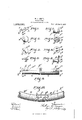
- FIG. 1 is a side elevation of one of the parts.
- FIG. 2 is a side elevation of another part.
- Fig. 3 is a rear end view of Fig. 1.
- Fig. I is an end elevation looking inside Fig. 2.
- Fig. 5 is a front view of Fig. 1.
- Fig. 6 is a front view of Fig. 2.
- Fig. 7 is an elevation of the piece that is fitted in Fig. 2 and also shown in Fig. 4.
- Fig. 8 is a sectional elevation of Fig. 2 showing how the part E in Fig. 7 is held in position.
- Fig. 1 is a side elevation of one of the parts.
- Fig. 2 is a side elevation of another part.
- Fig. 3 is a rear end view of Fig. 1.
- Fig. I is an end elevation looking inside Fig. 2.
- Fig. 5 is a front view of Fig. 1.
- Fig. 6 is a front view of Fig. 2.
- Fig. 10 is a similar View with the parts bent around and shown in position, locked ready for attaching to the rim of the wheel.
- the metal sheath portion is on the inside of the tire that is where the non-extensible material is positio-ned.
- the member 9 is not only nonextensible or non-stretchable, but is also flexible or pliable so that it may be bent in any direction, so that it adapts itself perfectly to the surface of the wheel and may also yield in case the tire is struck a sidelong blow by any inequality in the road surface.
- the female portion B is attached to the nonextensible material in a similar manner to the other end of the tire, the sheath portion also being underneath so as to lie snugly in the channel of the rim of the wheel.
- the tire is then bent around into its circular form, the knob 5 being inserted or pushed through the hole D in the female part until it looks behind the split part E thus looking the two ends together as seen in Fig. 10.
- a vehicle tire comprising in combination, an annulus of solid elastic material, a nonmetallic, flexible, non-stretchable member arranged at the inner surface of said annulus and extending around the entire inner face thereof and attached thereto, said memher and said annulus being divided at one point in the same radial line, and devices for WILLIAM CORBETT SNEYD.
Landscapes
- Engineering & Computer Science (AREA)
- Mechanical Engineering (AREA)
- Tires In General (AREA)
Description
W. C. SNEYD.
VEHICLE TIRE.
APPLICATION FILED 13130.30, 1912.
COLUMBIA FLANDGRAPH co., WASHINGTON, n. c.
WILLIAM GORBETT sNEYD, on SALE, ENGLAND.
VEHICLE TIRE.
Application filed December 30', 1912 To all whom it may concern Be it known that I, IVILLIAM CoRBET'r SNEYD, a subject of the Kingdom of Great Britain, residing at 145a Northenden road, Sale, in the county of Cheshire, England, have invented certain new and useful Improvements in Vehicle-Tires, of which the following is a specification.
Hitherto there has been great difficulty in connecting the ends of solid elastic tires to last any length of time, and the object of my invent-ion is to overcome this difficulty, and for this purpose according to the present invention a solid elastic tire is provided with a non-extensible material which is situated substantially at the inner surface of the tire throughout the whole of its circumference for the purpose of the more convenient attachment of a serrated or other form of clip for locking the two ends of the tire together.
In order that this invention may be clearly understood and readily carried into practice reference may be had to the appended explanatory sheet of drawings upon which Figure l is a side elevation of one of the parts. Fig. 2 is a side elevation of another part. Fig. 3 is a rear end view of Fig. 1. Fig. I is an end elevation looking inside Fig. 2. Fig. 5 is a front view of Fig. 1. Fig. 6 is a front view of Fig. 2. Fig. 7 is an elevation of the piece that is fitted in Fig. 2 and also shown in Fig. 4. Fig. 8 is a sectional elevation of Fig. 2 showing how the part E in Fig. 7 is held in position. Fig. 9 is a piece of rubber showing the two ends with the parts attached to the non-extensible material ready for bending around to be locked. Fig. 10 is a similar View with the parts bent around and shown in position, locked ready for attaching to the rim of the wheel.
In a convenient embodiment of the present invention small pieces of metal A and B are provided as seen in Figs. 1 and 2, these are made with a half cylindrical portion a and Z2 and a disk end a and Z2 the diameter of which will depend upon the size of the tire they are required to fit. Each tire requiring two, one for each end, one of them shown in Fig. 1 being what I should call the male part having a stud like projection C formed on the front of the disk which also has a knob or projection 6 formed on its end,
Specification of Letters-Patent.
Patented Aug. 5,1913. Serial fio. 739,407.
F'g. 2 being what I should call the female part having a hole D into which the stud enters. Inside the female part a small disk E as seen in Fig. 7 is fixed as seen in Fig. 8, this is made of some springy or ductile material and is of a conical shape and split as seen in Fig. 4, so that when the stud C is forced through from the outside it forces open the points F which spring back and lodge behind the knob or projection Z2 The mode of fixing is as follows :-The male part A is fitted on to one end of the tire G and held in position by small rivets or pins f being driven into the non-extensible material 9 there being two of these on one side and one on the other and it will be seen in Figs. 9 and 10 that the metal sheath portion is on the inside of the tire that is where the non-extensible material is positio-ned. As will be clearly apparent from the drawing, the member 9 is not only nonextensible or non-stretchable, but is also flexible or pliable so that it may be bent in any direction, so that it adapts itself perfectly to the surface of the wheel and may also yield in case the tire is struck a sidelong blow by any inequality in the road surface. The female portion B is attached to the nonextensible material in a similar manner to the other end of the tire, the sheath portion also being underneath so as to lie snugly in the channel of the rim of the wheel. The tire is then bent around into its circular form, the knob 5 being inserted or pushed through the hole D in the female part until it looks behind the split part E thus looking the two ends together as seen in Fig. 10.
I am aware that it has been proposed to form tires of a series of circular disks of leather, rubber or the like threaded upon a wire which wire forms an internal core situated in the center of the cross section of the tire, and the ends of which core have been socketed or connected together by an external screw bolt.
that I claim as my invention and desire to secure by Letters Patent is A vehicle tire comprising in combination, an annulus of solid elastic material, a nonmetallic, flexible, non-stretchable member arranged at the inner surface of said annulus and extending around the entire inner face thereof and attached thereto, said memher and said annulus being divided at one point in the same radial line, and devices for WILLIAM CORBETT SNEYD.
Witnesses ANNIE RHODES, ROBERT BILLINGTON.
attaching the extremities of said non-stretchable member together, said devices being provided With means whereby they may be connected one to the other and also disconnected at Will, said non-stretchable member being entirely disconnected from the vehicle rim.
Copies of this patent may be obtained for five cents each, by addressing the Commissioner of Patents, Washington, D. C.
Priority Applications (1)
| Application Number | Priority Date | Filing Date | Title |
|---|---|---|---|
| US73940712A US1069630A (en) | 1912-12-30 | 1912-12-30 | Vehicle-tire. |
Applications Claiming Priority (1)
| Application Number | Priority Date | Filing Date | Title |
|---|---|---|---|
| US73940712A US1069630A (en) | 1912-12-30 | 1912-12-30 | Vehicle-tire. |
Publications (1)
| Publication Number | Publication Date |
|---|---|
| US1069630A true US1069630A (en) | 1913-08-05 |
Family
ID=3137867
Family Applications (1)
| Application Number | Title | Priority Date | Filing Date |
|---|---|---|---|
| US73940712A Expired - Lifetime US1069630A (en) | 1912-12-30 | 1912-12-30 | Vehicle-tire. |
Country Status (1)
| Country | Link |
|---|---|
| US (1) | US1069630A (en) |
-
1912
- 1912-12-30 US US73940712A patent/US1069630A/en not_active Expired - Lifetime
Similar Documents
| Publication | Publication Date | Title |
|---|---|---|
| US2590264A (en) | Sleeve type fastening device for resilient plastic articles and the like | |
| US20140151514A1 (en) | Corrugated tube clamp | |
| US860189A (en) | Cord-adjuster. | |
| US1069630A (en) | Vehicle-tire. | |
| US1246724A (en) | Lacing device. | |
| US1908808A (en) | Tire armor | |
| US662519A (en) | Shoestring-fastener. | |
| US1329126A (en) | Adjustable dust-cap for valve-stems | |
| US423666A (en) | Glove-fastener | |
| US805046A (en) | Spring-tire. | |
| US1062921A (en) | Curtain-fastener for automobiles. | |
| US1278595A (en) | Hub. | |
| US1271609A (en) | Flexible metallic tire for motor and other vehicles. | |
| US907316A (en) | Spring-tire. | |
| US254145A (en) | Vehicle-wheel | |
| US1089859A (en) | Flexible coupling. | |
| US1624035A (en) | Lining for brake bands and shoes | |
| US1326395A (en) | Automobile-tire-chain-repair device. | |
| US1190065A (en) | Pneumatic-tire sleeve or patch. | |
| US2251424A (en) | Tire chain | |
| US1080259A (en) | Antiskidding attachment for tires. | |
| US576772A (en) | Pneumatic bicycle-tire | |
| US1273513A (en) | Stud for snap-fasteners. | |
| US963742A (en) | Spring-wheel. | |
| US1166961A (en) | Vehicle-wheel. |