US10695971B2 - Plastic flooring having registration system - Google Patents
Plastic flooring having registration system Download PDFInfo
- Publication number
- US10695971B2 US10695971B2 US15/871,168 US201815871168A US10695971B2 US 10695971 B2 US10695971 B2 US 10695971B2 US 201815871168 A US201815871168 A US 201815871168A US 10695971 B2 US10695971 B2 US 10695971B2
- Authority
- US
- United States
- Prior art keywords
- roller set
- printing layer
- roller
- sensor
- electronic control
- Prior art date
- Legal status (The legal status is an assumption and is not a legal conclusion. Google has not performed a legal analysis and makes no representation as to the accuracy of the status listed.)
- Active, expires
Links
Images


Classifications
-
- B—PERFORMING OPERATIONS; TRANSPORTING
- B29—WORKING OF PLASTICS; WORKING OF SUBSTANCES IN A PLASTIC STATE IN GENERAL
- B29C—SHAPING OR JOINING OF PLASTICS; SHAPING OF MATERIAL IN A PLASTIC STATE, NOT OTHERWISE PROVIDED FOR; AFTER-TREATMENT OF THE SHAPED PRODUCTS, e.g. REPAIRING
- B29C59/00—Surface shaping of articles, e.g. embossing; Apparatus therefor
- B29C59/02—Surface shaping of articles, e.g. embossing; Apparatus therefor by mechanical means, e.g. pressing
- B29C59/04—Surface shaping of articles, e.g. embossing; Apparatus therefor by mechanical means, e.g. pressing using rollers or endless belts
- B29C59/046—Surface shaping of articles, e.g. embossing; Apparatus therefor by mechanical means, e.g. pressing using rollers or endless belts for layered or coated substantially flat surfaces
-
- B—PERFORMING OPERATIONS; TRANSPORTING
- B29—WORKING OF PLASTICS; WORKING OF SUBSTANCES IN A PLASTIC STATE IN GENERAL
- B29C—SHAPING OR JOINING OF PLASTICS; SHAPING OF MATERIAL IN A PLASTIC STATE, NOT OTHERWISE PROVIDED FOR; AFTER-TREATMENT OF THE SHAPED PRODUCTS, e.g. REPAIRING
- B29C37/00—Component parts, details, accessories or auxiliary operations, not covered by group B29C33/00 or B29C35/00
- B29C37/0025—Applying surface layers, e.g. coatings, decorative layers, printed layers, to articles during shaping, e.g. in-mould printing
-
- B—PERFORMING OPERATIONS; TRANSPORTING
- B32—LAYERED PRODUCTS
- B32B—LAYERED PRODUCTS, i.e. PRODUCTS BUILT-UP OF STRATA OF FLAT OR NON-FLAT, e.g. CELLULAR OR HONEYCOMB, FORM
- B32B37/00—Methods or apparatus for laminating, e.g. by curing or by ultrasonic bonding
- B32B37/0046—Methods or apparatus for laminating, e.g. by curing or by ultrasonic bonding characterised by constructional aspects of the apparatus
- B32B37/0053—Constructional details of laminating machines comprising rollers; Constructional features of the rollers
-
- B—PERFORMING OPERATIONS; TRANSPORTING
- B32—LAYERED PRODUCTS
- B32B—LAYERED PRODUCTS, i.e. PRODUCTS BUILT-UP OF STRATA OF FLAT OR NON-FLAT, e.g. CELLULAR OR HONEYCOMB, FORM
- B32B38/00—Ancillary operations in connection with laminating processes
- B32B38/06—Embossing
-
- B—PERFORMING OPERATIONS; TRANSPORTING
- B32—LAYERED PRODUCTS
- B32B—LAYERED PRODUCTS, i.e. PRODUCTS BUILT-UP OF STRATA OF FLAT OR NON-FLAT, e.g. CELLULAR OR HONEYCOMB, FORM
- B32B38/00—Ancillary operations in connection with laminating processes
- B32B38/14—Printing or colouring
- B32B38/145—Printing
-
- B—PERFORMING OPERATIONS; TRANSPORTING
- B32—LAYERED PRODUCTS
- B32B—LAYERED PRODUCTS, i.e. PRODUCTS BUILT-UP OF STRATA OF FLAT OR NON-FLAT, e.g. CELLULAR OR HONEYCOMB, FORM
- B32B38/00—Ancillary operations in connection with laminating processes
- B32B38/18—Handling of layers or the laminate
- B32B38/1825—Handling of layers or the laminate characterised by the control or constructional features of devices for tensioning, stretching or registration
-
- B—PERFORMING OPERATIONS; TRANSPORTING
- B32—LAYERED PRODUCTS
- B32B—LAYERED PRODUCTS, i.e. PRODUCTS BUILT-UP OF STRATA OF FLAT OR NON-FLAT, e.g. CELLULAR OR HONEYCOMB, FORM
- B32B38/00—Ancillary operations in connection with laminating processes
- B32B38/18—Handling of layers or the laminate
- B32B38/1875—Tensioning
-
- B—PERFORMING OPERATIONS; TRANSPORTING
- B32—LAYERED PRODUCTS
- B32B—LAYERED PRODUCTS, i.e. PRODUCTS BUILT-UP OF STRATA OF FLAT OR NON-FLAT, e.g. CELLULAR OR HONEYCOMB, FORM
- B32B41/00—Arrangements for controlling or monitoring lamination processes; Safety arrangements
-
- B—PERFORMING OPERATIONS; TRANSPORTING
- B29—WORKING OF PLASTICS; WORKING OF SUBSTANCES IN A PLASTIC STATE IN GENERAL
- B29C—SHAPING OR JOINING OF PLASTICS; SHAPING OF MATERIAL IN A PLASTIC STATE, NOT OTHERWISE PROVIDED FOR; AFTER-TREATMENT OF THE SHAPED PRODUCTS, e.g. REPAIRING
- B29C37/00—Component parts, details, accessories or auxiliary operations, not covered by group B29C33/00 or B29C35/00
- B29C2037/90—Measuring, controlling or regulating
- B29C2037/903—Measuring, controlling or regulating by means of a computer
-
- B—PERFORMING OPERATIONS; TRANSPORTING
- B29—WORKING OF PLASTICS; WORKING OF SUBSTANCES IN A PLASTIC STATE IN GENERAL
- B29C—SHAPING OR JOINING OF PLASTICS; SHAPING OF MATERIAL IN A PLASTIC STATE, NOT OTHERWISE PROVIDED FOR; AFTER-TREATMENT OF THE SHAPED PRODUCTS, e.g. REPAIRING
- B29C37/00—Component parts, details, accessories or auxiliary operations, not covered by group B29C33/00 or B29C35/00
- B29C2037/90—Measuring, controlling or regulating
- B29C2037/906—Measuring, controlling or regulating using visualisation means or linked accessories, e.g. screens, printers
-
- B—PERFORMING OPERATIONS; TRANSPORTING
- B29—WORKING OF PLASTICS; WORKING OF SUBSTANCES IN A PLASTIC STATE IN GENERAL
- B29C—SHAPING OR JOINING OF PLASTICS; SHAPING OF MATERIAL IN A PLASTIC STATE, NOT OTHERWISE PROVIDED FOR; AFTER-TREATMENT OF THE SHAPED PRODUCTS, e.g. REPAIRING
- B29C2795/00—Printing on articles made from plastics or substances in a plastic state
- B29C2795/007—Printing on articles made from plastics or substances in a plastic state after shaping
-
- B—PERFORMING OPERATIONS; TRANSPORTING
- B32—LAYERED PRODUCTS
- B32B—LAYERED PRODUCTS, i.e. PRODUCTS BUILT-UP OF STRATA OF FLAT OR NON-FLAT, e.g. CELLULAR OR HONEYCOMB, FORM
- B32B2419/00—Buildings or parts thereof
- B32B2419/04—Tiles for floors or walls
Definitions
- the present invention relates to plastic flooring having a registration system.
- a conventional registration device contains: two electromagnetic discs 61 , 62 fixed on two ends of a first roller 1 on a slidable plate 63 , a first sensing wire 65 and a second sensing wire 66 which are printed on two sides of a surface skin 2 of the first roller 1 , and a sensing device 5 .
- the sensing device 5 includes a first electric eye 64 and a second electric eye 67 .
- a second roller 4 includes a third sensing wire 71 correspond to the second sensing wire 66 of the first roller 1 , detection points 72 arranged on one end thereof correspond to the third sensing wire 71 , and electric detecting eyes 73 .
- the sensing device 5 and the electric detecting eyes 73 receive signals and inputs the signal into a computer so that an adjustment unit 60 calculates offset so as to drive a motor 130 to rotate clockwise and counterclockwise, hence the slidable plate 63 move horizontally, and computing units 80 and 70 process the signals and send the signals to the computer 90 .
- the computer controls the two electromagnetic discs 61 , 62 to adjust rotation speed of the first roller 1 so that the surface skin 2 and the second roller 4 rolls and produce patterns of plastic floor tiles.
- the conventional registration device is complicated and cannot adjust an error between the surface skin 2 and the second roller 4 accurately.
- a CCD sensor 91 senses color code and node on a printing layer 92 , but errors of the color code and the node cannot be judged exactly.
- a controller starts a heater 90 to heat the printing layer 92 so as to deliver the printing layer 92 quickly.
- errors between the printing layer and the second roller 4 cannot be adjusted accurately.
- the present invention has arisen to mitigate and/or obviate the afore-described disadvantages.
- the primary aspect of the present invention is to provide plastic flooring having a registration system in which the computing module receives sensed values of the first sensors and the second sensor and compares the divided number so as to judge the error between the pressing patterns of the fourth roller set and the surface patterns of the printing layer, thereafter, the tension regulator and the fourth roller set adjust the error so as to position the three-dimensional patterns accurately at a low cost.
- plastic flooring provided by the present invention contains: an electronic control unit electrically connected with roller equipment and the registration system, the roller equipment being configured to deliver a substrate, a printing layer, and an abrasion resistance layer toward a rolling device so that the rolling device rolls the plastic flooring, the rolling device including a fourth roller set having pressing patterns identical to surface patterns of the printing layer, and the registration system having a first sensor, a tension regulator, and a second sensor.
- the first sensor is disposed on a delivery path of the printing layer, the printing layer corresponds to the first sensor, the printing layer has multiple positioning points separated from one another, wherein a length between a first positioning point and a second positioning point depends on a perimeter of the fourth roller set so as to form a print unit, and the first sensor is configured to sense the multiple positioning points and to transmit sensed signals to the electronic control unit.
- the tension regulator is mounted on a delivery start end of the printing layer so as to adjust tension as delivering the printing layer.
- the second sensor is configured to sense rotation location of the fourth roller set, and a perimeter of the fourth roller set is equal to a length of the print unit of the printing layer, wherein the fourth roller set has at least one first start point formed thereon so that the second sensor sends sensed signal of the at least one first start point to the electronic control.
- the electronic control unit includes a computing module, when receiving sensed signals of each positioning point of the printing layer, the computing module divides the print unit into several parts evenly and constructs successive delivery simulation of a travel and a transportation speed from a delivery starting point to the fourth roller set; when the electronic control unit receives signals of the at least one first start point of the fourth roller set, the computing module simulates a divided number of the perimeter of the fourth roller set, and the divided number of the perimeter of the fourth roller set is identical to a simulating number of the print unit so as to compare simulated data of the printing layer and that of the fourth roller set, hence when the base, the printing layer, and the abrasion resistance layer are rolled by the fourth roller set, it is possible to judge whether the pressing patterns correspond to the surface patterns of the printing layer.
- the tension regulator adjusts the tension of the printing layer so as to regulate an error between the pressing patterns of the fourth roller set and the surface patterns of the printing layer.
- FIG. 1 is a schematic view showing the operation of plastic flooring having registration system according to a preferred embodiment of the present invention.
- FIG. 2 is a schematic view showing the operation of plastic flooring having registration system according to another preferred embodiment of the present invention.
- FIG. 3 is a schematic view showing the operation of plastic flooring having registration system according to another preferred embodiment of the present invention.
- FIG. 4 is a schematic view showing the operation of a part of plastic flooring having registration system according to the preferred embodiment of the present invention.
- FIG. 5 is another schematic view showing the operation of a part of plastic flooring having registration system according to the preferred embodiment of the present invention.
- FIG. 6 is also another schematic view showing the operation of a part of plastic flooring having registration system according to the preferred embodiment of the present invention.
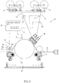
- FIG. 7 is still another schematic view showing the operation of a part of plastic flooring having registration system according to the preferred embodiment of the present invention.
- FIG. 8 is a perspective view of a conventional registration device.
- FIG. 9 is a schematic view of another conventional registration device.
- plastic flooring having registration system comprises: a substrate 11 , a printing layer 12 , an abrasion resistance layer 13 , and roller equipment 20 having a rolling device 30 configured to deliver and roll the substrate 11 , the printing layer 12 , and the abrasion resistance layer 13 so that the rolling equipment 20 rolls the substrate 11 , the printing layer 12 , and the abrasion resistance layer 13 together by mating with a registration system 20 and an electronic control unit 50 , thus forming three-dimensional patterns on the plastic flooring.
- the roller equipment 20 further includes a first delivery roller 21 configured to deliver the printing layer 12 toward the rolling device 30 , a second delivery roller 22 configured to convey the abrasion resistance layer 13 toward the rolling device 30 , and a feeding roller 23 configured to facilitate delivery stability toward the abrasion resistance layer 13 .
- the registration transferring system 30 includes four roller sets horizontally arranged therein, for example, the registration transferring system 30 includes a first roller set 31 fixed on a machine frame configured to roll the substrate 11 in a predetermined thickness, a second roller 32 configured to roll the printing layer 12 onto the roller 11 , a third roller set 33 configured to roll the abrasion resistance layer 13 onto the printing layer 12 , and a fourth roller set 34 configured to roll the substrate 11 , the printing layer 12 , and the abrasion resistance layer 13 .
- the registration transferring system includes five roller sets horizontally arranged therein, for example, the registration transferring system 30 includes the first roller set 31 , a fifth roller set 35 , and the fourth roller set 34 , wherein the printing layer 11 and the abrasion resistance layer 13 are guided toward the fifth roller set 35 by way of a guiding roller set 36 so that the printing layer 11 and the abrasion resistance layer 13 are rolled by the fifth roller set 35 .
- the registration transferring system 30 includes fourth roller sets vertically arranged therein, for example, the registration transferring system 30 includes two transportation rollers 37 , a mirror roller 38 , and a fourth roller set 34 which are arranged from a lower end of the machine frame to an upper end of the machine frame.
- the fourth roller set 34 has pressing patterns 341 formed thereon identical to surface patterns of the printing layer 12 so as to roll the base 11 , the printing layer 12 , and the abrasion resistance layer 13 , thus forming the three-dimensional patterns on the plastic flooring.
- the registration system 40 includes a first sensor 41 , a second sensor 42 , and a tension regulator 43 .
- the first sensor 41 is an electric eye or a camera and is disposed on a starting portion of a delivery path of the printing layer 12 , wherein the printing layer 12 corresponds to a profile of the first sensor 41 , the printing layer 12 has multiple positioning points 121 separated from one another, wherein a length between a first positioning point 121 and a second positioning point 121 ′ depends on a perimeter of the fourth roller set 34 so as to form a print unit 122 , and the perimeter of the fourth roller set 34 is more than a length of the print unit 12 .
- the first sensor 41 is configured to sense the multiple positioning points 121 and transmits sensed signals to the electronic control unit 50 .
- the second sensor 42 is configured to sense rotation angle and location of the fourth roller set 34 , wherein the fourth roller set 34 has at least one first start point 342 formed thereon so that the second sensor 42 sends sensed signal of the at least one first start point 342 to the electronic control unit 50 .
- the at least one first start point 342 is formed on two outer surfaces of the fourth roller set 34 .
- a rotating disc 391 is rotatably connected on a rotary shaft of the fourth roller set 34 and the at least one first start point 342 is formed on the rotating disc 391 , wherein the at least one first start point 342 is a signal receiving element, and the second sensor 42 transmits light signals.
- the fourth roller set 34 rotates, the light signals contact with the at least one first start point 342 from the second sensor 42 so as to send the sensed signals toward the electronic control unit 50 .
- the at least one first start point 342 is formed on an encoder 392 , and the encoder 392 is fixed on the rotary shaft of the fourth roller set 34 , wherein the second sensor 42 mates with the encoder 392 so as to sense an original position of the fourth roller set 34 or/and the rotation angle of the fourth roller set 34 , and the second sensor 42 transmits the sensed signals to the electronic control unit 50 .
- the tension regulator 43 is mounted on a delivery start end of the printing layer 12 so as to adjust tension as delivering the printing layer 12 .
- the electronic control unit 50 is electrically connected with the roller equipment 20 , the rolling device 30 , and the registration system 40 , wherein the electronic control unit 50 includes a computing module 51 , when receiving the sensed signals of each positioning point 121 of the printing layer 12 , the computing module 51 divides the print unit 122 into several parts evenly and constructs successive delivery simulation of a travel and a transportation speed from a delivery starting point to the fourth roller set 34 .
- the computing module 51 simulates a divided number of the perimeter of the fourth roller set 34 , and the divided number of the perimeter of the fourth roller set 34 is identical to a simulating number of the print unit 122 so as to compare simulated data of the printing layer 12 and that of the fourth roller set 34 , hence when the base 11 , the printing layer 12 , and the abrasion resistance layer 13 are rolled by the fourth roller set 34 , it is possible to judge whether the pressing patterns 341 correspond to the surface patterns of the printing layer 12 .
- the tension regulator 43 adjusts the tension of the printing layer 12 so as to regulate an error between the pressing patterns 341 of the fourth roller set 34 and the surface patterns of the printing layer 12 .
- a judged value of the error is accurate more and more.
- a rotation speed of the fourth roller set 34 is adjusted by mating a third sensor 44 or a fourth sensor 45 with a locating roller 39 so as to adjust the error between the pressing patterns 341 of the fourth roller set 34 and the surface patterns of the printing layer 12 .
- the tension regulator 43 adjusts the tension of the printing layer 12
- the rotation speed of the fourth roller set 34 is adjustable.
- the locating roller 39 is arranged adjacent to the fourth roller set 34 and its diameter is equal to that of the fourth roller set 34 , and the perimeter of the locating roller 39 is identical to the length of the print unit 12 , and the locating roller 39 has a second start point 391 formed on one side thereof and a third sensor 44 fixed outside the second start point 391 so that the third sensor 44 senses rotation of the locating roller 39 and transmits sensed information of the second start point 39 to the electronic control unit 50 .
- the computing module 51 simulates a divided number of a perimeter of the locating roller 39 identical to that of the print unit 122 , hence before the fourth roller set 34 rolls the printing layer 12 , the simulated data of the printing layer 12 is compared with that of the locating roller 39 so as to judge whether the pressing patterns 341 of the fourth roller set 34 correspond to the surface patterns of the printing layer 12 .
- the tension regulator 43 adjusts the tension of the printing layer 12 .
- the rotation speed of the fourth roller set 34 is adjusted so as to regulate the error between the pressing patterns 341 of the fourth roller set 34 and the surface patterns of the printing layer 12 .
- the roller equipment 20 includes the fifth roller set 35 configured to roll the substrate 11 , the printing layer 12 , and the abrasion resistance layer 13
- the fourth sensor 45 is arranged adjacent to the fifth roller set 35 , wherein after the substrate 11 , the printing layer 12 , and the abrasion resistance layer 13 are rolled, and the fourth sensor 45 senses the multiple positioning points 121 and transmits the sensed signals to the electronic control unit 50 .
- the computing module 51 compares whether a delivery travel of the printing layer 12 from the first sensor 41 to the second sensor 42 is equal to a delivery simulation travel of the computing module 51 , thus judging whether the surface patterns of the printing layer 12 correspond to the pressing patterns 341 of the fourth roller set 34 .
- the tension regulator 43 adjusts the tension of the printing layer 12 .
- the rotation speed of the fourth roller set 34 is adjusted so as to regulate the error between the pressing patterns 341 of the fourth roller set 34 and the surface patterns of the printing layer 12 .
- the computing module 51 receives sensed values of the first sensors 41 and the second sensor 42 and compares the divided number so as to judge the error between the pressing patterns 341 of the fourth roller set 34 and the surface patterns of the printing layer 12 . Thereafter, the tension regulator 43 and the fourth roller set 34 adjust the error so as to position the three-dimensional patterns accurately at a low cost.
Landscapes
- Engineering & Computer Science (AREA)
- Mechanical Engineering (AREA)
- Printing Methods (AREA)
- Force Measurement Appropriate To Specific Purposes (AREA)
Abstract
Description
Claims (6)
Priority Applications (1)
| Application Number | Priority Date | Filing Date | Title |
|---|---|---|---|
| US15/871,168 US10695971B2 (en) | 2018-01-15 | 2018-01-15 | Plastic flooring having registration system |
Applications Claiming Priority (1)
| Application Number | Priority Date | Filing Date | Title |
|---|---|---|---|
| US15/871,168 US10695971B2 (en) | 2018-01-15 | 2018-01-15 | Plastic flooring having registration system |
Publications (2)
| Publication Number | Publication Date |
|---|---|
| US20190217524A1 US20190217524A1 (en) | 2019-07-18 |
| US10695971B2 true US10695971B2 (en) | 2020-06-30 |
Family
ID=67212613
Family Applications (1)
| Application Number | Title | Priority Date | Filing Date |
|---|---|---|---|
| US15/871,168 Active 2038-04-27 US10695971B2 (en) | 2018-01-15 | 2018-01-15 | Plastic flooring having registration system |
Country Status (1)
| Country | Link |
|---|---|
| US (1) | US10695971B2 (en) |
Families Citing this family (3)
| Publication number | Priority date | Publication date | Assignee | Title |
|---|---|---|---|---|
| EP3708367B1 (en) * | 2019-03-13 | 2022-05-11 | Ding Yi Lu | Equipment for making plastic flooring |
| CN116368016A (en) | 2020-10-19 | 2023-06-30 | 爱克发有限公司 | Method of manufacturing decorative panels |
| PL4261046T3 (en) | 2022-04-12 | 2025-02-24 | Akzenta Paneele + Profile Gmbh | Method of manufacturing a decorative panel with improved synchronization of the decorative motif and structure |
Citations (7)
| Publication number | Priority date | Publication date | Assignee | Title |
|---|---|---|---|---|
| US4225374A (en) * | 1978-04-20 | 1980-09-30 | Armstrong Cork Company | Decorative flooring |
| US5304272A (en) * | 1991-08-12 | 1994-04-19 | American Biltrite, Inc. | Method for manufacture of process printed surface covering |
| US6416607B1 (en) * | 1999-10-07 | 2002-07-09 | Industrial Technology Research Institute | Automatic embossing device for plastic floor tile |
| US20130276965A1 (en) * | 2010-10-11 | 2013-10-24 | Jin Hyung Kim | Decorative stainless steel rolled sheet with embossed patterns and method of manufacturing the same |
| US20150165748A1 (en) * | 2013-12-16 | 2015-06-18 | Armstrong World Industries, Inc. | Continuous floor product forming system and process |
| US9296146B1 (en) * | 2012-03-09 | 2016-03-29 | Rambus Delaware Llc | Extrusion-to-sheet production line and method |
| US20170361522A1 (en) * | 2016-06-15 | 2017-12-21 | Caiqin ZHU | Long decorative material with embossing in register with pattern and rolling method and device therefor |
-
2018
- 2018-01-15 US US15/871,168 patent/US10695971B2/en active Active
Patent Citations (7)
| Publication number | Priority date | Publication date | Assignee | Title |
|---|---|---|---|---|
| US4225374A (en) * | 1978-04-20 | 1980-09-30 | Armstrong Cork Company | Decorative flooring |
| US5304272A (en) * | 1991-08-12 | 1994-04-19 | American Biltrite, Inc. | Method for manufacture of process printed surface covering |
| US6416607B1 (en) * | 1999-10-07 | 2002-07-09 | Industrial Technology Research Institute | Automatic embossing device for plastic floor tile |
| US20130276965A1 (en) * | 2010-10-11 | 2013-10-24 | Jin Hyung Kim | Decorative stainless steel rolled sheet with embossed patterns and method of manufacturing the same |
| US9296146B1 (en) * | 2012-03-09 | 2016-03-29 | Rambus Delaware Llc | Extrusion-to-sheet production line and method |
| US20150165748A1 (en) * | 2013-12-16 | 2015-06-18 | Armstrong World Industries, Inc. | Continuous floor product forming system and process |
| US20170361522A1 (en) * | 2016-06-15 | 2017-12-21 | Caiqin ZHU | Long decorative material with embossing in register with pattern and rolling method and device therefor |
Also Published As
| Publication number | Publication date |
|---|---|
| US20190217524A1 (en) | 2019-07-18 |
Similar Documents
| Publication | Publication Date | Title |
|---|---|---|
| US10695971B2 (en) | Plastic flooring having registration system | |
| US20190210388A1 (en) | Apparatus for registered foil stamping and a process therefor | |
| JP4112709B2 (en) | Buckle plate folding station and control method thereof | |
| CN106715133A (en) | Process for producing a surface covering with an embossed printed surface | |
| CN103792809B (en) | Image forming apparatus | |
| US20180281472A1 (en) | Conveyor belt sensors | |
| CN209888141U (en) | Pattern-matching adjusting device for plastic floor | |
| CN109940867A (en) | The synchronization registering unit of improved plastic floor | |
| US10940704B2 (en) | Conveyor belt sensors | |
| JP2619148B2 (en) | Method and apparatus for applying a pattern to a metal coil | |
| US7694965B2 (en) | Feeder speed | |
| EP3308952B1 (en) | Plastic flooring having registration patterns | |
| US20130068814A1 (en) | Web conveying device, printing apparatus, and tension control method | |
| CN103660624A (en) | Conveyance apparatus and recording apparatus, and control method thereof | |
| EP3708367A1 (en) | Plastic flooring having registration system | |
| US8358438B2 (en) | Apparatuses and methods for automatic printing press optimization | |
| US10723114B1 (en) | Device of adjusting registration of plastic flooring | |
| US10384427B2 (en) | Plastic flooring having registration patterns | |
| EP3708366B1 (en) | Device of adjusting registration of plastic flooring | |
| KR20130055172A (en) | Substrate aligning unit, substrate processing apparatus having the same and method of processing substrate using the same | |
| JP2781267B2 (en) | Cylindrical transfer printing method and apparatus | |
| KR101689027B1 (en) | Cover printer of book type printed matter | |
| CN111516252B (en) | Adjustment device for plastic floor | |
| CN113524647A (en) | Synchronous register system for second-generation plastic floor | |
| JPH1191080A (en) | Method and apparatus for positioning remote regulable element in printer |
Legal Events
| Date | Code | Title | Description |
|---|---|---|---|
| FEPP | Fee payment procedure |
Free format text: ENTITY STATUS SET TO UNDISCOUNTED (ORIGINAL EVENT CODE: BIG.); ENTITY STATUS OF PATENT OWNER: MICROENTITY |
|
| FEPP | Fee payment procedure |
Free format text: ENTITY STATUS SET TO MICRO (ORIGINAL EVENT CODE: MICR); ENTITY STATUS OF PATENT OWNER: MICROENTITY |
|
| STPP | Information on status: patent application and granting procedure in general |
Free format text: NON FINAL ACTION MAILED |
|
| STPP | Information on status: patent application and granting procedure in general |
Free format text: RESPONSE TO NON-FINAL OFFICE ACTION ENTERED AND FORWARDED TO EXAMINER |
|
| STPP | Information on status: patent application and granting procedure in general |
Free format text: NOTICE OF ALLOWANCE MAILED -- APPLICATION RECEIVED IN OFFICE OF PUBLICATIONS |
|
| STCF | Information on status: patent grant |
Free format text: PATENTED CASE |
|
| AS | Assignment |
Owner name: LIU, DING YI, CHINA Free format text: ASSIGNMENT OF ASSIGNORS INTEREST;ASSIGNOR:LIOU, TING YI;REEL/FRAME:058160/0121 Effective date: 20211116 Owner name: CHAO, PEI DONG, TAIWAN Free format text: ASSIGNMENT OF ASSIGNORS INTEREST;ASSIGNOR:LIOU, TING YI;REEL/FRAME:058160/0121 Effective date: 20211116 |
|
| AS | Assignment |
Owner name: YI, LU DING, CHINA Free format text: ASSIGNMENT OF ASSIGNORS INTEREST;ASSIGNOR:LIU, DING YI;REEL/FRAME:059693/0662 Effective date: 20220420 |
|
| MAFP | Maintenance fee payment |
Free format text: PAYMENT OF MAINTENANCE FEE, 4TH YEAR, MICRO ENTITY (ORIGINAL EVENT CODE: M3551); ENTITY STATUS OF PATENT OWNER: MICROENTITY Year of fee payment: 4 |
|
| AS | Assignment |
Owner name: WUXI BOYU PLASTIC MACHINERY CO., LTD., CHINA Free format text: ASSIGNMENT OF ASSIGNORS INTEREST;ASSIGNORS:YI, LU DING;CHAO, PEI DONG;REEL/FRAME:067906/0423 Effective date: 20240513 |