US10695843B2 - System for machining of a component, and component and clamping element for the system - Google Patents
System for machining of a component, and component and clamping element for the system Download PDFInfo
- Publication number
- US10695843B2 US10695843B2 US15/636,796 US201715636796A US10695843B2 US 10695843 B2 US10695843 B2 US 10695843B2 US 201715636796 A US201715636796 A US 201715636796A US 10695843 B2 US10695843 B2 US 10695843B2
- Authority
- US
- United States
- Prior art keywords
- clamping
- auxiliary structure
- component
- adapter
- base body
- Prior art date
- Legal status (The legal status is an assumption and is not a legal conclusion. Google has not performed a legal analysis and makes no representation as to the accuracy of the status listed.)
- Active, expires
Links
Images


Classifications
-
- B—PERFORMING OPERATIONS; TRANSPORTING
- B23—MACHINE TOOLS; METAL-WORKING NOT OTHERWISE PROVIDED FOR
- B23B—TURNING; BORING
- B23B31/00—Chucks; Expansion mandrels; Adaptations thereof for remote control
- B23B31/02—Chucks
- B23B31/10—Chucks characterised by the retaining or gripping devices or their immediate operating means
- B23B31/117—Retention by friction only, e.g. using springs, resilient sleeves, tapers
-
- B—PERFORMING OPERATIONS; TRANSPORTING
- B23—MACHINE TOOLS; METAL-WORKING NOT OTHERWISE PROVIDED FOR
- B23Q—DETAILS, COMPONENTS, OR ACCESSORIES FOR MACHINE TOOLS, e.g. ARRANGEMENTS FOR COPYING OR CONTROLLING; MACHINE TOOLS IN GENERAL CHARACTERISED BY THE CONSTRUCTION OF PARTICULAR DETAILS OR COMPONENTS; COMBINATIONS OR ASSOCIATIONS OF METAL-WORKING MACHINES, NOT DIRECTED TO A PARTICULAR RESULT
- B23Q3/00—Devices holding, supporting, or positioning work or tools, of a kind normally removable from the machine
- B23Q3/02—Devices holding, supporting, or positioning work or tools, of a kind normally removable from the machine for mounting on a work-table, tool-slide, or analogous part
- B23Q3/10—Auxiliary devices, e.g. bolsters, extension members
-
- B—PERFORMING OPERATIONS; TRANSPORTING
- B23—MACHINE TOOLS; METAL-WORKING NOT OTHERWISE PROVIDED FOR
- B23B—TURNING; BORING
- B23B31/00—Chucks; Expansion mandrels; Adaptations thereof for remote control
- B23B31/02—Chucks
- B23B31/10—Chucks characterised by the retaining or gripping devices or their immediate operating means
- B23B31/102—Jaws, accessories or adjustment means
-
- B—PERFORMING OPERATIONS; TRANSPORTING
- B23—MACHINE TOOLS; METAL-WORKING NOT OTHERWISE PROVIDED FOR
- B23B—TURNING; BORING
- B23B31/00—Chucks; Expansion mandrels; Adaptations thereof for remote control
- B23B31/02—Chucks
- B23B31/10—Chucks characterised by the retaining or gripping devices or their immediate operating means
- B23B31/12—Chucks with simultaneously-acting jaws, whether or not also individually adjustable
- B23B31/16—Chucks with simultaneously-acting jaws, whether or not also individually adjustable moving radially
- B23B31/1627—Details of the jaws
-
- B—PERFORMING OPERATIONS; TRANSPORTING
- B23—MACHINE TOOLS; METAL-WORKING NOT OTHERWISE PROVIDED FOR
- B23Q—DETAILS, COMPONENTS, OR ACCESSORIES FOR MACHINE TOOLS, e.g. ARRANGEMENTS FOR COPYING OR CONTROLLING; MACHINE TOOLS IN GENERAL CHARACTERISED BY THE CONSTRUCTION OF PARTICULAR DETAILS OR COMPONENTS; COMBINATIONS OR ASSOCIATIONS OF METAL-WORKING MACHINES, NOT DIRECTED TO A PARTICULAR RESULT
- B23Q3/00—Devices holding, supporting, or positioning work or tools, of a kind normally removable from the machine
- B23Q3/02—Devices holding, supporting, or positioning work or tools, of a kind normally removable from the machine for mounting on a work-table, tool-slide, or analogous part
- B23Q3/06—Work-clamping means
- B23Q3/062—Work-clamping means adapted for holding workpieces having a special form or being made from a special material
- B23Q3/065—Work-clamping means adapted for holding workpieces having a special form or being made from a special material for holding workpieces being specially deformable, e.g. made from thin-walled or elastic material
-
- B—PERFORMING OPERATIONS; TRANSPORTING
- B23—MACHINE TOOLS; METAL-WORKING NOT OTHERWISE PROVIDED FOR
- B23B—TURNING; BORING
- B23B2226/00—Materials of tools or workpieces not comprising a metal
- B23B2226/61—Plastics not otherwise provided for, e.g. nylon
-
- B—PERFORMING OPERATIONS; TRANSPORTING
- B23—MACHINE TOOLS; METAL-WORKING NOT OTHERWISE PROVIDED FOR
- B23Q—DETAILS, COMPONENTS, OR ACCESSORIES FOR MACHINE TOOLS, e.g. ARRANGEMENTS FOR COPYING OR CONTROLLING; MACHINE TOOLS IN GENERAL CHARACTERISED BY THE CONSTRUCTION OF PARTICULAR DETAILS OR COMPONENTS; COMBINATIONS OR ASSOCIATIONS OF METAL-WORKING MACHINES, NOT DIRECTED TO A PARTICULAR RESULT
- B23Q2703/00—Work clamping
- B23Q2703/02—Work clamping means
- B23Q2703/10—Devices for clamping workpieces of a particular form or made from a particular material
-
- B—PERFORMING OPERATIONS; TRANSPORTING
- B23—MACHINE TOOLS; METAL-WORKING NOT OTHERWISE PROVIDED FOR
- B23Q—DETAILS, COMPONENTS, OR ACCESSORIES FOR MACHINE TOOLS, e.g. ARRANGEMENTS FOR COPYING OR CONTROLLING; MACHINE TOOLS IN GENERAL CHARACTERISED BY THE CONSTRUCTION OF PARTICULAR DETAILS OR COMPONENTS; COMBINATIONS OR ASSOCIATIONS OF METAL-WORKING MACHINES, NOT DIRECTED TO A PARTICULAR RESULT
- B23Q2703/00—Work clamping
- B23Q2703/12—Accessories for attaching
Definitions
- Exemplary embodiments relate to a system for machining a component and to the component and a clamping element for the system.
- components are clamped in a clamping chuck, for example, with the help of clamping jaws.
- An axial securing of the component usually occurs here by friction fit.
- One such application is, for example, the turning of plastic or plastic semi-finished products.
- the semi-finished product or the plastic component that is to be turned is fixed in a jaw chuck by clamping jaws.
- the semi-finished product or the to-be-processed component is then held only by friction between a semi-finished product outer side and a clamping jaw contour. High clamping forces are thus required.
- Under unfavorable circumstances it can happen that the semi-finished product or the to-be-processed component is deformed.
- a high number of clamping-jaw sets for example, more than 15, possibly even 18, are usually used.
- Each set here is matched to a certain diameter range. Almost the entire circumference of the semi-finished product can thereby be enclosed by the matching set. Providing so many different clamping jaw sets can possibly be very material- and space-intensive.
- Exemplary embodiments relate to a system for machining a component.
- the system comprises the component including a base body made of plastic.
- the component also comprises a clamping auxiliary structure.
- the system comprises a clamping element that is configured to clamp the component.
- the clamping element comprises at least one clamping jaw including at least one counter-clamping auxiliary structure.
- the counter-clamping auxiliary structure is configured to engage the clamping auxiliary structure and fix the component by interference fit in the axial direction with respect to the clamping element. Since an interference fit is present in the axial direction, in some exemplary embodiments a lower number of clamping jaws and/or a lower clamping force can be used as compared to variants wherein the axial securing is achieved via a friction fit. In some exemplary embodiments a deforming of the component can thereby be at least reduced or even completely prevented.
- the component can be all possible components that come into consideration for a machining, for example, a turning, a grinding, or the like, for example, a semi-finished product, a tube, for example, having an annular cross-section, a cylinder, for example, having a circular, a rectangular, a triangular, or another cross-section, a cone, or the like. Additionally or alternatively the base body can also have one of the described shapes.
- plastics can be used as plastic, for example, polyethylene (PE), HDPE (high-density PE), LLDPE (linear low-density PE), LDPE (low density PE), polypropylene (PP), polyvinyl chloride (PVC), polystyrene (PS), polyurethane (PU/PUR), polyethylene terephthalate (PET), or the like.
- PE polyethylene
- HDPE high-density PE
- LLDPE linear low-density PE
- LDPE low density PE
- PP polypropylene
- PVC polyvinyl chloride
- PS polystyrene
- PUR polyurethane
- PET polyethylene terephthalate
- the clamping element can be, for example, any component that is configured to hold a component for a machining, for example, for a turning.
- the clamping element can be configured to arrange the component such that it can be rotated about its own longitudinal or rotational axis.
- the clamping element can include at least one clamping jaw, but also two or three clamping jaws.
- the clamping auxiliary structure and the counter-clamping auxiliary structure which are in engagement with each other in order to fix the component in the axial direction in an interference-fit manner and via a clamping element, can be any structures on the component and the clamping jaw that in combination with each other make possible an interference fit in the axial direction.
- the clamping auxiliary structure can be a recess
- the counter-clamping auxiliary structure can be projection, a hook, or an elevation that engages in the recess.
- a fixing in the axial direction can then be present, for example, when a relative moving of the component with respect to the clamping element is prevented in the axial direction.
- the component can also be fixed in the circumferential direction and/or in the radial direction in the clamping element, for example, in a friction- or interference-fit manner.
- the clamping auxiliary structure can have a larger diameter and/or a smaller diameter than a surface of the component, which surface is directly adjacent in the axial direction.
- the interference fit with the counter-clamping auxiliary structure can thus be achieved in a simple manner.
- the counter-clamping auxiliary structure can be configured as a male counter-piece corresponding to a female clamping auxiliary structure.
- the counter-clamping auxiliary structure can also be configured as a female counter-piece corresponding to a male clamping auxiliary structure.
- the clamping auxiliary structure can be a groove or notch, which groove or notch is completely encircling in the circumferential direction.
- the recess can have any cross-sectional shape, for example, rectangular, triangular, square, round, or oval.
- the counter-clamping auxiliary structure can have an identical or similar cross-section. Under certain circumstances the counter-clamping auxiliary structure can have a smaller extension in the axial direction than the clamping auxiliary structure if the clamping auxiliary structure has the elevation. Alternatively the clamping auxiliary structure can also have a smaller extension in the axial direction than the counter-clamping auxiliary structure if the clamping auxiliary structure has the elevation with respect to the surrounding surface.
- the clamping auxiliary structure can include at least one stop in the axial direction or even two stops in the axial direction.
- the counter-clamping auxiliary structure can include exactly one or at least one stop in the axial direction or even two such stops.
- the counter-clamping auxiliary structure can be disposed, for example, on a radially inwardly directed surface of the clamping jaw.
- a clamping surface of the clamping jaw which clamping surface is in contact with the component, is directed radially inward
- an interference fit can thus be achieved in the axial direction.
- the counter-clamping auxiliary structure can extend completely along an extension of the clamping surface of the clamping jaw.
- the counter-clamping auxiliary structure can have a smaller extension in the circumferential direction than the clamping jaw or its radially inwardly directed surface, for example, at most 10%, 20%, 30%, 40%, 50%, 60%, 70%, 80%, or 90%.
- the counter-clamping auxiliary structure can be disposed on an edge of the clamping surface, for example, on an edge facing away from the clamping chuck or on an edge facing the clamping chuck.
- the clamping auxiliary structure can also be disposed spaced from the edges of the clamping jaw.
- the component can also be configured such that its radially inwardly directed surface is in contact with at least one radially outwardly directed clamping surface of a clamping jaw of a clamping element.
- the clamping auxiliary structure can be disposed in the circumferential direction at least overlapping with respect to the at least one clamping jaw. In some exemplary embodiments it can thereby be made possible that the at least one clamping jaw that includes the counter-clamping auxiliary structure can enter into engagement with the clamping auxiliary structure.
- the clamping auxiliary structure may be disposed only in a region that overlaps with the clamping jaw in the circumferential direction.
- the clamping auxiliary structure that is disposed overlapping with respect to a clamping jaw can have an extension the same as the clamping jaw in the circumferential direction or greater than the clamping jaw in the circumferential direction by more than 5%, 10%, or 20%.
- clamping auxiliary structure can be arranged completely encircling in the circumferential direction.
- an arranging of the clamping jaws or of the clamping chuck can thereby be simplified.
- the clamping element can include exactly three clamping jaws. In some exemplary embodiments a geometrically determined fixing of the component in the clamping element can thereby be made possible.
- the three clamping jaws can each be arranged, for example, in an angular spacing of 120°. Additionally or alternatively the three clamping jaws can be disposed at the same axial height. In some exemplary embodiments the clamping element can also include a higher number of clamping jaws, for example, at most four, five, six, seven, eight, or ten.
- the base body can be a cylinder, a hollow cylinder, for example, a circular cylinder, a circular hollow cylinder, a cone, for example, a circular cone, a circular hollow cone, or a truncated cone.
- the component is already close to the shape of a final product that is to be manufactured by turning.
- the product can be all possible end products, for example, a seal, an O-ring, a bearing bush, a spacer, or the like.
- the component can comprise an adapter.
- the adapter can be connected, for example, to the base body and have a larger diameter than the base body.
- the clamping auxiliary structure can, for example, be disposed on the adapter. In some exemplary embodiments even components having a smaller outer diameter can thereby be clamped by the clamping element.
- the adapter can be, for example, an annular component.
- An inner diameter of the adapter can be, for example, identical or similar to an outer diameter of the base body. Under certain circumstances the adapter can include a different material than the base body.
- the adapter and the base body can possibly be welded to each other.
- the clamping auxiliary structure can be disposed, for example, overlapping in the axial direction with respect to the adapter.
- the adapter can comprise the clamping auxiliary structure.
- the clamping auxiliary structure can be disposed close to an end edge of the adapter, for example, on an end edge that is facing away from the clamping element in a clamped state.
- the clamping auxiliary structure can be spaced from the end edge, for example, at most by 10%, 5%, 2%, 3%, or 1% of an axial extension of the adapter.
- the adapter can, for example, be disposed overlapping in an axial direction with respect to the base body.
- An axial extension of the adapter can correspond to at most 20%, 10%, 5%, or 2% of an axial extension of the base body and/or at least 1%, 2%, 3%, 4%, or 5% of an axial extension of the base body.
- clamping auxiliary structure can also be disposed directly on the base body. This can be the case, for example, in exemplary embodiments wherein the component includes no adapter.
- the clamping auxiliary structure can have an extension in the axial direction that is smaller than 10%, 5%, 3%, 2%, or 1% and/or is greater than 0.5%, 1%, 2%, or 3% of an axial extension of the component.
- the counter-clamping auxiliary structure can have an extension in the axial direction that is less than 10%, 5%, 3%, 2%, or 1%, and/or is greater than 0.5%, 1%, 2%, or 3% of an axial extension of the component.
- the clamping auxiliary structure and/or the counter-clamping auxiliary structure occupy only a small amount of space and can nonetheless perform their function.
- the extensions mentioned can respectively be an unprocessed state of the component.
- the clamping auxiliary structure and/or the adapter may also have been separated from the final product.
- the clamping auxiliary structure and/or the adapter can be disposed at an axial height of the component that corresponds at most to 20%, 10%, 8%, 7%, 6%, or 5% of an axial extension of the component.
- the shorter part of the component that is separated from the longer part of the component by the clamping auxiliary structure can be received in the clamping chuck.
- Exemplary embodiments also relate to a component that is configured to be machined.
- the component comprises a base body made from a plastic, which base body is a circular cylinder, a circular hollow cylinder, a circular cone, or a circular hollow cone, or a truncated cone.
- the component further comprises at least one clamping aid.
- the clamping aid is at least one elevation and/or at least one recess with respect to a surface of the component, which surface is adjacent in the axial direction. In some exemplary embodiments it can thereby be made possible that the component can be used in the system according to one of the preceding exemplary embodiments.
- Exemplary embodiments also relate to a clamping element that is configured to clamp a component in an interference-fit manner in the axial direction for machining.
- the clamping element comprises at least and/or exactly three clamping jaws, wherein at least one clamping jaw comprises at least one counter-clamping auxiliary structure.
- the counter-clamping auxiliary structure includes at least one elevation and/or at least one recess with respect to a surface of the clamping jaw, which surface is adjacent in the axial direction.
- this clamping aid can be used in the above-described system.
- Exemplary embodiments also relate to a method that includes providing a cylindrical body to be machined, the cylindrical body having an outer diameter and a longitudinal axis of rotation and being formed of a first material, the first material comprising a plastic, providing an adapter comprising a band of a second material different than the first material, the band comprising an axially extending surface configured to contact the cylindrical body and a radially extending surface configured to extend radially away from the cylindrical body when the axially extending surface contacts the cylindrical body; welding the band to the cylindrical body; placing the cylindrical body and adapter in a clamping chuck having at least three jaws such that a portion of each of the at least three jaws extends radially over the radially extending surface and clamping the cylindrical body; rotating the clamping chuck to rotate the cylindrical body; and machining the cylindrical body.
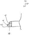
- FIG. 1 is a schematic depiction of a perspective view of a system including the component and the clamping element according to an exemplary embodiment
- FIG. 2 is a schematic depiction of an enlarged section of FIG. 1 ;
- FIG. 3 is a schematic depiction of a sectional view through a clamping element according to an exemplary embodiment.
- identical reference numbers designate identical or comparable components.
- summarizing reference numbers are used for components and objects that appear multiple times in an exemplary embodiment or in an illustration, but that are described together in terms of one or more common features.
- Components or objects that are described with identical or summarizing reference numbers can be identical with respect to individual, multiple, or all features, for example their dimensions, but possibly also embodied differently provided the description does not explicitly or implicitly indicate otherwise.
- FIG. 1 shows a schematic depiction of a perspective view of a system 1 for machining of a component 2 .
- the system 1 comprises the component 2 .
- the component 2 comprises a base body 3 as well as at least one clamping auxiliary structure 4 .
- the base body 3 includes a plastic as material.
- the system 1 further comprises a clamping element 5 that is configured to clamp the component 2 .
- the clamping element 5 includes at least one clamping jaw 6 .
- the clamping jaw 6 includes at least one counter-clamping auxiliary structure 7 .
- the counter-clamping auxiliary structure 7 is configured to be in engagement with the clamping auxiliary structure 4 such that the component is fixed and/or positioned in an interference-fit manner in axial direction M with respect to the clamping element 5 .
- the component 2 is a semi-finished product made from a plastic. For example, it can be machined or turned in order to produce a seal.
- the base body 3 of the component 2 is a circular hollow cylinder. The further details are described based on the enlarged depiction in FIG. 2 .
- the adapter 8 is attached to the base body 3 .
- the adapter 8 is a plastic ring that has an inner diameter that approximately corresponds to the outer diameter of the base body 3 .
- An outer diameter of the adapter 8 here is larger than the outer diameter of the base body 3 .
- the adapter 8 can include a different material than the base body 3 , however, possibly also a plastic.
- the adapter 8 can, for example, be welded to the base body 3 .
- a reason for using the adapter 8 can be, for example, to enlarge a diameter of the base body 3 such that it can be better clamped in the clamping element 5 .
- the adapter 8 also comprises the clamping auxiliary structure 4 . In some further, not-depicted exemplary embodiment the clamping auxiliary structure can also be disposed directly on the base body. In these cases the adapter can the be omitted or nonetheless be present.
- FIG. 3 shows a schematic depiction of a cross-section through the adapter 8 .
- the clamping auxiliary structure 4 can also be seen in the cross-section.
- the clamping auxiliary structure 4 is a recess with respect to a surface 9 of the adapter 8 .
- a shoulder thereby arises including an end surface 10 facing in the axial direction.
- the clamping auxiliary structure 4 is thus configured as a recess.
- the counter-clamping auxiliary structure 7 on the clamping jaw 6 is configured as a radial protrusion that abuts on the end side 10 in the axial direction.
- the counter-clamping auxiliary structure 7 is not formed on the clamping jaw 6 completely along the circumferential direction U, but rather interrupted by an arcuate recess 11 .
- a counter-clamping auxiliary structure 7 - a and a counter-clamping auxiliary structure 7 - b thereby respectively arise on ends of the clamping jaw 6 directed in circumferential direction U.
- a radial extension of the counter-clamping auxiliary structure 7 - a here can have, for example, at least 1%, 2%, 3%, 4%, 5%, or 10% of an outer diameter of the component 2 and/or at most 10%, 9%, or 8%.
- a single clamping jaw 6 includes two counter-clamping auxiliary structures 7 - a and 7 - b that are spaced from each other in circumferential direction U.
- each clamping jaw can also have only one counter-clamping auxiliary structure.
- a clamping section 11 of the clamping jaw 6 adjacent in the axial direction or its radially inwardly directed surface abuts in the radial direction on the surface 9 of the adapter 8 .
- this surface can also be spaced from the adapter.
- the counter-clamping auxiliary structure 7 protrudes in the radial direction farther radially inward than the clamping section 11 .
- the clamping element 5 comprises two further clamping jaws, namely the clamping jaw 6 - a that can be seen in FIG. 1 and a further, not-depicted clamping jaw.
- the three clamping jaws are each disposed spaced with respect to one another in the circumferential direction at an angle of 120°.
- a different number of clamping jaws can also be provided.
- it can be an interference-fit clamping system for plastic semi-finished products on CNC lathes or other lathes.
- the attaching of the component which can also be referred to as semi-finished product, can be effected by an interference fit and not by friction as with conventional clamping systems.
- clamping forces can thereby be reduced and the deforming of the component or of the plastic semi-finished product at least reduced or completely avoided.
- a clamping chuck with respectively three identical jaws can cover a variety of diameters, for example also larger than 30 mm, 40 mm, 50 mm, 60 mm, 70 mm, 80 mm, 90 mm, 100 mm, 120 mm, 130 mm, 140 mm, 150 mm, 200 mm, 250 mm, 300 mm, or 350 mm, and less than 400 mm, 450 mm, or 300 mm.
- the clamping jaws 6 can, for example, be equipped with a hook as counter-clamping auxiliary structure 7 , which hook engages in a corresponding groove that serves as clamping auxiliary structure in the component 2 or the semi-finished product.
- the dimensions of the hook of the clamping jaw 7 and the groove in the component 2 are matched to each other such that an interference-fit fixing can be made possible.
- the producing of the groove or of the recess in the semi-finished product does not represent increased expense.
- three clamping jaws can be moved inward. The component 2 can thereby be clamped.
- the costs for clamping devices can thereby decrease, since a smaller number clamping-jaw sets are needed.
- the clamping element can possibly be used for a larger range of diameters.
- the component can be clamped more securely since it is clamped in the axial direction in an interference-fit manner and not only by friction.
- costs can possibly decrease in ongoing operation since the time for a jaw change is reduced.
- additional customer retention can possibly be achieved since in some exemplary embodiments the clamping jaws can only be used with the corresponding components or semi-finished parts.
- the clamping element can be, for example, a three-jaw manual clamping chuck.
- the system or the clamping element and the component can be used not only as described for the Figures, for the manufacturing of seals from a plastic semi-finished product, but also for the manufacturing of all possible components that can be produced from plastic in a turning process, for example, cages, bearing discs, sliding discs, spacers, or the like.
Landscapes
- Engineering & Computer Science (AREA)
- Mechanical Engineering (AREA)
- Gripping On Spindles (AREA)
Abstract
Description
-
- 1 System
Claims (13)
Applications Claiming Priority (3)
| Application Number | Priority Date | Filing Date | Title |
|---|---|---|---|
| DE102016211905 | 2016-06-30 | ||
| DE102016211905.2A DE102016211905A1 (en) | 2016-06-30 | 2016-06-30 | System for machining a component and component and clamping element for the system |
| DE102016211905.2 | 2016-06-30 |
Publications (2)
| Publication Number | Publication Date |
|---|---|
| US20180001393A1 US20180001393A1 (en) | 2018-01-04 |
| US10695843B2 true US10695843B2 (en) | 2020-06-30 |
Family
ID=60662720
Family Applications (1)
| Application Number | Title | Priority Date | Filing Date |
|---|---|---|---|
| US15/636,796 Active 2037-10-22 US10695843B2 (en) | 2016-06-30 | 2017-06-29 | System for machining of a component, and component and clamping element for the system |
Country Status (4)
| Country | Link |
|---|---|
| US (1) | US10695843B2 (en) |
| CN (1) | CN107553564B (en) |
| AT (1) | AT518795B1 (en) |
| DE (1) | DE102016211905A1 (en) |
Families Citing this family (6)
| Publication number | Priority date | Publication date | Assignee | Title |
|---|---|---|---|---|
| CN111156883B (en) * | 2020-01-02 | 2022-04-12 | 北京半导体专用设备研究所(中国电子科技集团公司第四十五研究所) | Fixing device and hollow columnar device testing equipment using same |
| CN111842941B (en) * | 2020-08-20 | 2025-08-01 | 广东东晟密封科技有限公司 | Automatic feeding system and numerically controlled lathe butt joint sealing piece and application thereof |
| CN112059112A (en) * | 2020-09-23 | 2020-12-11 | 中国船舶重工集团柴油机有限公司 | Process and tool for reducing deformation of annular cast thin-wall part after machining and casting |
| CN113385958B (en) * | 2021-06-10 | 2022-11-04 | 青海高等职业技术学院(海东市中等职业技术学校) | High-precision centering fixture for numerical control machine tool |
| CN114227325A (en) * | 2022-02-10 | 2022-03-25 | 宁波江丰电子材料股份有限公司 | Lathe machining clamp for thin-wall parts |
| CN119635531B (en) * | 2023-09-15 | 2025-11-25 | 中国航发商用航空发动机有限责任公司 | A clamping and positioning device and a clamping and positioning method |
Citations (17)
| Publication number | Priority date | Publication date | Assignee | Title |
|---|---|---|---|---|
| US1859710A (en) * | 1931-09-28 | 1932-05-24 | Frank Forthaller | Bottle or jar cap |
| US2095960A (en) * | 1931-10-02 | 1937-10-19 | American Can Co | Vacuum machine |
| US2209892A (en) * | 1936-03-30 | 1940-07-30 | American Flange & Mfg | Closing tool |
| US2579775A (en) * | 1946-04-24 | 1951-12-25 | American Seal Kap Corp | Capping head |
| US2647523A (en) * | 1950-03-16 | 1953-08-04 | Jr Ferdinand A Vollender | Ash tray adapter |
| US2903230A (en) * | 1953-12-21 | 1959-09-08 | John H Schachte | Automatic weighing and loading apparatus |
| US2931258A (en) * | 1959-02-09 | 1960-04-05 | Foley Mfg Company | Opener for screw caps |
| US3205570A (en) * | 1964-01-20 | 1965-09-14 | Louis H Morin | Method of casting and trimming sliders in multiple, utilizing unitary bifurcated cores |
| US3959426A (en) * | 1973-06-29 | 1976-05-25 | Phillips Petroleum Company | Method of transferring and aligning parisons using clamping jaws with offset tines |
| US3967847A (en) * | 1975-09-15 | 1976-07-06 | Anchor Hocking Corporation | Chuck apparatus for glass container coating line |
| US4088239A (en) * | 1977-05-23 | 1978-05-09 | Owens-Illinois, Inc. | Plastic drum and metal handling ring |
| US4319543A (en) * | 1980-08-25 | 1982-03-16 | Anchor Hocking Corporation | Container masking and coating apparatus |
| US6015062A (en) * | 1997-11-17 | 2000-01-18 | Dayton Systems Group, Inc. | Resealable beverage container and top therefor |
| US20090224112A1 (en) * | 2006-06-16 | 2009-09-10 | Raymond Carrasco | Detachable musical base for baby bottle |
| CN103786046A (en) | 2014-02-27 | 2014-05-14 | 济南重工股份有限公司 | Turning tool structure for thin-walled work-piece |
| CN104002166A (en) | 2014-05-30 | 2014-08-27 | 济南重工股份有限公司 | Auxiliary tooling and process for machining thin wall annular part |
| US20180029864A1 (en) * | 2012-10-10 | 2018-02-01 | Raymond Wilson Blackburn | Fluid dispenser with isolation membrane |
Family Cites Families (3)
| Publication number | Priority date | Publication date | Assignee | Title |
|---|---|---|---|---|
| CN2829946Y (en) * | 2005-09-30 | 2006-10-25 | 中信重型机械公司 | Eight-claw auto centering clamping device of vertically working ring |
| CN201519884U (en) * | 2009-09-28 | 2010-07-07 | 上海交运汽车动力系统有限公司 | Frock clamp for manufacturing automobile speed-changer output supporting frames |
| CN204247998U (en) * | 2014-11-19 | 2015-04-08 | 陈江 | A kind of can the scroll chuck of chucking grooves |
-
2016
- 2016-06-30 DE DE102016211905.2A patent/DE102016211905A1/en active Pending
-
2017
- 2017-05-05 AT ATA50368/2017A patent/AT518795B1/en active
- 2017-06-28 CN CN201710507230.0A patent/CN107553564B/en active Active
- 2017-06-29 US US15/636,796 patent/US10695843B2/en active Active
Patent Citations (17)
| Publication number | Priority date | Publication date | Assignee | Title |
|---|---|---|---|---|
| US1859710A (en) * | 1931-09-28 | 1932-05-24 | Frank Forthaller | Bottle or jar cap |
| US2095960A (en) * | 1931-10-02 | 1937-10-19 | American Can Co | Vacuum machine |
| US2209892A (en) * | 1936-03-30 | 1940-07-30 | American Flange & Mfg | Closing tool |
| US2579775A (en) * | 1946-04-24 | 1951-12-25 | American Seal Kap Corp | Capping head |
| US2647523A (en) * | 1950-03-16 | 1953-08-04 | Jr Ferdinand A Vollender | Ash tray adapter |
| US2903230A (en) * | 1953-12-21 | 1959-09-08 | John H Schachte | Automatic weighing and loading apparatus |
| US2931258A (en) * | 1959-02-09 | 1960-04-05 | Foley Mfg Company | Opener for screw caps |
| US3205570A (en) * | 1964-01-20 | 1965-09-14 | Louis H Morin | Method of casting and trimming sliders in multiple, utilizing unitary bifurcated cores |
| US3959426A (en) * | 1973-06-29 | 1976-05-25 | Phillips Petroleum Company | Method of transferring and aligning parisons using clamping jaws with offset tines |
| US3967847A (en) * | 1975-09-15 | 1976-07-06 | Anchor Hocking Corporation | Chuck apparatus for glass container coating line |
| US4088239A (en) * | 1977-05-23 | 1978-05-09 | Owens-Illinois, Inc. | Plastic drum and metal handling ring |
| US4319543A (en) * | 1980-08-25 | 1982-03-16 | Anchor Hocking Corporation | Container masking and coating apparatus |
| US6015062A (en) * | 1997-11-17 | 2000-01-18 | Dayton Systems Group, Inc. | Resealable beverage container and top therefor |
| US20090224112A1 (en) * | 2006-06-16 | 2009-09-10 | Raymond Carrasco | Detachable musical base for baby bottle |
| US20180029864A1 (en) * | 2012-10-10 | 2018-02-01 | Raymond Wilson Blackburn | Fluid dispenser with isolation membrane |
| CN103786046A (en) | 2014-02-27 | 2014-05-14 | 济南重工股份有限公司 | Turning tool structure for thin-walled work-piece |
| CN104002166A (en) | 2014-05-30 | 2014-08-27 | 济南重工股份有限公司 | Auxiliary tooling and process for machining thin wall annular part |
Also Published As
| Publication number | Publication date |
|---|---|
| AT518795B1 (en) | 2018-08-15 |
| CN107553564B (en) | 2021-09-07 |
| DE102016211905A1 (en) | 2018-01-04 |
| US20180001393A1 (en) | 2018-01-04 |
| CN107553564A (en) | 2018-01-09 |
| AT518795A3 (en) | 2018-08-15 |
| AT518795A2 (en) | 2018-01-15 |
Similar Documents
| Publication | Publication Date | Title |
|---|---|---|
| US10695843B2 (en) | System for machining of a component, and component and clamping element for the system | |
| US9388921B2 (en) | Plug-in piece | |
| US3117797A (en) | Expandable or contractible workpiece holder | |
| US9856918B2 (en) | Bearing and housing support for intermediate drive shaft | |
| AU776349B2 (en) | Pipe fitting | |
| US11117231B2 (en) | Fixture for machining parts and method of using same | |
| US9833846B2 (en) | Rotary cutting tool with high-pressure, threaded coolant cap | |
| CN105014451A (en) | Wedge pushing type two-way spindle chuck of double-head car | |
| CA2969507A1 (en) | Bonded seal with integral backup ring | |
| US20150217385A1 (en) | Centering device | |
| RU153048U1 (en) | LATERAL CARTRIDGE FOR ATTACHING THE ROCKET ENGINE | |
| US9950420B2 (en) | Elastic protective cap to be placed over a polygonal tool shank | |
| JP2006234117A (en) | Resin pipe | |
| CA3095388C (en) | Dual barrier seal | |
| JP7290327B2 (en) | Collet device | |
| US20120219368A1 (en) | Cutter body and locking screw therefor | |
| US7401544B2 (en) | Plunger with annular exterior seals and method of installing annular seals on an exterior surface of a plunger | |
| AU2012320231B2 (en) | Method and apparatus for gripping | |
| EP3132161B1 (en) | Ez-seal assembly joining fluid pathways | |
| US20010008705A1 (en) | Welding construction | |
| US10183461B2 (en) | Multipurpose segmented turning segments and rings | |
| US10518335B2 (en) | Device for holding a workpiece | |
| JP7285243B2 (en) | plumbing fittings | |
| US11725758B2 (en) | Fluid line quick connector with spacer having angled surface(s) | |
| CN208503459U (en) | Resin ring |
Legal Events
| Date | Code | Title | Description |
|---|---|---|---|
| AS | Assignment |
Owner name: AKTIEBOLAGET SKF, SWEDEN Free format text: ASSIGNMENT OF ASSIGNORS INTEREST;ASSIGNORS:PFANDL, ERICH;MOITZI, JOHANN;REEL/FRAME:042861/0864 Effective date: 20170518 |
|
| STPP | Information on status: patent application and granting procedure in general |
Free format text: NON FINAL ACTION MAILED |
|
| STPP | Information on status: patent application and granting procedure in general |
Free format text: RESPONSE TO NON-FINAL OFFICE ACTION ENTERED AND FORWARDED TO EXAMINER |
|
| STPP | Information on status: patent application and granting procedure in general |
Free format text: NOTICE OF ALLOWANCE MAILED -- APPLICATION RECEIVED IN OFFICE OF PUBLICATIONS |
|
| STPP | Information on status: patent application and granting procedure in general |
Free format text: DOCKETED NEW CASE - READY FOR EXAMINATION |
|
| STCF | Information on status: patent grant |
Free format text: PATENTED CASE |
|
| MAFP | Maintenance fee payment |
Free format text: PAYMENT OF MAINTENANCE FEE, 4TH YEAR, LARGE ENTITY (ORIGINAL EVENT CODE: M1551); ENTITY STATUS OF PATENT OWNER: LARGE ENTITY Year of fee payment: 4 |