US1069558A - Coin-controlled taxicab-controller. - Google Patents
Coin-controlled taxicab-controller. Download PDFInfo
- Publication number
- US1069558A US1069558A US68783012A US1912687830A US1069558A US 1069558 A US1069558 A US 1069558A US 68783012 A US68783012 A US 68783012A US 1912687830 A US1912687830 A US 1912687830A US 1069558 A US1069558 A US 1069558A
- Authority
- US
- United States
- Prior art keywords
- coin
- chute
- circuit
- switch
- arm
- Prior art date
- Legal status (The legal status is an assumption and is not a legal conclusion. Google has not performed a legal analysis and makes no representation as to the accuracy of the status listed.)
- Expired - Lifetime
Links
- 239000002184 metal Substances 0.000 description 18
- 239000011435 rock Substances 0.000 description 5
- 238000010276 construction Methods 0.000 description 3
- 239000011521 glass Substances 0.000 description 2
- 239000011810 insulating material Substances 0.000 description 1
- 230000004048 modification Effects 0.000 description 1
- 238000012986 modification Methods 0.000 description 1
- 230000011664 signaling Effects 0.000 description 1
Images


Classifications
-
- G—PHYSICS
- G07—CHECKING-DEVICES
- G07F—COIN-FREED OR LIKE APPARATUS
- G07F5/00—Coin-actuated mechanisms; Interlocks
- G07F5/20—Coin-actuated mechanisms; Interlocks specially adapted for registering coins as credit, e.g. mechanically actuated
- G07F5/22—Coin-actuated mechanisms; Interlocks specially adapted for registering coins as credit, e.g. mechanically actuated electrically actuated
Definitions
- Patented Au 5, 1913 Patented Au 5, 1913.
- This, invention relates to'controlling devices for taxicabs and the like, and has for a coin-conwhich makes to pay for a its primary object toprovide trolleddevice of this character,
- Another object of this invention is to provide a coin-controlled taxicab controller, which, when a coin is deposited therein, will he set so as to start the engine, and which, after the taxicab has .run the distance that the passenger is entitled to ride by the deposit of such coin, will not only stop the engine, but, also, will sound an alarm and indicate that it is necessary for the passen ger to deposit another coin in the device in order to ride farther.
- the present invention contemplates the provision of cab controller particularly adapted for use in. conjunction with the register, which constitutes the suhjectanatter of the United States Letters Patent No. 676,519, granted larly" when said register is used in conjunction with the magnetic tachometer illustrated and described in the United States Letters Patent No. 745,468, granted to A. P. and 0. HI ⁇ Varner, December 1, 1903.
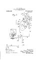
- Figure 1 is a perspective view sic-wing the real-side of the box which inoloses some of the parts of the device;
- Fig. 2 is a perspective view showing the front side of same;
- 11 ig. 3 is a perspective view showing the box open to exposeithe parts within same;
- Fig. 4 is a detailed view of the coin switch;
- Fig. 5 is a. detailed view of the coin chutes and switch;
- Fig. 6 is a sectional view, on an enlarged scale, on the line (r-(3,
- Fig. 8 is a diagrammatical view of an alternate form of wiring.
- a box or case 1 which incloses some of the parts of the controlling device is fastened to the body of the taxicab or the like (not shown in the drawings) by any suitable means and is preferably positioned so that same is in convenient reach of the chauffeur and, also, so that the rear side thereof is exposed to the passenger for the purpose hereinafter described.
- the front side2 of the box 1 is preferably hinged and is normally Fig. 4; Fig.
- the top of -the box 1 contains a slot 4: which is located above a coin-chute 5, the by plates 6, 7, and 8 which are preferably fastened to the inner face of the hinged side 2 by screws 9, 10, and 11, respectively.
- Said plates 6, 7, and S are preferably arranged so thatthe chute 5 slopes downwardly from the slot 4, and said plates 6 and '4 bear flanges 12 and 13, respectively, for the purpose of preventing the coins from falling out of said chute.
- a revoluble coin-switch 14 is located at the lower end of the chute 5 and contains a pocket 15 into which the coins 16 pass successively from the chute 5, said pocket being of such size that same will hold only one coin.
- a pin 21 or the like is secured to the hinged side 2 of the box 1 and-is located in the path of movement of lugs 22 and 28 borne by the shank 18 of button 17 in order to limit the morement of said coin-switch.
- the lug 22 engages pin 21, but, when the button 17 is rotated so as to rock the coin-switch 14, the lug 22 moves out-of engagement with pin 21 and lug limiting the movement of the coin-switch 1t engages said pin, thereby to the extent necessary to cause the coin 16 in the pocket 15 to discharge into the coint'lllllIC 19.
- the pocket 15 in the coin-switch 14 is arranged so that, when "said coin-switch rotated to the position to cause the coin 16 in said pocket to discharge into the coin- ('lllltO l9, the next following coin in coinchute 5 cannot enter said pocket until said coin-switch has returned to its initial position.
- the coin-chute 19 is formed'by an exten sion 24 of plate 7 and the arm 25 of a bellerank plate 26 which is pivoted at 27 to the hinged side 2 of box 1, said extension 24 and arm 25 being provided with flanges 28 and 29, respectively, which prevent the coins from falling out of said chute.
- a spring 30 holds the other arm 31 of the bell-crank plate 26 normally in engagement "with a metallic stop 32 and thereby holds the arm 25 normally in an inclined position relative to the extension 24 of plate 7, so that said arm 25 and extension 24 converge downwardly.
- the bell 34 is con-v nected in series with an incandescent lamp 36 to an electric battery 37 by means of a wire 38 which leads from one terminal of said battery to a binding post 38 secured to the inner face of the side 2 of box 1, said binding post 38 'being connected with one of the binding posts 39 of said bell by mean 3 of a wire 39.
- a wire 40 leads from the other binding post 39 of hell 34 to a binding post 41 which has a ground connect-ion with the frame of the taxicab by means of a wire 42.
- Said register 49 is preferably of the type of register which constitutes the subject-matter of the abovementioned Patent No. 676,519, granted to C. H. Veeder, June 18, 1901, and is secured to and operatively connected with the magnetic tachometer 50 in the usual manner, which tachometer is preferably of 'the type illustrated and described in the above-mentioned Patent No. 745,468, granted to A. P. and C.
- said lever being preferably in the form of a bell-crank which is pivoted at 53 to said register and having a spring54 attached thereto for the purpose of holding the projection 52 n said lever in engagement with said ring H.
- the ring H is preferably adapted to make one complete revolution for each mile that the taxicab runs, and has a notch 55 formed, in its periphery in order to allow the projection 51 on lever 52 to enter same, when said ring H has been rotated sufliciently to move said notch into registration with said projection.
- the projection 51 borne by lever rides 'upon the periphery of ring H, the arm 56 of said lever is thereby held out of engage- I ment with the metal post 47, thus breaking The register 49 and the battery circuit.
- tachometer 50 have a ground connection with the frame of the taxicab and, when the ring H is rotated sufliciently to bring the notch 55 into registration with the projection 51 on lever 52, the' pull of spring 54 causes said projection to enter said notch and thereby moves the arm 56 of said lever into engagement with the metal post 47, thereby closing the battery circuit, with the result of causingthe lamp 36 to light and the bell 34 to ring.
- the closingof the battery circuit causes the clapper 33 to vibrate and thereby not only cause same to ring the bell, but also, l'tiClit-t the plate 26 clockwise Fig. 7, whereby the arm 25 of said plate 26 releases the coin 16 in chute 19 whereupon said coin drops into the bottom of the box 1.
- the battery circuit remains closed as long as. the arm 56 of lever 52 engages the metal post 47, and, in order that this shall be for a relatively short time, the notch 55 in While formed V-shaped.
- ring H is formed relatively shallow and said notch and projection 51 are preferably The'bell 34 rings and the lamp 36 burns as long as the arm 56 of lever 52 engages the metal post 47 (it being, of course, understood that the switch is closed), but when the taxicab has run sufliciently to cause further rotation of ring H, said ring forces the projection 51 on lever 52 out of notch 55 and thereby moves the arm 56 of said lever out of engagement with said post, thus breaking the battery circuit, with theresult that not only the bell 34 stops ringing and the lamp 36 ceases to burn until the battery circuit is again closed, but, also, that the engine (not shown) is caused to stop in the manner about to be described.
- Said lamp 36 is located in front of a glass covered opening 57 in the rear side of box 1, so as to be in the view of the passenger, and, if desired, the word Pay or any other suitable word or expression may appear on the glass that covers said opening, in order to indicate that it is necessary to deposit another coin 16 from the chute 5 into the chute 19 by Q means 'of the coin-switch 14, as hereinafter post 41 and described.
- a wire 58 leads from a magneto 59 to one of the poles 60 of switch 45 and from the other pole 60 of said swltch a wire 61 leads to the metallic stop 32, said magneto being preferably 'of the Bosch high tension type and having the usual ground connection with the frame of the taxicab.
- a wire 62 leads from the .pivot 27 to the binding thereby completes the magneto circuit for the reason that the wire 42, which leads from said binding p0st,'has a ground connection with the frame of the taxicab.
- the wire 42 thus affords a ground connection for the battery circuit and, also, for the magneto circuit.
- the magneto 59 has the usual connections with the cylinders of the engine, and as the former is preferably of the Bosch high tension type, it is necessary for the circuit to be broken in order to allow the engine to run.
- the breaking of the magneto circuit may be accomplished either by opening the switch 45 or by allowing a coin 16 to fall into the chute 19 as hereinabove described.
- the switch 45 is closed.
- the coin-switch 14 is rotated teallow a coin 16 to fall into chute 19,
- chute 19 is intended to hold only one coin at a time
- the chute 5 may be designed to hold either one or any number of coins. Furthermore, if it is desired to adjust the coin chutes 5 and 19 for the coin-switch 14 can be replaced by' one of the proper size and, by removing the screws 10, the plate 12 and its extension 24 can be adjusted with relation to the plates 6 and 26, so as to change the chutes 5 and 19 to the proper sizes. If necessary, the plate 8 may be replaced by a larger or a smaller one.
- the wires 38, 42, and 61 may be incased in a cable and the latter passed through an opening in the box 1 as illustrated in Fig. 3.
- a diagrammatic-a1 view of the wiring for same is depicted, when the device is used on a taxicab having a pricircuit from a battery or other suitable source.
- a wire 63 leads from one terminal of the battery 37 to a spark coil 63 and from said spark coil a wire 64 leads to the timer 64, the latter --having the usual connections with the engine cylinders (not shown), and a wire 65 that the other terminal of'said battery has a ground connection with the frame of the taxicab.
- a wire 66 leads from the timer 64 to the extension 24 of plate 7 and is con nected to one of the poles 67 of a double rocks the plate 26, which, in turn, releases A pole switch 68 by means of a wire 69.
- a Wire. 70 which leads from the other pole 67 of switch 68, has a ground connection with the frame of the taxicab, in order to complete the battery circuit when the switch 68 is turned to connect the poles 6T.
- a wire 71 leads from one of the poles 72 of switch 68 to the metal post 47 and a wire 73 leads from the other pole 72 of Said switch to the binding post 38
- the wire 39 which leads from the binding post 38 to one of the binding posts 39 of bell 34, connects the lamp 36 in series with said bell, the other binding post 39 of said bell and the pivot 27 of plate 26 being connected to the bindin posts 41 by the wires 40 and 62, respectively, and the wire 42, which leads from said binding post 41, being connected with a metal post 74 that is secured to the block 48.
- the metal posts 47 and 74 are spaced apart, so as to allow the arm 56 of lever 52 to extend therebetween, and when the projection 51 on lever 52 rides on the periphery of ring H, the arm 56 engages the metal post 74, but when the projection 51 on said lever enters notch in said ring, the arm 56 moves out of engagement with said post 74 and into engagement with -post 47.
- the register 49 and the tachometer 50 have a ground connection with the frame of the taxicab, and when the switch 68 is turned, so as-to connect the poles 72, and a coin 16 is deposited in chute 19 as hereinabove described, said coin closes the circuit and the current passes through the wires 42 and 62, if the arm 56 of lever 52 engages the metal post 74, or through the wires 62, 40, 39 73, and 71 and switch 68, if said arm engages the metal post 47.
- the arm 56 of said lever engages the metal post 74 and thereby closes the circuit through the wires 42 and
- the operation of the device will be largely evident from the above description, but may be summarized as follows:
- the passenger deposits the proper coin 16 in the chute 5 and the chauffeur rotates the coin-switch 14 by means of a button 17. so as to cause one coin to drop into the chute 19.
- the spring 54 causes said projection 51-to enter said notch and thereby moves the arm 56 of said lever into engagement with the metal post 47, thereby closing the lamp and bell circuit, with the result of causing the lamp 36 to burn and the bell 34 to ring.
- the trip-register of the re ister 49 aflords a means by which the chauffeur can keep a check on the length of each trip in the usual manner, and if it happens upon starting a trip that a coin 16 is deposited in chute 19 while the notch 55 is in such position that the ring H will make only part of a revolution before the lamp and bell circuit is closed to release the coin 16 in chute 19, thereby to stop the engine, the chauffeur can break the lamp and bell circuit in the manner hereinabove described, in order to run' the taxicab until the trip-register indicates the distance the passenger is entitled to ride for the payment of said coin,
- this device it is necessary for the passenger to pay in advance for each mile or fraction thereof, thus obviating the trouble and expense occasioned sometimes, when the chauffeur endeavors to collect at the completion pf a trip, and, also, preventing the loss of a are.
- ring H contains only one notch as hereinabove described and illustrated in the drawit should be understood that while the ings, so that the lamp and bell circuit is closed at the completion of each mile run,
- a coin-controlled mechanism of the character specified the combination of a coin chute, a spring-controlled rocking member constituting a portion of said chute and extending into the path of the coin for engagement therewith, an electric circuit, a signal included in said circuit and provided with a vibratory member, means for 'clos ing said circuit, and a connection between said vibratory member and said rocking member for operating the latter when the signal is actuated consequent upon the closing of said circuit to release the coin from such engagement.
- a coin-controlled mechanism of the character specified the combination of a coin-chute, a movable member constituting a portion of said chute, means for normally holding said member in position to'engage a coin, an electric circuit, a signal included therein and provided with a movable operating member, means for closing said circuit, and a'conncction between said signal-operating memberand said movable chute member for drawing the latter away from the coin when said signal is operated consequent circuits and constituting upon the closing of said circuit to release the coin.
- a coin-controlled mechanism of the character specified the combination of a coin chute, a movable member constituting a portion of said chute, means for normally holding said member in position to engage a coin, an electric circuit, a signal included therein and embodying a resonant element and a vibratory impact element adapted to strike the same, means for closing said circuit, and a connection between said impact element and said movable chute member for drawing the latter away from the coin when said signal is operated consequent upon the closing of said circuit torelease the coin.
- a coin-controlled mechanism of the character specified the combination of a coin chute, a pair of electric circuits, a movable switch member included in one of said a portion of said chute, said member extending into the path of the coin for engagement thereby, a switch included in the other circuit, means included in the first circuit for operating said switch, and signaling means included in the second circuit and connected with said movable switch member 'for releasing the latter from engagement with the coin.
Landscapes
- Physics & Mathematics (AREA)
- General Physics & Mathematics (AREA)
- Control Of Vending Devices And Auxiliary Devices For Vending Devices (AREA)
Description
,4 SHEETSBHEET 1.
Patented Au 5, 1913.
W. L. MAJORSJ COIN CONTROLLED TAXIOAB CONTROLLER; 7
APPLICATION FILED APR. 1, 1912.
W. L. MAJ ORS.
00m CONTROLLED TAXIOAB CONTROLLER.
APPLICATION FILED APR.1, 1912.
Patented Aug. 5,1913.
4 SHEETS-SHEET 2.
W. L. MAJ OBS.
00m GONTROLLED TAXIGAB CONTROLLER.
APPLICATION FILED APR. 1, 1912.
Patented Aug. 5, 1913.
4 SHEETS-SHEET 3.
W. L. MAJ OBS.
COIN CONTROLLED TAXIGAB CONTROLLER.
APPLIOATION FILED APR. 1, 1912.
Patented Aug. 5, 1913.
4 SHEETS-SHEET 4.
an s
WALTER L. MAJ'OBS, OF
COIN-CONTROLLED TAXIGAB-CONTROLLER.
no oasrs.
Specification of Letters Patent.
Patented Aug. 5, 1913.
Application filed April 1, 1912. Serial No. 687,830.
lers, of which the following is a specificato C. H. 'Veeder, June pointed out in the claims.
it necessary for the passenger tion.
This, invention relates to'controlling devices for taxicabs and the like, and has for a coin-conwhich makes to pay for a its primary object toprovide trolleddevice of this character,
ride upon entering the taxicab.
Another object of this invention is to provide a coin-controlled taxicab controller, which, when a coin is deposited therein, will he set so as to start the engine, and which, after the taxicab has .run the distance that the passenger is entitled to ride by the deposit of such coin, will not only stop the engine, but, also, will sound an alarm and indicate that it is necessary for the passen ger to deposit another coin in the device in order to ride farther.
Further, the present invention contemplates the provision of cab controller particularly adapted for use in. conjunction with the register, which constitutes the suhjectanatter of the United States Letters Patent No. 676,519, granted larly" when said register is used in conjunction with the magnetic tachometer illustrated and described in the United States Letters Patent No. 745,468, granted to A. P. and 0. HI \Varner, December 1, 1903.
With these objects in view the present invention comprises certain novel features of construction and arrangement of parts as will be hereinafter more fully described and hi the accompanying drawings forming part of this specification, in which like numhers of reft rence denote like parts wherever t iey occur, Figure 1 is a perspective view sic-wing the real-side of the box which inoloses some of the parts of the device; Fig. 2 is a perspective view showing the front side of same; 11 ig. 3 is a perspective view showing the box open to exposeithe parts within same; Fig. 4 is a detailed view of the coin switch; Fig. 5 is a. detailed view of the coin chutes and switch; Fig. 6 is a sectional view, on an enlarged scale, on the line (r-(3,
latter being formed a coin-controlled taxi- 18, 1901, and particu-' into a coin-chute 19 7 is a diagrammatical view of the wiring; and Fig. 8 is a diagrammatical view of an alternate form of wiring.
A box or case 1, which incloses some of the parts of the controlling device is fastened to the body of the taxicab or the like (not shown in the drawings) by any suitable means and is preferably positioned so that same is in convenient reach of the chauffeur and, also, so that the rear side thereof is exposed to the passenger for the purpose hereinafter described. The front side2 of the box 1 is preferably hinged and is normally Fig. 4; Fig.
held closed by a lock 3 or other suitable means. The top of -the box 1 contains a slot 4: which is located above a coin-chute 5, the by plates 6, 7, and 8 which are preferably fastened to the inner face of the hinged side 2 by screws 9, 10, and 11, respectively. Said plates 6, 7, and S are preferably arranged so thatthe chute 5 slopes downwardly from the slot 4, and said plates 6 and '4 bear flanges 12 and 13, respectively, for the purpose of preventing the coins from falling out of said chute. A revoluble coin-switch 14 is located at the lower end of the chute 5 and contains a pocket 15 into which the coins 16 pass successively from the chute 5, said pocket being of such size that same will hold only one coin. A button 17 having a shank 18, which extends through an opening in the side Qof box 1 and supports the coin-switch 14, affords a means for rotating said coin-switch, in order to discharge a coin from the latter for the purpose hereinafter described. A spring 20, which is preferably coiled about the shank 18 of button 17, holds the coin-switch '14 normally in position to receive a com 16 from chute 5, and is adapted to return said coin-switch to its normal position after same has been rotated to cause the coin .16" therein to discharge into the coin-chute 19. A pin 21 or the like is secured to the hinged side 2 of the box 1 and-is located in the path of movement of lugs 22 and 28 borne by the shank 18 of button 17 in order to limit the morement of said coin-switch. \Vhile the coins-witch' 14 is in its normal position, the lug 22 engages pin 21, but, when the button 17 is rotated so as to rock the coin-switch 14, the lug 22 moves out-of engagement with pin 21 and lug limiting the movement of the coin-switch 1t engages said pin, thereby to the extent necessary to cause the coin 16 in the pocket 15 to discharge into the coint'lllllIC 19. The pocket 15 in the coin-switch 14 is arranged so that, when "said coin-switch rotated to the position to cause the coin 16 in said pocket to discharge into the coin- ('lllltO l9, the next following coin in coinchute 5 cannot enter said pocket until said coin-switch has returned to its initial position.
The coin-chute 19 is formed'by an exten sion 24 of plate 7 and the arm 25 of a bellerank plate 26 which is pivoted at 27 to the hinged side 2 of box 1, said extension 24 and arm 25 being provided with flanges 28 and 29, respectively, which prevent the coins from falling out of said chute. A spring 30 holds the other arm 31 of the bell-crank plate 26 normally in engagement "with a metallic stop 32 and thereby holds the arm 25 normally in an inclined position relative to the extension 24 of plate 7, so that said arm 25 and extension 24 converge downwardly. '-When the coin-switch 14 is rotated so as to cause a coin 16 to discharge therefrom, said coin drops into the chute 19, and,
'by reason of the arm 25 and extension 24 being arranged to converge downwardly, said coin will be caught between said arm 25 and extension 24 and will be held in said chute 19 by the pull of spring 30 on crankplate 26. The coin remains in chute 19 until the crank-plate 26 is rocked in the manner hereinafter described, so as to move the lower end of arm 25 away from extension 24, thereby releasing said coin and allowing same to drop into the bottom of the box 1, whereupon the pull of spring 30 returns the crank-plate 26 to its initial position.
When a coin 16 falls from the coin-switch 14 into the chute 19 and engages the arm 25 of plate 26, it moves said arm slightly to the left, Fig. 3, and therebyrocks said plate 26 sufiieiently to move the arm 31 out of engagement with stop 32 for the purpose hereinafter described, such movement of said arm 25, however, being not sufiicient to allow said coin to drop out of said chute 19. The arm 25 of plate 26 is connected to the clapper 33 of an electric bell '34 by a I cord 35 or other suitable means, andfwhen the circuit of said bell is closed as hereinafter described, the clapper 33 vibrates and thereby rocks the plate 26 sufiiciently to allow the coin 16 to pass from between arm 25 and extension 24. The bell 34 is con-v nected in series with an incandescent lamp 36 to an electric battery 37 by means of a wire 38 which leads from one terminal of said battery to a binding post 38 secured to the inner face of the side 2 of box 1, said binding post 38 'being connected with one of the binding posts 39 of said bell by mean 3 of a wire 39. A wire 40 leads from the other binding post 39 of hell 34 to a binding post 41 which has a ground connect-ion with the frame of the taxicab by means of a wire 42. A. wire 43 leads from the other terminal of the battery 37 to one of the poles 44 of a double pole switch 45, and from the other pole 44 of said switch a wire 46 leads to a metal post'47- which is secured to a block 48 of insulating material, said block being secured to the casing of register 49 by any suitable means. Said register 49 is preferably of the type of register which constitutes the subject-matter of the abovementioned Patent No. 676,519, granted to C. H. Veeder, June 18, 1901, and is secured to and operatively connected with the magnetic tachometer 50 in the usual manner, which tachometer is preferably of 'the type illustrated and described in the above-mentioned Patent No. 745,468, granted to A. P. and C. H. WVarner, December 1, 1903. An opening is formed in one side of the cap A of the register 49, as best seen in Fig. 7, in order to allow a projection 51 borne by lever 52 to engage the periphery of the first or right-hand index ring H of said register,
said lever being preferably in the form of a bell-crank which is pivoted at 53 to said register and having a spring54 attached thereto for the purpose of holding the projection 52 n said lever in engagement with said ring H. The ring H is preferably adapted to make one complete revolution for each mile that the taxicab runs, and has a notch 55 formed, in its periphery in order to allow the projection 51 on lever 52 to enter same, when said ring H has been rotated sufliciently to move said notch into registration with said projection. the projection 51 borne by lever rides 'upon the periphery of ring H, the arm 56 of said lever is thereby held out of engage- I ment with the metal post 47, thus breaking The register 49 and the battery circuit. tachometer 50 have a ground connection with the frame of the taxicab and, when the ring H is rotated sufliciently to bring the notch 55 into registration with the projection 51 on lever 52, the' pull of spring 54 causes said projection to enter said notch and thereby moves the arm 56 of said lever into engagement with the metal post 47, thereby closing the battery circuit, with the result of causingthe lamp 36 to light and the bell 34 to ring. The closingof the battery circuit as just'described causes the clapper 33 to vibrate and thereby not only cause same to ring the bell, but also, l'tiClit-t the plate 26 clockwise Fig. 7, whereby the arm 25 of said plate 26 releases the coin 16 in chute 19 whereupon said coin drops into the bottom of the box 1.
The battery circuit remains closed as long as. the arm 56 of lever 52 engages the metal post 47, and, in order that this shall be for a relatively short time, the notch 55 in While formed V-shaped.
ring H is formed relatively shallow and said notch and projection 51 are preferably The'bell 34 rings and the lamp 36 burns as long as the arm 56 of lever 52 engages the metal post 47 (it being, of course, understood that the switch is closed), but when the taxicab has run sufliciently to cause further rotation of ring H, said ring forces the projection 51 on lever 52 out of notch 55 and thereby moves the arm 56 of said lever out of engagement with said post, thus breaking the battery circuit, with theresult that not only the bell 34 stops ringing and the lamp 36 ceases to burn until the battery circuit is again closed, but, also, that the engine (not shown) is caused to stop in the manner about to be described. Said lamp 36 is located in front of a glass covered opening 57 in the rear side of box 1, so as to be in the view of the passenger, and, if desired, the word Pay or any other suitable word or expression may appear on the glass that covers said opening, in order to indicate that it is necessary to deposit another coin 16 from the chute 5 into the chute 19 by Q means 'of the coin-switch 14, as hereinafter post 41 and described.
A wire 58 leads from a magneto 59 to one of the poles 60 of switch 45 and from the other pole 60 of said swltch a wire 61 leads to the metallic stop 32, said magneto being preferably 'of the Bosch high tension type and having the usual ground connection with the frame of the taxicab. A wire 62 leads from the .pivot 27 to the binding thereby completes the magneto circuit for the reason that the wire 42, which leads from said binding p0st,'has a ground connection with the frame of the taxicab. The wire 42 thus affords a ground connection for the battery circuit and, also, for the magneto circuit. The magneto 59 has the usual connections with the cylinders of the engine, and as the former is preferably of the Bosch high tension type, it is necessary for the circuit to be broken in order to allow the engine to run. The breaking of the magneto circuit may be accomplished either by opening the switch 45 or by allowing a coin 16 to fall into the chute 19 as hereinabove described. v
If the stopping of the taxicab is to be controlled by the battery circuit,,the switch 45 is closed. When the coin-switch 14 is rotated teallow a coin 16 to fall into chute 19,
said coin rocks the plate 26 sufficiently to move the arm 31 of said plate out of engagement with the metal stop 32, thereby break ing the magneto circuit. The magneto cireuit remains broken as long as the coin 16 is held in chute-19, but when the battery circuit is closed as hereinabove described, the vibration of the clapper 33 of bell 34 cuit, with the result of 'mary spark leads from the coin 16 in said chute and allows said coin to drop into the bottom of the box 1, whereupon spring 30- returns the plate 26 to its initial position with the arm 31 in engagement with the metal stop 32, so as to close the magneto circuit. It should be understood that, while the bell 34 is ringing, the pull of spring 30 and the vibration of clapper 33 cause the arm 31 of plate 26 to move into and out of engagement with the metal stop 32, thereby closing and opening the magneto circuit intermittently. This intermittent closing of the magneto circuit, however, does not stop the engine, but the latter continues to run until the battery circuit is broken by the arm 56 of lever 52 being moved out of engagement with. the metal post 47 as hereinabove described, whereupon the clapper ceases to vibrate and the spring 30 holds the arm 31 of plate 26 in engagement with the metal stop 32, thereby closing the magneto cirstopping the engine. When the switch 45 is opened, the same breaks the magneto and battery circuits and thereby allows the engine of the taxicab to run as long as may be desired.
It should be understood that the chute 19 is intended to hold only one coin at a time,
while the chute 5 may be designed to hold either one or any number of coins. Furthermore, if it is desired to adjust the coin chutes 5 and 19 for the coin-switch 14 can be replaced by' one of the proper size and, by removing the screws 10, the plate 12 and its extension 24 can be adjusted with relation to the plates 6 and 26, so as to change the chutes 5 and 19 to the proper sizes. If necessary, the plate 8 may be replaced by a larger or a smaller one.
In order to prevent either the battery circuit or the magneto circuit from being short circuited by the chauffeur or the passenger, the wires 38, 42, and 61 may be incased in a cable and the latter passed through an opening in the box 1 as illustrated in Fig. 3.
In the alternate form of the invention depicted in Fig. 8, a diagrammatic-a1 view of the wiring for same is depicted, when the device is used on a taxicab having a pricircuit from a battery or other suitable source. Tn this form, a wire 63 leads from one terminal of the battery 37 to a spark coil 63 and from said spark coil a wire 64 leads to the timer 64, the latter --having the usual connections with the engine cylinders (not shown), and a wire 65 that the other terminal of'said battery has a ground connection with the frame of the taxicab. A wire 66 leads from the timer 64 to the extension 24 of plate 7 and is con nected to one of the poles 67 of a double rocks the plate 26, which, in turn, releases A pole switch 68 by means of a wire 69.
larger or smaller coins,
A Wire. 70 which leads from the other pole 67 of switch 68, has a ground connection with the frame of the taxicab, in order to complete the battery circuit when the switch 68 is turned to connect the poles 6T.
A wire 71 leads from one of the poles 72 of switch 68 to the metal post 47 and a wire 73 leads from the other pole 72 of Said switch to the binding post 38 The wire 39, which leads from the binding post 38 to one of the binding posts 39 of bell 34, connects the lamp 36 in series with said bell, the other binding post 39 of said bell and the pivot 27 of plate 26 being connected to the bindin posts 41 by the wires 40 and 62, respectively, and the wire 42, which leads from said binding post 41, being connected with a metal post 74 that is secured to the block 48. The metal posts 47 and 74 are spaced apart, so as to allow the arm 56 of lever 52 to extend therebetween, and when the projection 51 on lever 52 rides on the periphery of ring H, the arm 56 engages the metal post 74, but when the projection 51 on said lever enters notch in said ring, the arm 56 moves out of engagement with said post 74 and into engagement with -post 47.
The register 49 and the tachometer 50 have a ground connection with the frame of the taxicab, and when the switch 68 is turned, so as-to connect the poles 72, and a coin 16 is deposited in chute 19 as hereinabove described, said coin closes the circuit and the current passes through the wires 42 and 62, if the arm 56 of lever 52 engages the metal post 74, or through the wires 62, 40, 39 73, and 71 and switch 68, if said arm engages the metal post 47. By this arrangement, when a coin 16 is held in chute 19 and the projection 51 on lever 52 rides on the periphery of ring H, the arm 56 of said lever engages the metal post 74 and thereby closes the circuit through the wires 42 and,
62 and breaks the lamp and bell circuit, but, when the ring H has rotated sufficiently to move the notch 55 into registration with the projection 51 on lever 52, the spring 54 causes said projection to enter said notch and thereby moves the arm 56 of said lever out of engagement with the metal post 74 and into engagement with the metal post 47 with the result of breaking the circuit throughwire42 and closing the lamp and, Y bell circuit, whereby the lamp 36 burns and the bell 34 rings. The ringing of the bell 34 rocks the plate26, as hereinabove described, and thereby releases the coin 16 in chute 19, whereupon said coin drops out of said chute, thus breaking the circuit, which results in stopping the engine. In order to' run farther, it is necessary to depositanother coin in the chute 19, so as to close the circuit as hereinabove described, or the circuit may be closed by turning switch 68 so that same connects the poles 67, in which event the current passes only through wire 63, coil 63*, wire 64 timer 64, wires 66 and 69, switch 68, and wires 70 and to the frame of the taxicab, said frame completing the circuit.
The operation of the device will be largely evident from the above description, but may be summarized as follows:Upon entering the taxicab the passenger deposits the proper coin 16 in the chute 5 and the chauffeur rotates the coin-switch 14 by means of a button 17. so as to cause one coin to drop into the chute 19. After the taxicab has run the dis tance necessary to cause the right-hand index ring H of the totalizing-register of the register 49 to rotate sufiiciently to move the notch 55 in said ring into registration with the projection 51 on lever 52, the spring 54 causes said projection 51-to enter said notch and thereby moves the arm 56 of said lever into engagement with the metal post 47, thereby closing the lamp and bell circuit, with the result of causing the lamp 36 to burn and the bell 34 to ring. The ringing of the bell 34 releases the coin 16in chute l9, whereupon said coin drops out of said chute, with the result of stopping the engine. In order to ride farther it is necessary for the passenger to deposit another coin in the chute 5, after whichthe chauffeur rotates the coin-switch 14, so as to deposit said coin in chute 19, thereby allowing the taxicab to run the distance necessary to cause the righthand ring H of the register 49 to rotate through another complete revolution.
The trip-register of the re ister 49 aflords a means by which the chauffeur can keep a check on the length of each trip in the usual manner, and if it happens upon starting a trip that a coin 16 is deposited in chute 19 while the notch 55 is in such position that the ring H will make only part of a revolution before the lamp and bell circuit is closed to release the coin 16 in chute 19, thereby to stop the engine, the chauffeur can break the lamp and bell circuit in the manner hereinabove described, in order to run' the taxicab until the trip-register indicates the distance the passenger is entitled to ride for the payment of said coin, By means of this device, it is necessary for the passenger to pay in advance for each mile or fraction thereof, thus obviating the trouble and expense occasioned sometimes, when the chauffeur endeavors to collect at the completion pf a trip, and, also, preventing the loss of a are.
ring H contains only one notch as hereinabove described and illustrated in the drawit should be understood that while the ings, so that the lamp and bell circuit is closed at the completion of each mile run,
the lamp and bell circuit at the completion of predetermined fractions of a mile.
Various other modifications in details of construction and arrangement of parts may be made without departing from the spirit of my invention, and I do not desire to limit my invention to the precise construction shown except as may be pointed out in the claims.
I claim:
1. In a coin-controlled mechanism of the character specified, the combination of a coin chute, a spring-controlled rocking member constituting a portion of said chute and extending into the path of the coin for engagement therewith, an electric circuit, a signal included in said circuit and provided with a vibratory member, means for 'clos ing said circuit, and a connection between said vibratory member and said rocking member for operating the latter when the signal is actuated consequent upon the closing of said circuit to release the coin from such engagement.
2. In a coin-controlled mechanism of the character specified, the combination of a coin-chute, a movable member constituting a portion of said chute, means for normally holding said member in position to'engage a coin, an electric circuit, a signal included therein and provided with a movable operating member, means for closing said circuit, and a'conncction between said signal-operating memberand said movable chute member for drawing the latter away from the coin when said signal is operated consequent circuits and constituting upon the closing of said circuit to release the coin.
3. In a coin-controlled mechanism of the character specified, the combination of a coin chute, a movable member constituting a portion of said chute, means for normally holding said member in position to engage a coin, an electric circuit, a signal included therein and embodying a resonant element and a vibratory impact element adapted to strike the same, means for closing said circuit, and a connection between said impact element and said movable chute member for drawing the latter away from the coin when said signal is operated consequent upon the closing of said circuit torelease the coin.
4. In a coin-controlled mechanism of the character specified, the combination of a coin chute, a pair of electric circuits, a movable switch member included in one of said a portion of said chute, said member extending into the path of the coin for engagement thereby, a switch included in the other circuit, means included in the first circuit for operating said switch, and signaling means included in the second circuit and connected with said movable switch member 'for releasing the latter from engagement with the coin.
In testimony whereof I have hereunto atfixed my signature in the presence of two witnesses. WALTER L. MAJ ()RS. Witnesses:
GEORGE G. ANDERSON, WALTER C. GUELS.
Priority Applications (2)
| Application Number | Priority Date | Filing Date | Title |
|---|---|---|---|
| US68783012A US1069558A (en) | 1912-04-01 | 1912-04-01 | Coin-controlled taxicab-controller. |
| US776564A US1123906A (en) | 1912-04-01 | 1913-06-30 | Motor-controlling device for taxicabs and the like. |
Applications Claiming Priority (1)
| Application Number | Priority Date | Filing Date | Title |
|---|---|---|---|
| US68783012A US1069558A (en) | 1912-04-01 | 1912-04-01 | Coin-controlled taxicab-controller. |
Publications (1)
| Publication Number | Publication Date |
|---|---|
| US1069558A true US1069558A (en) | 1913-08-05 |
Family
ID=3137795
Family Applications (1)
| Application Number | Title | Priority Date | Filing Date |
|---|---|---|---|
| US68783012A Expired - Lifetime US1069558A (en) | 1912-04-01 | 1912-04-01 | Coin-controlled taxicab-controller. |
Country Status (1)
| Country | Link |
|---|---|
| US (1) | US1069558A (en) |
Cited By (2)
| Publication number | Priority date | Publication date | Assignee | Title |
|---|---|---|---|---|
| US2662627A (en) * | 1950-03-18 | 1953-12-15 | Emil R Cappelle | Coin-controlled mileage metering device |
| US2736414A (en) * | 1952-03-20 | 1956-02-28 | Glen D Gaddis | Coin control switch |
-
1912
- 1912-04-01 US US68783012A patent/US1069558A/en not_active Expired - Lifetime
Cited By (2)
| Publication number | Priority date | Publication date | Assignee | Title |
|---|---|---|---|---|
| US2662627A (en) * | 1950-03-18 | 1953-12-15 | Emil R Cappelle | Coin-controlled mileage metering device |
| US2736414A (en) * | 1952-03-20 | 1956-02-28 | Glen D Gaddis | Coin control switch |
Similar Documents
| Publication | Publication Date | Title |
|---|---|---|
| US1069558A (en) | Coin-controlled taxicab-controller. | |
| US3018469A (en) | Fare collection and signal system for toll roads | |
| US3231854A (en) | Toll gate actuatin g device | |
| US1123906A (en) | Motor-controlling device for taxicabs and the like. | |
| US525623A (en) | Automatic toll-box for telephone pay-stations | |
| US917742A (en) | Telephone pay-station. | |
| US349539A (en) | Register | |
| US1004740A (en) | Electric alarm. | |
| US655772A (en) | Telephone toll apparatus. | |
| US552460A (en) | winkler | |
| US1227403A (en) | Coin-collecting apparatus. | |
| US994946A (en) | Coin-collector for telephone systems. | |
| US1297274A (en) | Fare-register. | |
| US636418A (en) | Toll-collecting apparatus for telephones. | |
| US515170A (en) | Automatic toll-box for telephone pay-stations | |
| US934565A (en) | Coin-controlled electric-circuit closer. | |
| US625418A (en) | Fare-register | |
| US472169A (en) | Toll collecting apparatus for telephones | |
| US651817A (en) | Telephone toll apparatus. | |
| US399591A (en) | williams | |
| US1862961A (en) | Register for liquid-dispensing apparatus | |
| US1019481A (en) | Burglar-alarm system. | |
| US2162191A (en) | Meter | |
| US1135887A (en) | Call-registering device for telephones. | |
| US382756A (en) | Fare-box |