US10695584B2 - Method for measuring depth profile of particle beam using acoustic signals generated by the particle beam - Google Patents
Method for measuring depth profile of particle beam using acoustic signals generated by the particle beam Download PDFInfo
- Publication number
- US10695584B2 US10695584B2 US15/833,706 US201715833706A US10695584B2 US 10695584 B2 US10695584 B2 US 10695584B2 US 201715833706 A US201715833706 A US 201715833706A US 10695584 B2 US10695584 B2 US 10695584B2
- Authority
- US
- United States
- Prior art keywords
- sensors
- particle beam
- head
- depth profile
- human body
- Prior art date
- Legal status (The legal status is an assumption and is not a legal conclusion. Google has not performed a legal analysis and makes no representation as to the accuracy of the status listed.)
- Expired - Fee Related, expires
Links
- 239000002245 particle Substances 0.000 title claims abstract description 75
- 238000000034 method Methods 0.000 title claims abstract description 29
- 210000000056 organ Anatomy 0.000 claims abstract description 21
- 210000003128 head Anatomy 0.000 claims description 30
- 210000003454 tympanic membrane Anatomy 0.000 claims description 18
- 210000000959 ear middle Anatomy 0.000 claims description 10
- 230000003287 optical effect Effects 0.000 claims description 8
- 210000003477 cochlea Anatomy 0.000 description 6
- 210000003027 ear inner Anatomy 0.000 description 6
- OKTJSMMVPCPJKN-UHFFFAOYSA-N Carbon Chemical compound [C] OKTJSMMVPCPJKN-UHFFFAOYSA-N 0.000 description 4
- 206010028980 Neoplasm Diseases 0.000 description 4
- 230000005251 gamma ray Effects 0.000 description 4
- 230000008569 process Effects 0.000 description 4
- 238000002560 therapeutic procedure Methods 0.000 description 4
- 210000000883 ear external Anatomy 0.000 description 3
- 238000002661 proton therapy Methods 0.000 description 3
- 238000010521 absorption reaction Methods 0.000 description 2
- 238000006243 chemical reaction Methods 0.000 description 2
- 238000001514 detection method Methods 0.000 description 2
- 230000003993 interaction Effects 0.000 description 2
- 238000004519 manufacturing process Methods 0.000 description 2
- 238000012986 modification Methods 0.000 description 2
- 230000004048 modification Effects 0.000 description 2
- 210000004556 brain Anatomy 0.000 description 1
- 229910052799 carbon Inorganic materials 0.000 description 1
- 239000002041 carbon nanotube Substances 0.000 description 1
- 229910021393 carbon nanotube Inorganic materials 0.000 description 1
- 230000008859 change Effects 0.000 description 1
- 230000005281 excited state Effects 0.000 description 1
- 239000012530 fluid Substances 0.000 description 1
- 229910021389 graphene Inorganic materials 0.000 description 1
- 229910002804 graphite Inorganic materials 0.000 description 1
- 239000010439 graphite Substances 0.000 description 1
- 230000005283 ground state Effects 0.000 description 1
- 238000003384 imaging method Methods 0.000 description 1
- 239000013307 optical fiber Substances 0.000 description 1
- 238000002600 positron emission tomography Methods 0.000 description 1
- 230000005855 radiation Effects 0.000 description 1
- 238000001959 radiotherapy Methods 0.000 description 1
- GPRLSGONYQIRFK-MNYXATJNSA-N triton Chemical compound [3H+] GPRLSGONYQIRFK-MNYXATJNSA-N 0.000 description 1
Images


Classifications
-
- A—HUMAN NECESSITIES
- A61—MEDICAL OR VETERINARY SCIENCE; HYGIENE
- A61N—ELECTROTHERAPY; MAGNETOTHERAPY; RADIATION THERAPY; ULTRASOUND THERAPY
- A61N5/00—Radiation therapy
- A61N5/10—X-ray therapy; Gamma-ray therapy; Particle-irradiation therapy
- A61N5/1048—Monitoring, verifying, controlling systems and methods
- A61N5/1071—Monitoring, verifying, controlling systems and methods for verifying the dose delivered by the treatment plan
-
- G—PHYSICS
- G01—MEASURING; TESTING
- G01T—MEASUREMENT OF NUCLEAR OR X-RADIATION
- G01T1/00—Measuring X-radiation, gamma radiation, corpuscular radiation, or cosmic radiation
- G01T1/29—Measurement performed on radiation beams, e.g. position or section of the beam; Measurement of spatial distribution of radiation
- G01T1/2914—Measurement of spatial distribution of radiation
-
- A—HUMAN NECESSITIES
- A61—MEDICAL OR VETERINARY SCIENCE; HYGIENE
- A61N—ELECTROTHERAPY; MAGNETOTHERAPY; RADIATION THERAPY; ULTRASOUND THERAPY
- A61N5/00—Radiation therapy
- A61N5/10—X-ray therapy; Gamma-ray therapy; Particle-irradiation therapy
- A61N2005/1085—X-ray therapy; Gamma-ray therapy; Particle-irradiation therapy characterised by the type of particles applied to the patient
- A61N2005/1087—Ions; Protons
-
- G—PHYSICS
- G01—MEASURING; TESTING
- G01H—MEASUREMENT OF MECHANICAL VIBRATIONS OR ULTRASONIC, SONIC OR INFRASONIC WAVES
- G01H11/00—Measuring mechanical vibrations or ultrasonic, sonic or infrasonic waves by detecting changes in electric or magnetic properties
- G01H11/06—Measuring mechanical vibrations or ultrasonic, sonic or infrasonic waves by detecting changes in electric or magnetic properties by electric means
- G01H11/08—Measuring mechanical vibrations or ultrasonic, sonic or infrasonic waves by detecting changes in electric or magnetic properties by electric means using piezoelectric devices
-
- G—PHYSICS
- G01—MEASURING; TESTING
- G01H—MEASUREMENT OF MECHANICAL VIBRATIONS OR ULTRASONIC, SONIC OR INFRASONIC WAVES
- G01H9/00—Measuring mechanical vibrations or ultrasonic, sonic or infrasonic waves by using radiation-sensitive means, e.g. optical means
Definitions
- the present disclosure herein relates to a method for measuring a particle beam, and more particularly to a method of measuring a depth profile of a particle beam.
- a proton therapy is advantageous in that unnecessary radiation dose for a normal tissue may be reduced, as opposed to an existing radiation therapy. Nevertheless, the proton therapy is disadvantageous in that it is not easy to figure out a dose, or a depth profile or range of a particle beam.
- a therapy plan system may not accurately calculate a dose of the beam to be exposed. For that reason, in a current proton therapy facility, the therapy is proceeded with a margin of an additional planning target volume (PVT) around a therapy site in consideration of safety of a patient.
- PVT additional planning target volume
- the proton beam collides with the nucleus of an atom.
- the proton beam loses energy after the collision with the nucleus and the nucleus emits a deuteron, triton, or a heavy ion, or one or more neutrons in some cases.
- the nucleus having received energy from the proton emits a gamma ray of high energy (3 to 10 MeV), while transitioning to an excited state and then decaying to a ground state.
- the gamma ray in such a case is named as a prompt gamma ray after a phenomenon that an emission occurs as soon as a nuclear reaction takes place.
- the proton continuously loses energy in a process where the proton travels the inner body and performs inelastic Coulombic interactions with electrons around an atom.
- a phenomenon that the electrons lose energy and are scattered outside the atom appears.
- the electron obtains energy, most of the energy is converted to heat energy, and when a temperature change is induced at a specific position or in a space, a sound wave is generated and spreads to surroundings.
- the present disclosure provides a method for measuring a depth profile of a particle beam, capable of effectively detecting an acoustic signal in the head of a human body.
- the present disclosure also provides a method for measuring a depth profile of a particle beam, capable of accurately calculating a Bragg peak position.
- An embodiment of the inventive concept provides a method for measuring a depth profile of a particle beam, the method including: providing first sensors in a first direction in auditory organs of a human body; providing second sensors in a second direction that intersects with the first direction on a top of a head and in a mouth of the human body; providing a particle beam into the head of the human body; detecting an acoustic signal generated by the particle beam through the first and second sensors; and calculating a depth profile of the first and second directions of the particle beam corresponding to a Bragg peak position of the particle beam in the head using the acoustic signal.
- the first sensors may include a piezoelectric sensors or optical sensors.
- the first sensors may sense vibrations of eardrums of the auditory organs.
- the first sensors may be provided in middle ears of the auditory organs.
- the second sensors may include piezoelectric sensors.
- the providing of the first sensors may include measuring a first distance between the first sensors, and the providing of the second sensors may include measuring a second distance between the second sensors.
- the particle beam may include a proton beam.
- the particle beam may be incident in a third direction that intersects with the first and second directions.
- FIG. 1 shows a device for measuring a depth profile of a particle beam
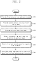
- FIG. 2 is a flowchart showing a method for measuring a depth profile of a particle beam 12 according to the inventive concept
- FIG. 3 shows an eardrum and a cochlea respectively in the middle ear and the internal ear of the auditory organ of FIG. 1 ;
- FIGS. 4A and 4B show methods of detecting, by the first sensor of FIG. 1 , eardrum vibration.
- exemplary embodiments are described herein with reference to cross-sectional views and/or plane views that are idealized exemplary illustrations.
- the dimensions of layers and regions are exaggerated for clarity of illustration. Accordingly, variations from the shapes of the illustrations as a result, for example, of manufacturing techniques and/or tolerances, are to be expected.
- exemplary embodiments should not be construed as limited to the shapes of regions illustrated herein but are to include deviations in shapes that result, for example, from manufacturing.
- the regions illustrated in the figures are schematic in nature and their shapes are not intended to illustrate the precise shape of a region and are not intended to limit the scope of example embodiments.
- FIG. 1 shows a device 100 for measuring a depth profile of a particle beam of the inventive concept.
- the device 100 for measuring a depth profile of a particle beam may include a particle beam source 10 , a hodoscope 20 , first sensors 32 , second sensors 34 , a signal amplifier 40 , a signal processor 50 , and a signal analyzer 60 .
- the particle beam source 10 may generate a particle beam 12 .
- the particle beam 12 may be provided into the head 2 of a human body.
- the particle beam 12 may include a proton beam.
- the particle beam source 10 may include a proton generator.
- the particle beam source 10 may include a laser device for generating a laser light, and a target for generating a particle beam by the laser light.
- the target may include a carbon component such as graphene, graphite, or a carbon nanotube, and the inventive concept is not limited thereto and may be variously embodied and practiced.
- the hodoscope 20 may be disposed between the particle beam source 10 and the head 2 .
- the hodoscope 20 may detect an incidence time, dose and/or incidence direction of the particle beam 12 .
- the particle beam 12 may pass the hodoscope 12 and then be provided into a tumor 4 in the head 2 .
- the particle beam 12 may have a Bragg peak position and/or point 6 in the tumor 4 and generate an acoustic signal 14 .
- the acoustic signal 14 may be provided into auditory organs 8 in the head 2 .
- the acoustic signal 14 may have an audible frequency of about 16 Hz to about 20 KHz.
- the particle beam 12 may generate the acoustic signal 14 of a radio frequency above 20 KHz, which is higher than the audible frequency.
- the first sensors 32 may be provided in the head 2 of the human body. According to an embodiment, the first sensors 32 may be disposed in a first direction x in the auditory organs 8 of the head 2 . For example, the first sensors 32 may be provided in the opposite earholes of the head 2 . The first sensors 32 may sense the acoustic signal 14 to generate a first sensing signal 31 . The first sensing signal 31 may provide information about the Bragg peak position 6 for the first direction x.
- the first sensor 32 may include a piezoelectric sensor, optical sensor, photodiode, or optical fiber acoustic sensor.
- the second sensors 34 may be disposed in the head 2 of the human body in a second direction y.
- the second sensor 34 may be disposed on the top of the head 2 and in the mouth 9 .
- the second sensors 34 may sense the acoustic signal 14 to generate second sensing signals 33 .
- the second sensing signals 33 may provide information about the Bragg peak position 6 for the second direction y.
- the second sensor 34 may include a piezoelectric sensor.
- the signal amplifier 40 may be connected to the first and second sensors 32 and 34 .
- the signal amplifier 40 may amplify the first and second sensing signals 31 and 33 from the first and second sensors 32 and 34 .
- the signal processor 50 may be connected to the hodoscope 20 and the signal amplifier 40 . According to an example, the signal processor 50 may process information from the particle beam 12 and the acoustic signal 14 . The signal processor 50 may receive detection signals from the particle beam 12 , and the first and second sensing signals 31 and 33 . The signal processor 50 may determine the dose and incidence direction of the particle beam 12 . The signal processor 50 may determine a frequency, phase, and strength of each of the first and second sensing signals 31 and 33 .
- the signal analyzer 60 may be connected to the signal processor 50 .
- the signal analyzer 60 may calculate and/or determine the Bragg peak position 6 of the particle beam 12 for the first and second directions x and y by using the incidence direction of the particle beam 12 and a phase difference between the first and second sensing signals 31 and 33 .
- the signal processor 60 may determine an absorption dose of the particle beam 12 by using the strengths of the first and second sensing signals 31 and 33 .
- the signal processor 50 and the signal analyzer 60 may be configured from one computer. A method for calculating the Bragg peak position 6 , the depth profile of the particle beam 12 , and/or the absorption dose of the particle beam 12 by the signal processor 50 and the signal analyzer 60 will be described in detail in the following.
- a depth profile measuring method of a device 100 for measuring a depth profile of the particle beam 12 configured in this way will be described in detail.
- FIG. 2 shows a method of measuring a depth profile of the particle beam 12 according to the inventive concept.
- the depth profile measuring method of the particle beam 12 may include providing the first sensors 32 in the auditory organs 8 of a human body (operation S 10 ), providing the second sensors 34 in the mouth 9 and the top of the head (operation S 20 ), providing the particle beam 12 into the head 2 of the human body (operation S 30 ), detecting an incidence time and traveling direction of the particle beam 12 (operation S 40 ), obtaining the first and second sensing signals 31 and 33 (operation S 50 ), and calculating the Bragg peak position 6 of the particle beam 12 in the head 2 from the first and second sensing signals 31 and 33 (operation S 50 ).
- the first sensors 32 are provided in the auditory organs 8 of both sides of the head 2 (operation S 10 ).
- the first sensors 32 may be provided in the auditory organs 8 by an operator and/or robot in the first direction x.
- the signal processor 50 and/or the signal analyzer 60 may detect a first distance d 1 between the first sensors 32 .
- the first distance d 1 may be detected through short-range communication such as Bluetooth.
- each of the auditory organs 8 may be divided into an external ear, a middle ear, and an internal ear in a depth direction.
- the external ear may be defined as a part closed to the ear protruding out from the head, the internal ear as a part farthest away from the ear, and the middle ear as a part connecting between the external and internal ears.
- FIG. 3 shows respectively an eardrum 92 and the cochlea 94 in the middle ear 82 and the internal ear 84 of the auditory organ of FIG. 1 .
- the eardrum 92 is disposed in the middle ear 82 and the cochlea 94 may be disposed in the internal ear 84 .
- the eardrum 92 may have a thin plate form.
- the eardrum 92 may convert a sound outside the auditory organ 8 to an external acoustic vibration, and deliver the external acoustic vibration to the brain in the head 2 through the cochlea 94 .
- the cochlea 94 may be filled with a gas and/or fluid.
- the eardrum 92 may convert the acoustic signal 14 in the cochlea 94 to an internal sound, and discharge the internal sound outside the auditory organ 8 .
- the acoustic signal 14 and the internal sound may correspond to electromagnetic energy.
- both the acoustic sound 14 and the internal sound will be described as the acoustic signal 14 .
- each of the first and second sensors 32 and 34 may be provided in the middle ear 82 .
- the second sensors 34 are provided on the top 7 of the head and in the mouth 9 (operation S 20 ).
- the second sensors 34 may be provided on the top 7 and/or crown of the head and in the mouth 9 by an operator and/or robot in the second direction y.
- the signal processor 50 and/or the signal analyzer 60 may detect a second distance d 2 between the second sensors 34 .
- the second distance d 2 may be detected through short-range communication such as Bluetooth.
- the particle beam source 10 provides the particle beam 12 into the head 2 through the hodoscope 20 (operation S 30 ).
- the particle beam 12 may be incident in a third direction (not shown) with an arbitrary dose.
- the hodoscope 20 detects the dose and traveling direction of the particle beam (operation S 40 ).
- the hodoscope 20 may transmit a detection signal of the particle beam 12 to the signal analyzer 50 .
- the signal processor 50 may control the particle beam 10 .
- the particle beam 12 in the head 2 may be provided into the tumor 4 .
- the particle beam 12 may be absorbed at the Bragg peak position 6 in the tumor 4 and generate the acoustic signal 14 .
- the acoustic signal 14 may be delivered to the auditory organs 8 .
- the first and second sensors 32 and 34 sense the acoustic signal 14 (operation S 50 ).
- the first sensors 32 may sense the acoustic signal 14 at the eardrum 92 in the middle ear 82 .
- the sensing method of the acoustic signal 14 is as the following.
- FIGS. 4A and 4B show a method of sensing the acoustic signal 14 at the eardrum 92 by the first sensor 32 of FIG. 1 .
- the first sensor 32 of a piezoelectric element may directly sense the acoustic signal 14 at the eardrum.
- the eardrum 92 may provide the acoustic signal 14 to the first sensor 32 through the air in an earhole.
- the first sensor 32 may sense the vibration of the eardrum 92 with light 90 .
- the second sensor 34 may sense the vibration of the eardrum 92 with the same light 90 as that for the first sensor 32 .
- the first sensor 32 may include an optical source and an optical sensor.
- the optical source may provide the light 90 to the eardrum 92 .
- the optical sensor may sense the light 90 reflected by the eardrum 92 .
- the second sensors 34 may directly sense the acoustic signal 14 on the top 7 of the head and in the mouth 9 .
- the signal analyzer 60 analyzes the sensed first and second sensing signals 31 and 33 and calculates the depth profile of the particle beam 12 .
- the signal analyzer 60 may calculate the Bragg peak position 6 in the first direction x by using the first sensing signal 31 .
- the signal analyzer 60 may obtain the Bragg peak position 6 in the first direction x from the first sensing signal 31 .
- the signal analyzer 60 may obtain the Bragg peak position 6 within the first distance d 1 .
- the signal analyzer 60 may calculate the Bragg peak position 6 in the second direction y by using the second sensing signal 33 .
- the signal analyzer 60 may obtain the Bragg peak position 6 for the second direction y from the second sensing signal 33 .
- the signal analyzer 60 may obtain the Bragg peak position 6 within the second distance d 2 .
- the method of measuring a depth profile of a particle beam according to the inventive concept may effectively detect acoustic signals and calculate a Bragg peak position of a particle beam for first and second directions by using the acoustic signals.
Landscapes
- Health & Medical Sciences (AREA)
- Life Sciences & Earth Sciences (AREA)
- Engineering & Computer Science (AREA)
- Biomedical Technology (AREA)
- High Energy & Nuclear Physics (AREA)
- Molecular Biology (AREA)
- Spectroscopy & Molecular Physics (AREA)
- Physics & Mathematics (AREA)
- General Physics & Mathematics (AREA)
- Pathology (AREA)
- Nuclear Medicine, Radiotherapy & Molecular Imaging (AREA)
- Radiology & Medical Imaging (AREA)
- Animal Behavior & Ethology (AREA)
- General Health & Medical Sciences (AREA)
- Public Health (AREA)
- Veterinary Medicine (AREA)
- Ultra Sonic Daignosis Equipment (AREA)
Abstract
Description
Claims (12)
Applications Claiming Priority (4)
| Application Number | Priority Date | Filing Date | Title |
|---|---|---|---|
| KR10-2016-0165324 | 2016-12-06 | ||
| KR20160165324 | 2016-12-06 | ||
| KR10-2017-0153300 | 2017-11-16 | ||
| KR1020170153300A KR102450680B1 (en) | 2016-12-06 | 2017-11-16 | method for measuring depth profile of particle beam |
Publications (2)
| Publication Number | Publication Date |
|---|---|
| US20180154182A1 US20180154182A1 (en) | 2018-06-07 |
| US10695584B2 true US10695584B2 (en) | 2020-06-30 |
Family
ID=62239897
Family Applications (1)
| Application Number | Title | Priority Date | Filing Date |
|---|---|---|---|
| US15/833,706 Expired - Fee Related US10695584B2 (en) | 2016-12-06 | 2017-12-06 | Method for measuring depth profile of particle beam using acoustic signals generated by the particle beam |
Country Status (1)
| Country | Link |
|---|---|
| US (1) | US10695584B2 (en) |
Families Citing this family (2)
| Publication number | Priority date | Publication date | Assignee | Title |
|---|---|---|---|---|
| US11607566B1 (en) * | 2019-11-27 | 2023-03-21 | Brett K Nelson | Automated 3D dosimetry |
| CN111999760B (en) * | 2020-09-01 | 2025-08-12 | 上海市质子重离子临床技术研发中心 | Heavy ion Bragg peak on-line detection method and detection system thereof |
Citations (5)
| Publication number | Priority date | Publication date | Assignee | Title |
|---|---|---|---|---|
| US20130218009A1 (en) * | 2008-05-22 | 2013-08-22 | Vladimir Balakin | Charged particle therapy patient constraint apparatus and method of use thereof |
| US20130261369A1 (en) | 2012-03-30 | 2013-10-03 | Electronics And Telecommunications Research Institute | Target for generating ion and treatment apparatus using the same |
| US20140061493A1 (en) | 2011-02-04 | 2014-03-06 | Damien Prieels | Apparatus For Particle Therapy Verification |
| US8835870B2 (en) | 2012-01-09 | 2014-09-16 | Electronics And Telecommunications Research Institute | Targets for generating ions and treatment apparatuses using the targets |
| US20170165504A1 (en) * | 2014-07-18 | 2017-06-15 | Ludwig-Maximilians-Universität München | A Method and Apparatus for Determining an Energy Deposition of an Ion Beam |
-
2017
- 2017-12-06 US US15/833,706 patent/US10695584B2/en not_active Expired - Fee Related
Patent Citations (5)
| Publication number | Priority date | Publication date | Assignee | Title |
|---|---|---|---|---|
| US20130218009A1 (en) * | 2008-05-22 | 2013-08-22 | Vladimir Balakin | Charged particle therapy patient constraint apparatus and method of use thereof |
| US20140061493A1 (en) | 2011-02-04 | 2014-03-06 | Damien Prieels | Apparatus For Particle Therapy Verification |
| US8835870B2 (en) | 2012-01-09 | 2014-09-16 | Electronics And Telecommunications Research Institute | Targets for generating ions and treatment apparatuses using the targets |
| US20130261369A1 (en) | 2012-03-30 | 2013-10-03 | Electronics And Telecommunications Research Institute | Target for generating ion and treatment apparatus using the same |
| US20170165504A1 (en) * | 2014-07-18 | 2017-06-15 | Ludwig-Maximilians-Universität München | A Method and Apparatus for Determining an Energy Deposition of an Ion Beam |
Non-Patent Citations (1)
| Title |
|---|
| A.I. Kalinichenko et al., "Radiation-Acoustic Monitoring of Therapeutic Beam", Proceedings of the 2003 Particle Accelerator Conference, 2003, pp. 1080-1082, IEEE. |
Also Published As
| Publication number | Publication date |
|---|---|
| US20180154182A1 (en) | 2018-06-07 |
Similar Documents
| Publication | Publication Date | Title |
|---|---|---|
| US20240252846A1 (en) | Ultrasound autofocusing using reflections | |
| EP3723856B1 (en) | Control of exogenous agent characteristics in microbubble-mediated ultrasound procedures | |
| EP3723617B1 (en) | Phased array calibration for geometry and aberration correction | |
| US7391849B2 (en) | Energy monitoring target for x-ray dose-rate control | |
| TWI520758B (en) | Neutron capture therapy apparatus and method for measuring the neutron beam | |
| WO2011148486A1 (en) | Particle beam irradiation system and control method for particle beam irradiation system | |
| JP2020534077A (en) | Focus cavitation signal measurement | |
| US9873003B2 (en) | X-ray positioning apparatus, X-ray positioning method, and attentional image photographing method | |
| US10695584B2 (en) | Method for measuring depth profile of particle beam using acoustic signals generated by the particle beam | |
| JP6144114B2 (en) | Neutron capture therapy device and irradiation object position correction method | |
| US10391333B2 (en) | Treatment apparatus using proton and ultrasound and method of treating cancer using the same | |
| CN108535696B (en) | Proton Bragg peak on-line positioning method and monitoring device | |
| KR101678681B1 (en) | Device for radiotherapy and method for quality assurance for the same | |
| JP4288351B2 (en) | System for simultaneous measurement of target organ and dose distribution during irradiation | |
| Ghesquière-Diérickx et al. | Investigation of suitable detection angles for carbon-ion radiotherapy monitoring in depth by means of secondary-ion tracking | |
| KR102450680B1 (en) | method for measuring depth profile of particle beam | |
| US10434336B2 (en) | Ion therapy device and therapy method using ion beam | |
| JP7169830B2 (en) | Neutron capture therapy system | |
| JP6873465B2 (en) | How to operate the electron beam irradiator and the electron beam irradiator | |
| WO2022141399A1 (en) | Focus verification method, plan verification method, system, apparatus, and storage medium | |
| US12599783B2 (en) | Quality assurance for a radiotherapy device | |
| US10026516B2 (en) | Collimator apparatus, radiation system, and method for controlling collimators | |
| JPH1052509A (en) | Medical charged particle beam device | |
| KR102829676B1 (en) | Control device for ultrasonic transducer module equipped with ultrasonic focal point indicator and driving method thereof | |
| CN120000967B (en) | Automatic control device, method and system for ray emission |
Legal Events
| Date | Code | Title | Description |
|---|---|---|---|
| FEPP | Fee payment procedure |
Free format text: ENTITY STATUS SET TO UNDISCOUNTED (ORIGINAL EVENT CODE: BIG.); ENTITY STATUS OF PATENT OWNER: SMALL ENTITY |
|
| AS | Assignment |
Owner name: ELECTRONICS AND TELECOMMUNICATIONS RESEARCH INSTITUTE, KOREA, REPUBLIC OF Free format text: ASSIGNMENT OF ASSIGNORS INTEREST;ASSIGNORS:SHIN, DONG-HO;JUNG, MOON YOUN;KIM, SEUNGHWAN;REEL/FRAME:044339/0559 Effective date: 20171124 Owner name: ELECTRONICS AND TELECOMMUNICATIONS RESEARCH INSTIT Free format text: ASSIGNMENT OF ASSIGNORS INTEREST;ASSIGNORS:SHIN, DONG-HO;JUNG, MOON YOUN;KIM, SEUNGHWAN;REEL/FRAME:044339/0559 Effective date: 20171124 |
|
| FEPP | Fee payment procedure |
Free format text: ENTITY STATUS SET TO SMALL (ORIGINAL EVENT CODE: SMAL); ENTITY STATUS OF PATENT OWNER: SMALL ENTITY |
|
| STPP | Information on status: patent application and granting procedure in general |
Free format text: DOCKETED NEW CASE - READY FOR EXAMINATION |
|
| STPP | Information on status: patent application and granting procedure in general |
Free format text: NON FINAL ACTION MAILED |
|
| STPP | Information on status: patent application and granting procedure in general |
Free format text: RESPONSE TO NON-FINAL OFFICE ACTION ENTERED AND FORWARDED TO EXAMINER |
|
| STCF | Information on status: patent grant |
Free format text: PATENTED CASE |
|
| FEPP | Fee payment procedure |
Free format text: MAINTENANCE FEE REMINDER MAILED (ORIGINAL EVENT CODE: REM.); ENTITY STATUS OF PATENT OWNER: SMALL ENTITY |
|
| LAPS | Lapse for failure to pay maintenance fees |
Free format text: PATENT EXPIRED FOR FAILURE TO PAY MAINTENANCE FEES (ORIGINAL EVENT CODE: EXP.); ENTITY STATUS OF PATENT OWNER: SMALL ENTITY |
|
| STCH | Information on status: patent discontinuation |
Free format text: PATENT EXPIRED DUE TO NONPAYMENT OF MAINTENANCE FEES UNDER 37 CFR 1.362 |
|
| FP | Lapsed due to failure to pay maintenance fee |
Effective date: 20240630 |