US10695111B2 - Modular bone plate and connector piece for a modular bone plate - Google Patents
Modular bone plate and connector piece for a modular bone plate Download PDFInfo
- Publication number
- US10695111B2 US10695111B2 US15/876,526 US201815876526A US10695111B2 US 10695111 B2 US10695111 B2 US 10695111B2 US 201815876526 A US201815876526 A US 201815876526A US 10695111 B2 US10695111 B2 US 10695111B2
- Authority
- US
- United States
- Prior art keywords
- connector piece
- connection portion
- recess
- female
- slot
- Prior art date
- Legal status (The legal status is an assumption and is not a legal conclusion. Google has not performed a legal analysis and makes no representation as to the accuracy of the status listed.)
- Active, expires
Links
- 210000000988 bone and bone Anatomy 0.000 title claims abstract description 95
- 210000002758 humerus Anatomy 0.000 claims description 6
- 238000010276 construction Methods 0.000 claims description 4
- 230000007423 decrease Effects 0.000 claims description 4
- 238000004873 anchoring Methods 0.000 description 7
- 238000004891 communication Methods 0.000 description 3
- 239000000463 material Substances 0.000 description 3
- 239000004696 Poly ether ether ketone Substances 0.000 description 2
- 238000011161 development Methods 0.000 description 2
- 230000018109 developmental process Effects 0.000 description 2
- 239000007943 implant Substances 0.000 description 2
- 229910001000 nickel titanium Inorganic materials 0.000 description 2
- 229920002530 polyetherether ketone Polymers 0.000 description 2
- 208000020084 Bone disease Diseases 0.000 description 1
- RTAQQCXQSZGOHL-UHFFFAOYSA-N Titanium Chemical compound [Ti] RTAQQCXQSZGOHL-UHFFFAOYSA-N 0.000 description 1
- 229910045601 alloy Inorganic materials 0.000 description 1
- 239000000956 alloy Substances 0.000 description 1
- 239000000560 biocompatible material Substances 0.000 description 1
- 239000002639 bone cement Substances 0.000 description 1
- KHYBPSFKEHXSLX-UHFFFAOYSA-N iminotitanium Chemical compound [Ti]=N KHYBPSFKEHXSLX-UHFFFAOYSA-N 0.000 description 1
- 238000004519 manufacturing process Methods 0.000 description 1
- 239000002184 metal Substances 0.000 description 1
- 229910052751 metal Inorganic materials 0.000 description 1
- 229910001092 metal group alloy Inorganic materials 0.000 description 1
- 230000004048 modification Effects 0.000 description 1
- 238000012986 modification Methods 0.000 description 1
- HLXZNVUGXRDIFK-UHFFFAOYSA-N nickel titanium Chemical compound [Ti].[Ti].[Ti].[Ti].[Ti].[Ti].[Ti].[Ti].[Ti].[Ti].[Ti].[Ni].[Ni].[Ni].[Ni].[Ni].[Ni].[Ni].[Ni].[Ni].[Ni].[Ni].[Ni].[Ni].[Ni] HLXZNVUGXRDIFK-UHFFFAOYSA-N 0.000 description 1
- 239000004033 plastic Substances 0.000 description 1
- 230000000087 stabilizing effect Effects 0.000 description 1
- 239000010935 stainless steel Substances 0.000 description 1
- 229910001220 stainless steel Inorganic materials 0.000 description 1
- 239000010936 titanium Substances 0.000 description 1
- 229910052719 titanium Inorganic materials 0.000 description 1
- 210000000707 wrist Anatomy 0.000 description 1
Images


Classifications
-
- A—HUMAN NECESSITIES
- A61—MEDICAL OR VETERINARY SCIENCE; HYGIENE
- A61B—DIAGNOSIS; SURGERY; IDENTIFICATION
- A61B17/00—Surgical instruments, devices or methods, e.g. tourniquets
- A61B17/56—Surgical instruments or methods for treatment of bones or joints; Devices specially adapted therefor
- A61B17/58—Surgical instruments or methods for treatment of bones or joints; Devices specially adapted therefor for osteosynthesis, e.g. bone plates, screws, setting implements or the like
- A61B17/68—Internal fixation devices, including fasteners and spinal fixators, even if a part thereof projects from the skin
- A61B17/80—Cortical plates, i.e. bone plates; Instruments for holding or positioning cortical plates, or for compressing bones attached to cortical plates
- A61B17/8023—Variable length plates adjustable in both directions
-
- A—HUMAN NECESSITIES
- A61—MEDICAL OR VETERINARY SCIENCE; HYGIENE
- A61B—DIAGNOSIS; SURGERY; IDENTIFICATION
- A61B17/00—Surgical instruments, devices or methods, e.g. tourniquets
- A61B17/56—Surgical instruments or methods for treatment of bones or joints; Devices specially adapted therefor
- A61B17/58—Surgical instruments or methods for treatment of bones or joints; Devices specially adapted therefor for osteosynthesis, e.g. bone plates, screws, setting implements or the like
- A61B17/68—Internal fixation devices, including fasteners and spinal fixators, even if a part thereof projects from the skin
- A61B17/70—Spinal positioners or stabilisers ; Bone stabilisers comprising fluid filler in an implant
- A61B17/7059—Cortical plates
-
- A—HUMAN NECESSITIES
- A61—MEDICAL OR VETERINARY SCIENCE; HYGIENE
- A61B—DIAGNOSIS; SURGERY; IDENTIFICATION
- A61B17/00—Surgical instruments, devices or methods, e.g. tourniquets
- A61B17/56—Surgical instruments or methods for treatment of bones or joints; Devices specially adapted therefor
- A61B17/58—Surgical instruments or methods for treatment of bones or joints; Devices specially adapted therefor for osteosynthesis, e.g. bone plates, screws, setting implements or the like
- A61B17/68—Internal fixation devices, including fasteners and spinal fixators, even if a part thereof projects from the skin
- A61B17/80—Cortical plates, i.e. bone plates; Instruments for holding or positioning cortical plates, or for compressing bones attached to cortical plates
-
- A—HUMAN NECESSITIES
- A61—MEDICAL OR VETERINARY SCIENCE; HYGIENE
- A61B—DIAGNOSIS; SURGERY; IDENTIFICATION
- A61B17/00—Surgical instruments, devices or methods, e.g. tourniquets
- A61B17/56—Surgical instruments or methods for treatment of bones or joints; Devices specially adapted therefor
- A61B17/58—Surgical instruments or methods for treatment of bones or joints; Devices specially adapted therefor for osteosynthesis, e.g. bone plates, screws, setting implements or the like
- A61B17/68—Internal fixation devices, including fasteners and spinal fixators, even if a part thereof projects from the skin
- A61B17/70—Spinal positioners or stabilisers ; Bone stabilisers comprising fluid filler in an implant
-
- A—HUMAN NECESSITIES
- A61—MEDICAL OR VETERINARY SCIENCE; HYGIENE
- A61B—DIAGNOSIS; SURGERY; IDENTIFICATION
- A61B17/00—Surgical instruments, devices or methods, e.g. tourniquets
- A61B17/56—Surgical instruments or methods for treatment of bones or joints; Devices specially adapted therefor
- A61B17/58—Surgical instruments or methods for treatment of bones or joints; Devices specially adapted therefor for osteosynthesis, e.g. bone plates, screws, setting implements or the like
- A61B17/68—Internal fixation devices, including fasteners and spinal fixators, even if a part thereof projects from the skin
- A61B17/80—Cortical plates, i.e. bone plates; Instruments for holding or positioning cortical plates, or for compressing bones attached to cortical plates
- A61B17/8033—Cortical plates, i.e. bone plates; Instruments for holding or positioning cortical plates, or for compressing bones attached to cortical plates having indirect contact with screw heads, or having contact with screw heads maintained with the aid of additional components, e.g. nuts, wedges or head covers
- A61B17/8042—Cortical plates, i.e. bone plates; Instruments for holding or positioning cortical plates, or for compressing bones attached to cortical plates having indirect contact with screw heads, or having contact with screw heads maintained with the aid of additional components, e.g. nuts, wedges or head covers the additional component being a cover over the screw head
-
- A—HUMAN NECESSITIES
- A61—MEDICAL OR VETERINARY SCIENCE; HYGIENE
- A61B—DIAGNOSIS; SURGERY; IDENTIFICATION
- A61B17/00—Surgical instruments, devices or methods, e.g. tourniquets
- A61B17/56—Surgical instruments or methods for treatment of bones or joints; Devices specially adapted therefor
- A61B17/58—Surgical instruments or methods for treatment of bones or joints; Devices specially adapted therefor for osteosynthesis, e.g. bone plates, screws, setting implements or the like
- A61B17/68—Internal fixation devices, including fasteners and spinal fixators, even if a part thereof projects from the skin
- A61B17/80—Cortical plates, i.e. bone plates; Instruments for holding or positioning cortical plates, or for compressing bones attached to cortical plates
- A61B17/8061—Cortical plates, i.e. bone plates; Instruments for holding or positioning cortical plates, or for compressing bones attached to cortical plates specially adapted for particular bones
-
- A—HUMAN NECESSITIES
- A61—MEDICAL OR VETERINARY SCIENCE; HYGIENE
- A61B—DIAGNOSIS; SURGERY; IDENTIFICATION
- A61B17/00—Surgical instruments, devices or methods, e.g. tourniquets
- A61B17/56—Surgical instruments or methods for treatment of bones or joints; Devices specially adapted therefor
- A61B17/58—Surgical instruments or methods for treatment of bones or joints; Devices specially adapted therefor for osteosynthesis, e.g. bone plates, screws, setting implements or the like
- A61B17/68—Internal fixation devices, including fasteners and spinal fixators, even if a part thereof projects from the skin
- A61B17/84—Fasteners therefor or fasteners being internal fixation devices
- A61B17/86—Pins or screws or threaded wires; nuts therefor
Definitions
- the invention relates to a modular bone plate and to a connector piece for a modular bone plate.
- U.S. Pat. No. 5,484,439 describes a modular implant for use in stabilizing femoral bone disorders.
- the implant has an upper side plate with a widened head and an angled barrel and a lower side plate adapted to be engaged with the upper side plate in a tongue and groove configuration.
- the object underlying the invention is to provide an improved modular bone plate that can be realized for various clinical applications and that is easy to assemble while providing a strong and durable construct.
- the bone plate according to the invention comprises at least two members each having a top surface and a bottom surface and that can be connected together.
- the members include a male connection portion with a single hole extending from the top surface to the bottom surface and a female connection portion with a single hole extending from the top surface to the bottom surface.
- the male connection portion is insertable into the female connection portion so that the holes overlap and wherein an anchor or a plug member is insertable into the holes when they overlap.
- the engagement portion of the male portion is relatively short. This makes the adjustment and engagement step easy to perform.
- the modular bone plate may be designed pivotable such that an angle between the members to be connected can be selected.
- the members may be locked with respect to each other in the angled configuration.
- Locking and non-locking screws may be used with the modular bone plate.
- the locking screws make use of a locking cap that is screwed into the hole. This renders the construct more stable and increases the stiffness.
- the plate portions can be clamped together also without screws using a plug member.
- FIG. 1 a shows a perspective view of a modular bone plate assembly according to a first embodiment
- FIG. 1 b shows an exploded view of the modular bone plate assembly according to the first embodiment
- FIG. 1 c shows a cross sectional perspective view of the modular bone plate assembly to the first embodiment
- FIG. 1 d shows a cross sectional view of the bone plate assembly according to the first embodiment
- FIG. 2 a shows a perspective view of a ball locking cap from the top
- FIG. 2 b shows a perspective view of the ball locking cap from the bottom
- FIG. 3 a shows a perspective view of a male end piece of the modular bone plate according to the first embodiment
- FIG. 3 b shows a perspective view of a female end piece according to a first embodiment
- FIG. 4 shows a perspective view of a female/male connector piece according to a first embodiment
- FIG. 5 a shows a top view of a modular bone plate assembly in a second angled embodiment that has an angled configuration
- FIG. 5 b shows a cross sectional top view of the modular bone plate assembly according to the second embodiment
- FIG. 6 shows a cross sectional top view of an angled male/female connector piece in a second embodiment
- FIG. 7 a shows a perspective view of a modular bone plate system according to a third embodiment
- FIG. 7 b shows a side view of the modular bone plate assembly according to the third embodiment
- FIG. 7 c shows a cross sectional side view of the modular bone plate assembly according to the third embodiment
- FIG. 7 d shows a cross sectional perspective view of the modular bone plate assembly according to the third embodiment
- FIG. 7 e shows an exploded view of the modular bone plate assembly according to the third embodiment
- FIG. 8 a shows a perspective view of the female/male connector piece (4.5 mm to 2.5 mm) according to a third embodiment
- FIG. 8 b shows a side view of the female/male connector piece (4.5 mm to 2.5 mm) according to a third embodiment
- FIG. 9 a shows a perspective view of the female/male connector piece (3.5 mm to 2.5 mm) according to a fourth embodiment
- FIG. 9 b shows a side view of the female/male connector piece (3.5 mm to 2.5 mm) according to a fourth embodiment
- FIG. 10 a shows a perspective view of a modular bone plate assembly according to a fourth embodiment
- FIG. 10 b shows a side view of the modular borne plate assembly according to the fourth embodiment
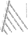
- FIGS. 11 a -11 e show perspective views of a humerus expandable plate according to a fifth embodiment
- FIGS. 12 a -12 e show exploded views of the humerus expandable plate according to the fifth embodiment
- FIGS. 13 a -13 e show perspective top views of the humerus expandable plate according to the fifth embodiment
- FIGS. 14 a -14 e show perspective bottom views of the humerus expandable plate according to the fifth embodiment
- FIG. 15 shows a top view of a modular hard angle bone plate according to a sixth embodiment
- FIGS. 16 a -16 i show top views of hard angle connector pieces having angles from 0° to 90°;
- FIGS. 17 a -17 i show perspective views of hard angle connector pieces shown in FIG. 16 a - i;
- FIG. 18 a shows a perspective view of a female/male connector piece according to a fifth embodiment (angle 45°);
- FIG. 18 b shows a cross sectional top view of the female/male connector piece according to the fifth embodiment (angle 45°);
- FIG. 19 a shows a perspective view of a female/male connector piece in a sixth embodiment (angle 90°);
- FIG. 19 b shows a cross sectional top view of the female/male connector piece in the sixth embodiment (angle 90°);
- FIGS. 20 a -20 e show perspective views of a modular T-plate according to a seventh embodiment
- FIGS. 21 a -21 e show exploded views of the modular T-plate according to the seventh embodiment
- FIGS. 22 a -22 e show perspective views of a modular Y-plate according to an eighth embodiment
- FIGS. 23 a -23 e show exploded views of the modular Y-plate according to the eighth embodiment
- FIGS. 24 a -24 c show perspective front views of a modular bone plate having interchangeable heads according to a ninth embodiment
- FIGS. 25 a -25 c show exploded views of the modular bone plate according to the ninth embodiment
- FIG. 26 a shows a perspective view of a modular bone plate assembly according to a tenth embodiment in a first orientation
- FIG. 26 b shows a perspective view of the modular bone plate assembly according to a tenth embodiment in a second orientation
- FIG. 27 shows a perspective view of a double latch connector according to the second embodiment
- FIG. 28 a shows a perspective view of a female/male connector according to a seventh embodiment in a first orientation
- FIG. 28 b shows a perspective view of the female/male connector according to the seventh embodiment in a second orientation
- FIG. 29 shows a cross sectional side view of the modular bone plate assembly according to the tenth embodiment
- FIG. 30 a shows a perspective view of a modular bone plate according to an eleventh embodiment
- FIG. 30 b shows an exploded view of the modular bone plate according to the eleventh embodiment
- FIG. 30 c shows a cross sectional perspective view of the modular bone plate according to the eleventh embodiment
- FIG. 31 a shows a perspective view of a modular bone plate assembly according to the eleventh embodiment
- FIG. 31 b shows a cross sectional perspective view of the modular bone plate assembly according to the eleventh embodiment
- FIG. 31 c shows an exploded view of the modular bone plate assembly according to the eleventh embodiment.
- FIG. 32 a shows a side view of a modular bone plate assembly according to the twelfth embodiment
- FIG. 32 b shows an exploded view of the modular bone plate assembly according to the twelfth embodiment
- FIG. 32 c shows a perspective view of the modular bone plate assembly according to the twelfth embodiment
- the modular bone plate assembly includes a plate member 1 having a top side 1 a and a bottom side 1 b .
- the modular bone plate 1 comprises a female end piece 2 (see FIG. 3 b ), a male end piece 3 (see FIG. 3 a ) and referring to FIGS. 1 a to 1 d , a plurality of female/male connector pieces 4 (see FIG. 4 ).
- the modular bone plate assembly 1 further comprises bone anchoring elements, for example—bone screws 5 having a threaded shank 51 for anchoring the bone anchoring element 5 in a bone and a substantially ball-shaped head 52 with an engagement structure 55 for engagement with a tool, for example a screwdriver. It is also possible to provide other bone anchors, for example bone nails having a threadless shank or having barbs.
- the bone anchoring element 5 may comprise a through bore hole 54 i.e. a channel (see FIG. 1 c ) for inserting, for example, bone cement.
- a substantially cylindrical insert 6 is provided having an outer thread which is adapted to fit with an inner thread of the female end piece 2 or a female connection portion or female part of the female/male connector piece 4 .
- the outer thread may also fit with an inner thread of the male end piece 3 (not shown) or a male connection portion or male part of the female/male connector piece 4 (not shown).
- the insert functions as a locking cap or locking element for locking the head 52 of the bone screw 5 .
- the male end piece 3 which is substantially formed by a plate comprises a through hole 31
- the female end piece 2 comprises a through hole 21
- the female/male connector piece comprises a first through hole 41 and a second through hole 42 (see FIG. 3 a to 4 ).
- the through hole 31 , the through hole 21 , the through hole 41 and the through hole 42 have to be understood as circumferentially closed openings.
- the female end piece 2 is substantially cylindrical and the hole 21 comprises a portion 22 with an internal thread. Further, the female end piece 2 comprises a recess 23 which is provided in the side wall of the female end piece 2 and is in communication with the hole 21 .
- the recess 23 extends about the half of the circumference of the side wall of a female end piece 2 and is adapted to accommodate the male portion of the female/male connector piece 4 .
- the recess 23 extends from the outside into the hole 21 . Thereby a lug or pocket is formed which is adapted to engage a male portion having a tongue or projection.
- the main body of the male end piece 3 is substantially cylindrical and has an extension 32 to one side adapted to the contour of the recess 23 of the female end piece 2 .
- the extension 32 may be formed as tongue or projection which is adapted to engage a female portion having a recess, a lug or a pocket.
- a portion 33 of the hole 31 of the male end piece 3 is beveled and therefore conical on the top side.
- a spherical bottom seat 34 is provided for accommodating the head 52 of the bone screw 5 .
- the female/male connector piece 4 is an integral combination of the male end piece 3 and the female end piece 2 connected by a middle portion 43 .
- the female connection portion of the female/male connector piece 4 hereby comprises a through hole 41 having an inner thread 46 and a recess 45 extending about the half of the circumference of the sidewall of the female connection portion of the female/male connector piece 4 .
- the recess 45 is in communication with the hole 41 .
- the male connection portion of the female/male connector piece 4 is formed by a lug portion 44 having a through hole 42 in its middle.
- the hole 42 has a circumferential beveled portion 47 as the beveled portion 33 of the male end piece 3 and a spherical bottom seat 47 a as the spherical bottom seat 34 of the male end piece 3 .
- the recess 23 of the female end piece 2 or the recess 45 of the female/male connector piece 4 serves for accommodating the male end piece 3 or the male connection portion of the female/male connector piece 4 such that in an assembled state the respective holes of male and female connection portions overlap.
- the extended side 32 of the male end piece 3 is adapted to fit into the recess 23 of the female end piece or the recess 45 of the female/male connector piece.
- the portion 32 of the male end piece 3 or the male portion 44 of the female/male connector piece 4 serves as a tongue portion 32 , 44 and the recess 23 of the female end piece 3 or the recess 45 of the female/male connector piece 4 serves as a lug portion 23 , 45 , respectively.
- the male portion When the male portion is inserted into the female portion, it forms a seat for the ball-shaped head 52 of the bone screw 5 that allows orientation of the bone screw 5 at an angle with respect to the straight position, as shown for example in FIG. 1 a.
- FIG. 1 b and FIG. 1 c referring to the modular bone plate assembly 1 , three female/male connector pieces 4 , one female end piece 2 , and one male end piece 3 are connected to each other.
- the loose connection of these parts is locked by the bone anchoring elements 5 .
- the threaded shaft 51 of the bone anchoring element 5 extends through the hole 31 of the male end piece 3 or the hole 42 of the female/male connector piece 4 or through the hole 41 of the female/male connector piece 4 and the hole 42 of a further female/male connector piece 4 or through the hole 42 of the female/male connector piece 4 and the hole 21 of the female end piece 2 .
- the lower area of the screw head 52 thereby contacts the spherical portion 34 of the male end piece 3 or the spherical portion 47 a of the male portion of the female/male connector piece 4 .
- both portions are centered by the bone anchoring element 5 or another locking element (see FIG. 2 a, b ).
- a further possibility to lock the female parts and the male parts to each other is to provide a ball locking cap 7 , as can be seen from FIG. 2 a and FIG. 2 b .
- the ball locking cap 7 comprises an upper threaded portion 71 and a lower rounded substantially spherical portion 72 which is adapted to cooperate with the spherical portions 34 of the male end piece 3 or the spherical portion 47 a of the female/male connector piece 4 .
- the rounded portion 72 thereby substitutes the lower portion of the head 52 of the bone screw 5 and ensures the centering function as described above.
- the ball locking cap 7 further comprises an engagement portion 73 for being engaged by a tool to screw the ball locking cap 7 into the inner thread 22 of the female end piece of the inner thread 46 of the female/male connector piece or the inner thread 22 of the female end piece 2 .
- the modular bone plate has an angled configuration.
- the tongue portion 44 of the female/male connector piece 4 ′ in the second embodiment is identical to the tongue portion 44 of the female/male connector piece 4 in the first embodiment.
- the lug portion 45 ′ which is adapted to accommodate the tongue portion 44 ′ or the male end piece 3 comprises a circular portion 45 a ′ and two straight portions 45 b ′ that include an angle with respect to each other, which is about 40° in this embodiment. Other angles are also suitable here, for example 10°, 90° or 120°.
- the angle between the straight portions 45 b ′ and a middle axis of the female/male connector piece 4 ′ are each 20°. But these two angles may also be different from each other to define a preferred orientation.
- the female/male connector pieces 4 ′ which are connected to each other can be rotated relative to each other in a plane parallel to the surface of the modular bone plate to achieve an angled configuration.
- FIGS. 7 a to 9 b A third embodiment of the modular bone plate assembly will now be described with reference to FIGS. 7 a to 9 b .
- the modular bone plate 1 ′′ is provided in a cascaded form. Referring to FIGS. 7 a to 7 d the modular bone plate 1 ′′ as a whole decreases in thickness from the left side of the Figures towards the right side of the Figures. Only the top surface 1 a ′′ of the modular bone plate 1 ′′ is lowered referring to FIG. 7 a in two steps by means of two inclined portions 431 ′′ of the female/male connector pieces 4 ′′, which can be seen in FIG. 7 e.
- the female/male connector piece 4 ′′ according to the third embodiment differs from the first embodiment in that the middle portion 43 ′′ comprises an inclined portion 431 ′′ which is provided on the top side of the middle portion 43 ′′ and in that the diameters of the two holes provided at the male and female connection portions of the female/male connector piece 4 ′′ differ from each other.
- the female connection portion of the female/male connector piece 4 hereby comprises a through hole 41 ′′ having an inner thread 46 ′′ and a recess 45 ′′ extending about the half of the circumference of the sidewall of the female connection portion of the female/male connector piece 4 ′′.
- the recess 45 ′′ is in communication with the hole 41 ′′.
- the male connection portion of the female/male connector piece 4 ′′ is formed by a lug portion 44 ′′ having a through hole 42 ′′ in its middle.
- the male and female connection portions of the female/male connector piece 4 ′′ may be formed according to the corresponding portions according to the first embodiment.
- the female/male connector pieces 4 ′′ and 4 ′′′ only differ from each other by the dimensions.
- the female/male connector piece 4 ′′ is a 4.5 mm to 3.5 mm connector;
- the female/male connector piece 4 ′′′ is a 3.5 mm to 2.5 mm connector, as can be seen in FIGS. 9 a , 9 b .
- These mm-values refer to the diameter of the holes. Therefore, this bone plate can be used with screws having different shaft diameters and/or head diameters.
- FIGS. 10 a to 10 b A fourth embodiment of the modular bone plate assembly will be described referring to FIGS. 10 a to 10 b .
- the modular bone plate 1 ′′′ according to the fourth embodiment is also provided in a cascaded form.
- the modular bone plate 1 ′′′ decreases in thickness from the center of the bone plate towards either side by means of inclined portions 431 ′′′ corresponding to the inclined portions 431 ′′ according to the third embodiment.
- the plate is a humerus expandable plate 1 ′′′′.
- the length of the modular bone plate 1 ′′′′ can be chosen as desired.
- the modular bone plate 1 ′′′′ comprises a main body having a plurality of holes for connecting the plate to a bone and none (a), one (b), two (c), three (d) or four (e) female/male connector pieces having a middle portion comprising a hole and one male end piece 3 ′′′′.
- the thickness of the main body or of the bone plate may vary or as can be seen from FIG. 14 , the main body may be bent or angled.
- the modular bone plate 1 ′′′′′ is a hard angle construct or fixed angle construct.
- the modular bone plate 1 ′′′′′ is a combination of the pieces shown in FIG. 16 a - i and FIG. 17 a - i is referring to the parts shown in FIG. 16 and FIG. 17 , FIG. 16 a corresponds to FIG. 17 i , FIG. 16 b corresponds to FIG. 17 h , FIG. 16 c corresponds to FIG. 17 g , FIG. 16 d corresponds to FIG. 17 f , FIG. 16 e corresponds to FIG. 17 e , FIG. 16 f corresponds to FIG. 17 d , FIG.
- FIG. 16 g corresponds to FIG. 17 c
- FIG. 16 h corresponds to FIG. 17 b
- FIG. 16 i corresponds to FIG. 17 a
- the angled construction is achieved, as shown in FIGS. 18 to 19 by providing the recess 45 ′′′′ in the female portion into which the male portion is inserted at an angle with respect to the longitudinal axis of the connector pieces.
- FIGS. 16 e ; 17 e The angles 0° ( FIGS. 16 e ; 17 e ), 30° ( FIGS. 16 d, f ; 17 d, f ), 45° ( FIGS. 16 c, g ; 17 c, g ), 60° ( FIGS. 16 b, h ; 17 b, h ) and 90° ( FIGS. 16 a, i ; 17 a, i ) are shown. Other angles are also possible.
- lug-tongue-principle a configuration shown in FIG. 15 is achievable.
- the configuration is locked by bone screws or with ball locking caps as described above.
- the female portion may also have in addition the angled construction according to FIGS.
- FIGS. 18 a, b and 19 a, b show the 900 angle version as shown in FIGS. 16 a, i and 17 a, i.
- FIGS. 20 and 21 A seventh embodiment of the modular bone plate assembly is shown in FIGS. 20 and 21 .
- the bone plate is a T-plate with a T-shaped head, applicable for example, to the wrist.
- the plate as a whole may be constructed in an angled or bent way.
- FIGS. 22 and 23 An eighth embodiment of the modular bone plate assembly is shown in FIGS. 22 and 23 .
- the bone plate is a Y-plate with a Y-shaped head, applicable, for example, to the elbow.
- FIGS. 24 and 25 A ninth embodiment of the modular bone plate assembly will be described with reference to the FIGS. 24 and 25 .
- the only difference referring to the other embodiments is the exchangeable head which can be seen in FIG. 24 a - c for example.
- FIG. 24 a a straight head with six holes
- FIG. 24 b a straight head having four holes
- FIG. 24 c a head having four holes two of which are inclined are shown.
- FIG. 26 a A tenth embodiment of the modular bone plate assembly 10 ′′′ is shown in FIG. 26 a to FIG. 29 .
- the female connecting piece 2 ′ according to a second embodiment comprises the recess 23 ′ and further a second recess 24 ′ which is positioned referring to FIG. 27 above the recess 23 ′ in the conical portion of the female end piece 2 ′.
- the male portion of the female/male connector piece 4 ′′′′′′ according to a seventh embodiment comprises a projection 432 ′′′′′′ which is attached to the middle portion 43 ′′′′′′.
- the projection 432 ′′′′′′ which extends over the whole width of the middle portion 43 ′′′′′′ is adapted to match with the second recess 48 ′′′′′′ of another female/male connector piece 4 ′′′′′′.
- FIGS. 30 to 31 An eleventh embodiment of the modular bone plate 10 ′′′′ and the modular bone plate 100 will be described with reference to FIGS. 30 to 31 .
- the difference referring to the above-mentioned embodiments is that the male portion comprises an internal thread 101 ′′′′ in the hole and the female portion of the female/male connector piece is threadless.
- the connection can be fixed with an ordinary screw 7 ′.
- the plate is also suitable for being used with ordinary bone screws without ball-shaped head.
- the connector piece may also be a longer piece with one or several additional holes and a female and a male portion at the ends.
- a twelfth embodiment of the modular bone plate 10 ′′′′′ will be described with reference to FIGS. 32 a to 32 c .
- the difference to the tenth embodiment is that the projection 432 ′′′′′′′ is attached at the middle portion 43 ′′′′′′′ of a first member such that an upper face of the projection 432 ′′′′′′′ is flush with an upper face of the middle portion 43 ′′′′′′′.
- the second recess 48 ′′′′′′′ is attached to a middle portion 43 ′′′′′′′ of a second member such that it matches with the projection 432 ′′′′′′′.
- a second projection may be attached to the middle portion of the first member such that a lower face of the projection is flush with a lower face of the middle portion.
- the corresponding third recess is provided at the second member.
- the parts of the bone plate are made of biocompatible materials such as biocompatible metal or metal alloys such as titanium, stainless steel, Ni—Ti alloys, for example Nitinol, or biocompatible plastic materials, such as PEEK (polyetheretherketone).
- biocompatible materials such as biocompatible metal or metal alloys such as titanium, stainless steel, Ni—Ti alloys, for example Nitinol, or biocompatible plastic materials, such as PEEK (polyetheretherketone).
- PEEK polyetheretherketone
Abstract
Description
Claims (19)
Priority Applications (1)
| Application Number | Priority Date | Filing Date | Title |
|---|---|---|---|
| US15/876,526 US10695111B2 (en) | 2011-06-17 | 2018-01-22 | Modular bone plate and connector piece for a modular bone plate |
Applications Claiming Priority (4)
| Application Number | Priority Date | Filing Date | Title |
|---|---|---|---|
| US201161497972P | 2011-06-17 | 2011-06-17 | |
| PCT/IB2012/053035 WO2012172517A1 (en) | 2011-06-17 | 2012-06-15 | Modular bone plate and connector piece for a modular bone plate |
| US201314123070A | 2013-11-27 | 2013-11-27 | |
| US15/876,526 US10695111B2 (en) | 2011-06-17 | 2018-01-22 | Modular bone plate and connector piece for a modular bone plate |
Related Parent Applications (2)
| Application Number | Title | Priority Date | Filing Date |
|---|---|---|---|
| US14/123,070 Continuation US9918758B2 (en) | 2011-06-17 | 2012-06-15 | Modular bone plate and connector piece for a modular bone plate |
| PCT/IB2012/053035 Continuation WO2012172517A1 (en) | 2011-06-17 | 2012-06-15 | Modular bone plate and connector piece for a modular bone plate |
Publications (2)
| Publication Number | Publication Date |
|---|---|
| US20180206893A1 US20180206893A1 (en) | 2018-07-26 |
| US10695111B2 true US10695111B2 (en) | 2020-06-30 |
Family
ID=46548526
Family Applications (4)
| Application Number | Title | Priority Date | Filing Date |
|---|---|---|---|
| US14/123,078 Active 2034-04-06 US9956016B2 (en) | 2011-06-17 | 2012-06-15 | Modular bone plate and member of such a modular bone plate |
| US14/123,070 Active 2034-05-10 US9918758B2 (en) | 2011-06-17 | 2012-06-15 | Modular bone plate and connector piece for a modular bone plate |
| US15/828,149 Active US10517656B2 (en) | 2011-06-17 | 2017-11-30 | Modular bone plate and member of such a modular bone plate |
| US15/876,526 Active 2032-07-08 US10695111B2 (en) | 2011-06-17 | 2018-01-22 | Modular bone plate and connector piece for a modular bone plate |
Family Applications Before (3)
| Application Number | Title | Priority Date | Filing Date |
|---|---|---|---|
| US14/123,078 Active 2034-04-06 US9956016B2 (en) | 2011-06-17 | 2012-06-15 | Modular bone plate and member of such a modular bone plate |
| US14/123,070 Active 2034-05-10 US9918758B2 (en) | 2011-06-17 | 2012-06-15 | Modular bone plate and connector piece for a modular bone plate |
| US15/828,149 Active US10517656B2 (en) | 2011-06-17 | 2017-11-30 | Modular bone plate and member of such a modular bone plate |
Country Status (7)
| Country | Link |
|---|---|
| US (4) | US9956016B2 (en) |
| EP (2) | EP2720630B1 (en) |
| JP (2) | JP6001062B2 (en) |
| KR (2) | KR20140037101A (en) |
| CN (2) | CN103635155B (en) |
| ES (2) | ES2616465T3 (en) |
| WO (2) | WO2012172519A1 (en) |
Families Citing this family (27)
| Publication number | Priority date | Publication date | Assignee | Title |
|---|---|---|---|---|
| JP6001062B2 (en) | 2011-06-17 | 2016-10-05 | ビーダーマン・テクノロジーズ・ゲゼルシャフト・ミット・ベシュレンクテル・ハフツング・ウント・コンパニー・コマンディートゲゼルシャフトBiedermann Technologies Gmbh & Co. Kg | Modular bone plate and connecting part for modular bone plate |
| US9421053B2 (en) | 2014-05-08 | 2016-08-23 | Titan Spine, Llc | Implant fixation assemblies having a screw and C-shaped fixation collar |
| CN104224291A (en) * | 2014-05-23 | 2014-12-24 | 上海市浦东新区周浦医院 | Novel combined-type calcaneal-fracture internal fixation steel plate |
| US9839436B2 (en) * | 2014-06-03 | 2017-12-12 | Biomet Manufacturing, Llc | Patient-specific glenoid depth control |
| CN104055571A (en) * | 2014-06-27 | 2014-09-24 | 江苏艾迪尔医疗科技股份有限公司 | Cervical anterior bone plate system |
| CN106794035A (en) | 2014-07-03 | 2017-05-31 | 精密医疗责任有限公司 | With removable diarthrodial hone lamella |
| CN104814781A (en) * | 2015-04-23 | 2015-08-05 | 济南大学 | Modular assembly type bone fracture plate |
| CN104905864A (en) * | 2015-06-19 | 2015-09-16 | 陈伟 | Combined type steel plate for closing fibulas on two sides after fibula section osteotomy |
| US9962192B2 (en) * | 2016-03-17 | 2018-05-08 | Medos International Sarl | Multipoint fixation implants |
| EP3320867B1 (en) | 2016-11-14 | 2021-08-04 | Biedermann Technologies GmbH & Co. KG | Modular bone plate and member of such a modular bone plate |
| CN106859759A (en) * | 2017-03-30 | 2017-06-20 | 中国医学科学院整形外科医院 | A kind of fixed titanium plate of general-purpose operation |
| WO2018227104A1 (en) | 2017-06-08 | 2018-12-13 | Skeletal Dynamics, Llc | Articulated fracture fixation plate assembly and method of use |
| US10932823B2 (en) * | 2017-10-25 | 2021-03-02 | Life Spine, Inc. | Facet plate for implant expulsion prevention and method of installation |
| DE102018101657A1 (en) | 2018-01-25 | 2019-07-25 | Aesculap Ag | Medical bone screw and implant system |
| US10898232B2 (en) | 2018-03-20 | 2021-01-26 | Medos International Sàrl | Multipoint fixation implants and related methods |
| FR3082417B1 (en) * | 2018-06-19 | 2021-06-25 | Arnaud Destainville | MODULAR BONE PLATE MODULE AGENCY TO RECEIVE AN ANCHORING DEVICE, MODULAR BONE PLATE THUS CONSTITUTED AND SYSTEM INCLUDING THE PLATE AND ANCHORING DEVICE |
| FR3082416B1 (en) * | 2018-06-19 | 2021-04-23 | Arnaud Destainville | MODULE AND TERMINAL MODULE FOR MODULAR BONE PLATE, MODULAR BONE PLATE THUS CONSTITUTED AND SYSTEM INCLUDING THE PLATE |
| CN109009379B (en) * | 2018-08-23 | 2023-10-03 | 常州市武进人民医院 | Micro-motion fracture internal fixation system and micro-motion screw for fracture used by same |
| WO2021041634A1 (en) * | 2019-08-27 | 2021-03-04 | Surgical Design Innovations Ii, Llc | Modular digit fixation device and related systems and methods |
| US11426210B2 (en) | 2019-09-25 | 2022-08-30 | Medos International Sàrl | Multipoint angled fixation implants for multiple screws and related methods |
| WO2021160518A1 (en) | 2020-02-14 | 2021-08-19 | Medos International Sarl | Integrated multipoint fixation screw |
| WO2021201318A1 (en) * | 2020-03-31 | 2021-10-07 | 전남대학교산학협력단 | Plate assembly for fixing long bone |
| CN112168323A (en) * | 2020-09-29 | 2021-01-05 | 吉林大学 | Scapula fracture positioning device |
| CN114469299A (en) * | 2020-10-26 | 2022-05-13 | 可成生物科技股份有限公司 | Bone plate connecting kit |
| US11857272B2 (en) * | 2021-05-17 | 2024-01-02 | Si-Restore Llc | Implanted article physical referencing apparatus |
| KR102324320B1 (en) * | 2021-06-18 | 2021-11-11 | (주)포스메디칼 | Implants for surface treatment of bone joints |
| WO2023205448A1 (en) * | 2022-04-22 | 2023-10-26 | The Regents Of The University Of Colorado, A Body Corporate | Orthopedic plate system |
Citations (22)
| Publication number | Priority date | Publication date | Assignee | Title |
|---|---|---|---|---|
| US5484439A (en) * | 1992-09-16 | 1996-01-16 | Alphatec Manufacturing, Inc. | Modular femur fixation device |
| US5520690A (en) | 1995-04-13 | 1996-05-28 | Errico; Joseph P. | Anterior spinal polyaxial locking screw plate assembly |
| US20040074189A1 (en) | 2002-02-06 | 2004-04-22 | Guildo Deschenes | Panels made of interlocked wood pieces |
| US20040102778A1 (en) | 2002-11-19 | 2004-05-27 | Huebner Randall J. | Adjustable bone plates |
| WO2004049903A2 (en) | 2000-02-01 | 2004-06-17 | Hand Innovations, Llc. | Bone fracture fixation systems with both multidirectional and unidirectional stabilization pegs |
| US20060100625A1 (en) | 2004-10-28 | 2006-05-11 | Ralph James D | Adjustable bone plate |
| WO2006102081A1 (en) | 2005-03-17 | 2006-09-28 | Depuy Products, Inc. | Modular fracture fixation plate system |
| US20060229610A1 (en) | 2005-03-21 | 2006-10-12 | Zimmer Spine, Inc. | Variable geometry occipital fixation plate |
| US20060276794A1 (en) * | 2005-05-12 | 2006-12-07 | Stern Joseph D | Revisable anterior cervical plating system |
| US20070276383A1 (en) * | 2006-05-11 | 2007-11-29 | Rayhack L.L.C. | Osteotomy system |
| US20080039847A1 (en) | 2006-08-09 | 2008-02-14 | Mark Piper | Implant and system for stabilization of the spine |
| CN101175449A (en) | 2005-03-17 | 2008-05-07 | 德普伊产品公司 | Modular fracture fixation plate system |
| WO2008057861A2 (en) | 2006-11-02 | 2008-05-15 | Warsaw Orthopedic, Inc. | Uni-directional ratcheting bone plate assembly |
| US20090036930A1 (en) | 2004-01-08 | 2009-02-05 | David Mark Allison | Bone fixing device |
| US20090082813A1 (en) * | 2007-09-26 | 2009-03-26 | Depuy Products, Inc. | Modular bone plate system |
| WO2009105066A1 (en) | 2008-02-20 | 2009-08-27 | Life Spine, Inc. | Modular spine plate with projection and socket interface |
| US20100121328A1 (en) | 2007-01-30 | 2010-05-13 | Cliff-Georg Reitzig | Plate implant, in particular for use on a spinal column |
| US20100274248A1 (en) * | 2009-04-23 | 2010-10-28 | Tom Overes | Adaptable bone fixation plate |
| US20100324558A1 (en) * | 2002-09-18 | 2010-12-23 | Bickley Barry T | Method and apparatus for securing an object to bone and/or for stabilizing bone |
| DE102009055826A1 (en) | 2009-11-25 | 2011-05-26 | Universitätsklinikum Jena | Device for plate osteosynthesis, has plate system with multiple application specific, stacked, lockable, uniform or curved individual plates of different forms and sizes |
| US20120029579A1 (en) * | 2005-02-15 | 2012-02-02 | Michael Bottlang | Bone screw with multiple thread profiles for far cortical locking and flexible engagement to a bone |
| WO2012172519A1 (en) | 2011-06-17 | 2012-12-20 | Miami Device Solutions, Llc | Modular bone plate and member of such a modular bone plate |
Family Cites Families (3)
| Publication number | Priority date | Publication date | Assignee | Title |
|---|---|---|---|---|
| US7097645B2 (en) * | 2001-06-04 | 2006-08-29 | Sdgi Holdings, Inc. | Dynamic single-lock anterior cervical plate system having non-detachably fastened and moveable segments |
| WO2004062482A2 (en) * | 2003-01-10 | 2004-07-29 | Abdou Samy M | Plating system for bone fixation and subsidence and method of implantation |
| US8394130B2 (en) | 2005-03-17 | 2013-03-12 | Biomet C.V. | Modular fracture fixation system |
-
2012
- 2012-06-15 JP JP2014515332A patent/JP6001062B2/en active Active
- 2012-06-15 CN CN201280029926.2A patent/CN103635155B/en active Active
- 2012-06-15 ES ES12737881.8T patent/ES2616465T3/en active Active
- 2012-06-15 KR KR1020137031869A patent/KR20140037101A/en not_active Application Discontinuation
- 2012-06-15 EP EP12737882.6A patent/EP2720630B1/en active Active
- 2012-06-15 EP EP12737881.8A patent/EP2720629B1/en active Active
- 2012-06-15 CN CN201280029828.9A patent/CN103607967B/en active Active
- 2012-06-15 US US14/123,078 patent/US9956016B2/en active Active
- 2012-06-15 ES ES12737882.6T patent/ES2613689T3/en active Active
- 2012-06-15 KR KR1020137031870A patent/KR20140037102A/en not_active Application Discontinuation
- 2012-06-15 WO PCT/IB2012/053037 patent/WO2012172519A1/en active Application Filing
- 2012-06-15 US US14/123,070 patent/US9918758B2/en active Active
- 2012-06-15 WO PCT/IB2012/053035 patent/WO2012172517A1/en active Application Filing
- 2012-06-15 JP JP2014515333A patent/JP6017553B2/en active Active
-
2017
- 2017-11-30 US US15/828,149 patent/US10517656B2/en active Active
-
2018
- 2018-01-22 US US15/876,526 patent/US10695111B2/en active Active
Patent Citations (26)
| Publication number | Priority date | Publication date | Assignee | Title |
|---|---|---|---|---|
| US5484439A (en) * | 1992-09-16 | 1996-01-16 | Alphatec Manufacturing, Inc. | Modular femur fixation device |
| US5520690A (en) | 1995-04-13 | 1996-05-28 | Errico; Joseph P. | Anterior spinal polyaxial locking screw plate assembly |
| WO2004049903A2 (en) | 2000-02-01 | 2004-06-17 | Hand Innovations, Llc. | Bone fracture fixation systems with both multidirectional and unidirectional stabilization pegs |
| JP2006507898A (en) | 2000-02-01 | 2006-03-09 | ハンド イノベイションズ,リミテッド ライアビリティ カンパニー | Fracture fixation system with both multi-directional stabilizing pegs and unidirectional stabilizing pegs |
| US20040074189A1 (en) | 2002-02-06 | 2004-04-22 | Guildo Deschenes | Panels made of interlocked wood pieces |
| US20100324558A1 (en) * | 2002-09-18 | 2010-12-23 | Bickley Barry T | Method and apparatus for securing an object to bone and/or for stabilizing bone |
| US20040102778A1 (en) | 2002-11-19 | 2004-05-27 | Huebner Randall J. | Adjustable bone plates |
| US20090036930A1 (en) | 2004-01-08 | 2009-02-05 | David Mark Allison | Bone fixing device |
| US20060100625A1 (en) | 2004-10-28 | 2006-05-11 | Ralph James D | Adjustable bone plate |
| US20120029579A1 (en) * | 2005-02-15 | 2012-02-02 | Michael Bottlang | Bone screw with multiple thread profiles for far cortical locking and flexible engagement to a bone |
| CN101175449A (en) | 2005-03-17 | 2008-05-07 | 德普伊产品公司 | Modular fracture fixation plate system |
| WO2006102081A1 (en) | 2005-03-17 | 2006-09-28 | Depuy Products, Inc. | Modular fracture fixation plate system |
| US20060229610A1 (en) | 2005-03-21 | 2006-10-12 | Zimmer Spine, Inc. | Variable geometry occipital fixation plate |
| US20060276794A1 (en) * | 2005-05-12 | 2006-12-07 | Stern Joseph D | Revisable anterior cervical plating system |
| US20070276383A1 (en) * | 2006-05-11 | 2007-11-29 | Rayhack L.L.C. | Osteotomy system |
| US20080039847A1 (en) | 2006-08-09 | 2008-02-14 | Mark Piper | Implant and system for stabilization of the spine |
| CN101557767A (en) | 2006-11-02 | 2009-10-14 | 华沙整形外科股份有限公司 | Uni-directional ratcheting bone plate assembly |
| WO2008057861A2 (en) | 2006-11-02 | 2008-05-15 | Warsaw Orthopedic, Inc. | Uni-directional ratcheting bone plate assembly |
| US20100121328A1 (en) | 2007-01-30 | 2010-05-13 | Cliff-Georg Reitzig | Plate implant, in particular for use on a spinal column |
| US20090082813A1 (en) * | 2007-09-26 | 2009-03-26 | Depuy Products, Inc. | Modular bone plate system |
| WO2009105066A1 (en) | 2008-02-20 | 2009-08-27 | Life Spine, Inc. | Modular spine plate with projection and socket interface |
| US20100274248A1 (en) * | 2009-04-23 | 2010-10-28 | Tom Overes | Adaptable bone fixation plate |
| DE102009055826A1 (en) | 2009-11-25 | 2011-05-26 | Universitätsklinikum Jena | Device for plate osteosynthesis, has plate system with multiple application specific, stacked, lockable, uniform or curved individual plates of different forms and sizes |
| WO2012172519A1 (en) | 2011-06-17 | 2012-12-20 | Miami Device Solutions, Llc | Modular bone plate and member of such a modular bone plate |
| US20140081269A1 (en) | 2011-06-17 | 2014-03-20 | Markku Biedermann | Modular bone plate and member of such a modular bone plate |
| US9918758B2 (en) * | 2011-06-17 | 2018-03-20 | Biedermann Technologies Gmbh & Co. Kg | Modular bone plate and connector piece for a modular bone plate |
Non-Patent Citations (7)
| Title |
|---|
| Final Office action for U.S. Appl. No. 14/123,078, dated Dec. 21, 2016. |
| International Preliminary Report on Patentability and Written Opinion for International Application No. PCT/182012/053035, dated Dec. 17, 2013. |
| International Preliminary Report on Patentability and Written Opinion for International Application No. PCT/182012/053037, dated Dec. 17, 2013. |
| International Search Report and Written Opinion corresponding to PCT/IB2012/053035, dated Oct. 1, 2012. |
| International Search Report and Written Opinion corresponding to PCT/IB2012/053037, dated Sep. 13, 2012. |
| Office action for U.S. Appl. No. 14/123,078, dated Jun. 1, 2017. |
| Office action for U.S. Appl. No. 14/123,078, dated May 31, 2016. |
Also Published As
| Publication number | Publication date |
|---|---|
| US10517656B2 (en) | 2019-12-31 |
| JP2014524773A (en) | 2014-09-25 |
| EP2720630B1 (en) | 2016-11-30 |
| US20140081269A1 (en) | 2014-03-20 |
| US20140100572A1 (en) | 2014-04-10 |
| EP2720629A1 (en) | 2014-04-23 |
| WO2012172519A1 (en) | 2012-12-20 |
| US20180146994A1 (en) | 2018-05-31 |
| CN103607967A (en) | 2014-02-26 |
| JP2014524774A (en) | 2014-09-25 |
| ES2616465T3 (en) | 2017-06-13 |
| ES2613689T3 (en) | 2017-05-25 |
| CN103607967B (en) | 2016-12-28 |
| CN103635155A (en) | 2014-03-12 |
| US20180206893A1 (en) | 2018-07-26 |
| EP2720629B1 (en) | 2016-12-21 |
| US9918758B2 (en) | 2018-03-20 |
| WO2012172517A1 (en) | 2012-12-20 |
| CN103635155B (en) | 2016-12-14 |
| US9956016B2 (en) | 2018-05-01 |
| EP2720630A1 (en) | 2014-04-23 |
| JP6017553B2 (en) | 2016-11-02 |
| JP6001062B2 (en) | 2016-10-05 |
| KR20140037101A (en) | 2014-03-26 |
| KR20140037102A (en) | 2014-03-26 |
Similar Documents
| Publication | Publication Date | Title |
|---|---|---|
| US10695111B2 (en) | Modular bone plate and connector piece for a modular bone plate | |
| US9271760B2 (en) | Locking device for locking a rod-shaped element in a receiving part of a bone anchor and bone anchor with such a locking device | |
| EP2932928B1 (en) | Bone plate with enlarged angle of inclination for a bone anchor to a favored side | |
| US20230380876A1 (en) | Modular bone plate and member of such a modular bone plate | |
| US20110190830A1 (en) | Bone screw | |
| WO2009058689A1 (en) | Revision fixation plate and method of use | |
| TW201526860A (en) | Extension device for a bone anchor, in particular for minimally invasive surgery | |
| TW201309257A (en) | Polyaxial bone anchoring system | |
| JP2013521095A (en) | Locking elements, osteosynthesis plate assemblies, and tools for multiaxial osteosynthesis anchors | |
| TW201408253A (en) | Polyaxial bone anchoring device with enlarged pivot angle | |
| US20160151166A1 (en) | Low profile standalone cervical interbody with screw locking clips and method of using same | |
| KR20070009589A (en) | Bone fixation means | |
| TW201325544A (en) | Monoplanar bone anchoring device with selectable pivot plane |
Legal Events
| Date | Code | Title | Description |
|---|---|---|---|
| AS | Assignment |
Owner name: MIAMI DEVICE SOLUTIONS, LLC, FLORIDA Free format text: ASSIGNMENT OF ASSIGNORS INTEREST;ASSIGNOR:BIEDERMANN, MARKKU;REEL/FRAME:044690/0407 Effective date: 20131106 |
|
| FEPP | Fee payment procedure |
Free format text: ENTITY STATUS SET TO UNDISCOUNTED (ORIGINAL EVENT CODE: BIG.); ENTITY STATUS OF PATENT OWNER: LARGE ENTITY |
|
| AS | Assignment |
Owner name: BIEDERMANN TECHNOLOGIES GMBH & CO. KG, GERMANY Free format text: ASSIGNMENT OF ASSIGNORS INTEREST;ASSIGNOR:MIAMI DEVICE SOLUTIONS, LLC;REEL/FRAME:044710/0578 Effective date: 20140807 |
|
| STPP | Information on status: patent application and granting procedure in general |
Free format text: RESPONSE TO NON-FINAL OFFICE ACTION ENTERED AND FORWARDED TO EXAMINER |
|
| STPP | Information on status: patent application and granting procedure in general |
Free format text: FINAL REJECTION MAILED |
|
| STPP | Information on status: patent application and granting procedure in general |
Free format text: DOCKETED NEW CASE - READY FOR EXAMINATION |
|
| STPP | Information on status: patent application and granting procedure in general |
Free format text: NON FINAL ACTION MAILED |
|
| STPP | Information on status: patent application and granting procedure in general |
Free format text: RESPONSE TO NON-FINAL OFFICE ACTION ENTERED AND FORWARDED TO EXAMINER |
|
| STCF | Information on status: patent grant |
Free format text: PATENTED CASE |
|
| MAFP | Maintenance fee payment |
Free format text: PAYMENT OF MAINTENANCE FEE, 4TH YEAR, LARGE ENTITY (ORIGINAL EVENT CODE: M1551); ENTITY STATUS OF PATENT OWNER: LARGE ENTITY Year of fee payment: 4 |