US10695078B2 - Infusion system and method for sonothrombolysis stroke treatment - Google Patents
Infusion system and method for sonothrombolysis stroke treatment Download PDFInfo
- Publication number
- US10695078B2 US10695078B2 US15/735,981 US201615735981A US10695078B2 US 10695078 B2 US10695078 B2 US 10695078B2 US 201615735981 A US201615735981 A US 201615735981A US 10695078 B2 US10695078 B2 US 10695078B2
- Authority
- US
- United States
- Prior art keywords
- syringe
- barrel
- magnetic stirrer
- sonothrombolysis
- infusion system
- Prior art date
- Legal status (The legal status is an assumption and is not a legal conclusion. Google has not performed a legal analysis and makes no representation as to the accuracy of the status listed.)
- Active, expires
Links
- 238000001802 infusion Methods 0.000 title claims abstract description 30
- 238000000034 method Methods 0.000 title claims abstract description 14
- 238000011282 treatment Methods 0.000 title claims abstract description 12
- 208000006011 Stroke Diseases 0.000 title description 3
- 230000005291 magnetic effect Effects 0.000 claims abstract description 56
- 239000011324 bead Substances 0.000 claims abstract description 27
- 238000013517 stratification Methods 0.000 claims abstract description 11
- 230000014759 maintenance of location Effects 0.000 claims description 11
- 230000008878 coupling Effects 0.000 claims description 6
- 238000010168 coupling process Methods 0.000 claims description 6
- 238000005859 coupling reaction Methods 0.000 claims description 6
- 238000003756 stirring Methods 0.000 claims description 5
- 230000006378 damage Effects 0.000 claims description 3
- 230000037452 priming Effects 0.000 claims description 3
- 239000000243 solution Substances 0.000 description 23
- 238000002604 ultrasonography Methods 0.000 description 15
- 102000003978 Tissue Plasminogen Activator Human genes 0.000 description 6
- 108090000373 Tissue Plasminogen Activator Proteins 0.000 description 6
- 229960000187 tissue plasminogen activator Drugs 0.000 description 6
- 239000012530 fluid Substances 0.000 description 5
- 210000004556 brain Anatomy 0.000 description 4
- 238000002347 injection Methods 0.000 description 4
- 239000007924 injection Substances 0.000 description 4
- 208000007536 Thrombosis Diseases 0.000 description 3
- 239000008280 blood Substances 0.000 description 3
- 210000004369 blood Anatomy 0.000 description 3
- 239000012528 membrane Substances 0.000 description 3
- 238000002560 therapeutic procedure Methods 0.000 description 3
- 208000032382 Ischaemic stroke Diseases 0.000 description 2
- FAPWRFPIFSIZLT-UHFFFAOYSA-M Sodium chloride Chemical compound [Na+].[Cl-] FAPWRFPIFSIZLT-UHFFFAOYSA-M 0.000 description 2
- 239000003814 drug Substances 0.000 description 2
- 230000000694 effects Effects 0.000 description 2
- 238000003384 imaging method Methods 0.000 description 2
- 239000007788 liquid Substances 0.000 description 2
- 230000007246 mechanism Effects 0.000 description 2
- 230000001404 mediated effect Effects 0.000 description 2
- 230000005012 migration Effects 0.000 description 2
- 238000013508 migration Methods 0.000 description 2
- 239000011780 sodium chloride Substances 0.000 description 2
- 230000002792 vascular Effects 0.000 description 2
- 210000003462 vein Anatomy 0.000 description 2
- 206010008111 Cerebral haemorrhage Diseases 0.000 description 1
- 241001269524 Dura Species 0.000 description 1
- IAYPIBMASNFSPL-UHFFFAOYSA-N Ethylene oxide Chemical compound C1CO1 IAYPIBMASNFSPL-UHFFFAOYSA-N 0.000 description 1
- BWGVNKXGVNDBDI-UHFFFAOYSA-N Fibrin monomer Chemical group CNC(=O)CNC(=O)CN BWGVNKXGVNDBDI-UHFFFAOYSA-N 0.000 description 1
- 206010033799 Paralysis Diseases 0.000 description 1
- XAGFODPZIPBFFR-UHFFFAOYSA-N aluminium Chemical compound [Al] XAGFODPZIPBFFR-UHFFFAOYSA-N 0.000 description 1
- 229910052782 aluminium Inorganic materials 0.000 description 1
- 230000008901 benefit Effects 0.000 description 1
- 230000017531 blood circulation Effects 0.000 description 1
- KPLQYGBQNPPQGA-UHFFFAOYSA-N cobalt samarium Chemical compound [Co].[Sm] KPLQYGBQNPPQGA-UHFFFAOYSA-N 0.000 description 1
- 230000002089 crippling effect Effects 0.000 description 1
- 230000000994 depressogenic effect Effects 0.000 description 1
- 238000003745 diagnosis Methods 0.000 description 1
- 208000037265 diseases, disorders, signs and symptoms Diseases 0.000 description 1
- 229940079593 drug Drugs 0.000 description 1
- 238000002651 drug therapy Methods 0.000 description 1
- 238000002474 experimental method Methods 0.000 description 1
- 239000003527 fibrinolytic agent Substances 0.000 description 1
- 238000011065 in-situ storage Methods 0.000 description 1
- 208000020658 intracerebral hemorrhage Diseases 0.000 description 1
- 210000000056 organ Anatomy 0.000 description 1
- 230000009467 reduction Effects 0.000 description 1
- 238000011160 research Methods 0.000 description 1
- 230000000717 retained effect Effects 0.000 description 1
- 239000011435 rock Substances 0.000 description 1
- 229910000938 samarium–cobalt magnet Inorganic materials 0.000 description 1
- 230000001839 systemic circulation Effects 0.000 description 1
- 230000008685 targeting Effects 0.000 description 1
- 210000003582 temporal bone Anatomy 0.000 description 1
- 238000009210 therapy by ultrasound Methods 0.000 description 1
- 238000011277 treatment modality Methods 0.000 description 1
- 238000011269 treatment regimen Methods 0.000 description 1
Images


Classifications
-
- A—HUMAN NECESSITIES
- A61—MEDICAL OR VETERINARY SCIENCE; HYGIENE
- A61B—DIAGNOSIS; SURGERY; IDENTIFICATION
- A61B17/00—Surgical instruments, devices or methods
- A61B17/22—Implements for squeezing-off ulcers or the like on inner organs of the body; Implements for scraping-out cavities of body organs, e.g. bones; for invasive removal or destruction of calculus using mechanical vibrations; for removing obstructions in blood vessels, not otherwise provided for
-
- A—HUMAN NECESSITIES
- A61—MEDICAL OR VETERINARY SCIENCE; HYGIENE
- A61M—DEVICES FOR INTRODUCING MEDIA INTO, OR ONTO, THE BODY; DEVICES FOR TRANSDUCING BODY MEDIA OR FOR TAKING MEDIA FROM THE BODY; DEVICES FOR PRODUCING OR ENDING SLEEP OR STUPOR
- A61M5/00—Devices for bringing media into the body in a subcutaneous, intra-vascular or intramuscular way; Accessories therefor, e.g. filling or cleaning devices, arm-rests
- A61M5/14—Infusion devices, e.g. infusing by gravity; Blood infusion; Accessories therefor
- A61M5/142—Pressure infusion, e.g. using pumps
- A61M5/145—Pressure infusion, e.g. using pumps using pressurised reservoirs, e.g. pressurised by means of pistons
- A61M5/1452—Pressure infusion, e.g. using pumps using pressurised reservoirs, e.g. pressurised by means of pistons pressurised by means of pistons
- A61M5/1456—Pressure infusion, e.g. using pumps using pressurised reservoirs, e.g. pressurised by means of pistons pressurised by means of pistons with a replaceable reservoir comprising a piston rod to be moved into the reservoir, e.g. the piston rod is part of the removable reservoir
-
- A—HUMAN NECESSITIES
- A61—MEDICAL OR VETERINARY SCIENCE; HYGIENE
- A61N—ELECTROTHERAPY; MAGNETOTHERAPY; RADIATION THERAPY; ULTRASOUND THERAPY
- A61N7/00—Ultrasound therapy
-
- B01F13/0023—
-
- B01F13/0818—
-
- B—PERFORMING OPERATIONS; TRANSPORTING
- B01—PHYSICAL OR CHEMICAL PROCESSES OR APPARATUS IN GENERAL
- B01F—MIXING, e.g. DISSOLVING, EMULSIFYING OR DISPERSING
- B01F33/00—Other mixers; Mixing plants; Combinations of mixers
- B01F33/45—Magnetic mixers; Mixers with magnetically driven stirrers
- B01F33/452—Magnetic mixers; Mixers with magnetically driven stirrers using independent floating stirring elements
-
- B—PERFORMING OPERATIONS; TRANSPORTING
- B01—PHYSICAL OR CHEMICAL PROCESSES OR APPARATUS IN GENERAL
- B01F—MIXING, e.g. DISSOLVING, EMULSIFYING OR DISPERSING
- B01F33/00—Other mixers; Mixing plants; Combinations of mixers
- B01F33/50—Movable or transportable mixing devices or plants
- B01F33/501—Movable mixing devices, i.e. readily shifted or displaced from one place to another, e.g. portable during use
- B01F33/5011—Movable mixing devices, i.e. readily shifted or displaced from one place to another, e.g. portable during use portable during use, e.g. hand-held
- B01F33/50112—Movable mixing devices, i.e. readily shifted or displaced from one place to another, e.g. portable during use portable during use, e.g. hand-held of the syringe or cartridge type
-
- A—HUMAN NECESSITIES
- A61—MEDICAL OR VETERINARY SCIENCE; HYGIENE
- A61B—DIAGNOSIS; SURGERY; IDENTIFICATION
- A61B17/00—Surgical instruments, devices or methods
- A61B17/22—Implements for squeezing-off ulcers or the like on inner organs of the body; Implements for scraping-out cavities of body organs, e.g. bones; for invasive removal or destruction of calculus using mechanical vibrations; for removing obstructions in blood vessels, not otherwise provided for
- A61B2017/22082—Implements for squeezing-off ulcers or the like on inner organs of the body; Implements for scraping-out cavities of body organs, e.g. bones; for invasive removal or destruction of calculus using mechanical vibrations; for removing obstructions in blood vessels, not otherwise provided for after introduction of a substance
- A61B2017/22088—Implements for squeezing-off ulcers or the like on inner organs of the body; Implements for scraping-out cavities of body organs, e.g. bones; for invasive removal or destruction of calculus using mechanical vibrations; for removing obstructions in blood vessels, not otherwise provided for after introduction of a substance ultrasound absorbing, drug activated by ultrasound
-
- A—HUMAN NECESSITIES
- A61—MEDICAL OR VETERINARY SCIENCE; HYGIENE
- A61B—DIAGNOSIS; SURGERY; IDENTIFICATION
- A61B17/00—Surgical instruments, devices or methods
- A61B17/22—Implements for squeezing-off ulcers or the like on inner organs of the body; Implements for scraping-out cavities of body organs, e.g. bones; for invasive removal or destruction of calculus using mechanical vibrations; for removing obstructions in blood vessels, not otherwise provided for
- A61B2017/22082—Implements for squeezing-off ulcers or the like on inner organs of the body; Implements for scraping-out cavities of body organs, e.g. bones; for invasive removal or destruction of calculus using mechanical vibrations; for removing obstructions in blood vessels, not otherwise provided for after introduction of a substance
- A61B2017/22089—Gas-bubbles
-
- A—HUMAN NECESSITIES
- A61—MEDICAL OR VETERINARY SCIENCE; HYGIENE
- A61M—DEVICES FOR INTRODUCING MEDIA INTO, OR ONTO, THE BODY; DEVICES FOR TRANSDUCING BODY MEDIA OR FOR TAKING MEDIA FROM THE BODY; DEVICES FOR PRODUCING OR ENDING SLEEP OR STUPOR
- A61M2210/00—Anatomical parts of the body
- A61M2210/06—Head
- A61M2210/0693—Brain, cerebrum
-
- A—HUMAN NECESSITIES
- A61—MEDICAL OR VETERINARY SCIENCE; HYGIENE
- A61M—DEVICES FOR INTRODUCING MEDIA INTO, OR ONTO, THE BODY; DEVICES FOR TRANSDUCING BODY MEDIA OR FOR TAKING MEDIA FROM THE BODY; DEVICES FOR PRODUCING OR ENDING SLEEP OR STUPOR
- A61M2210/00—Anatomical parts of the body
- A61M2210/12—Blood circulatory system
-
- A—HUMAN NECESSITIES
- A61—MEDICAL OR VETERINARY SCIENCE; HYGIENE
- A61M—DEVICES FOR INTRODUCING MEDIA INTO, OR ONTO, THE BODY; DEVICES FOR TRANSDUCING BODY MEDIA OR FOR TAKING MEDIA FROM THE BODY; DEVICES FOR PRODUCING OR ENDING SLEEP OR STUPOR
- A61M5/00—Devices for bringing media into the body in a subcutaneous, intra-vascular or intramuscular way; Accessories therefor, e.g. filling or cleaning devices, arm-rests
- A61M5/14—Infusion devices, e.g. infusing by gravity; Blood infusion; Accessories therefor
- A61M5/1414—Hanging-up devices
- A61M5/1415—Stands, brackets or the like for supporting infusion accessories
-
- A—HUMAN NECESSITIES
- A61—MEDICAL OR VETERINARY SCIENCE; HYGIENE
- A61N—ELECTROTHERAPY; MAGNETOTHERAPY; RADIATION THERAPY; ULTRASOUND THERAPY
- A61N7/00—Ultrasound therapy
- A61N2007/0004—Applications of ultrasound therapy
- A61N2007/0021—Neural system treatment
-
- A—HUMAN NECESSITIES
- A61—MEDICAL OR VETERINARY SCIENCE; HYGIENE
- A61N—ELECTROTHERAPY; MAGNETOTHERAPY; RADIATION THERAPY; ULTRASOUND THERAPY
- A61N7/00—Ultrasound therapy
- A61N2007/0039—Ultrasound therapy using microbubbles
-
- B—PERFORMING OPERATIONS; TRANSPORTING
- B01—PHYSICAL OR CHEMICAL PROCESSES OR APPARATUS IN GENERAL
- B01F—MIXING, e.g. DISSOLVING, EMULSIFYING OR DISPERSING
- B01F2101/00—Mixing characterised by the nature of the mixed materials or by the application field
- B01F2101/2202—Mixing compositions or mixers in the medical or veterinary field
-
- B01F2215/0034—
Definitions
- This invention relates to medical diagnostic ultrasound systems and, in particular, to ultrasound systems and methods for sonothrombolysis stroke therapy.
- Ischemic stroke is one of the most debilitating disorders known to medicine.
- the blockage of the flow of blood to the brain can rapidly result in paralysis or death.
- Attempts to achieve recanalization through thrombolytic drug therapy such as treatment with tissue plasminogen activator (t-PA) has been reported to cause symptomatic intracerebral hemorrhage in a number of cases.
- t-PA tissue plasminogen activator
- Sonothrombolysis is an emerging treatment modality for stroke that uses ultrasound targeting of the site of the occluding clot, microbubbles in systemic circulation, and sometimes t-PA, to break up the fibrin structures that make up a typical clot, so as to try to restore normal blood flow to the occluded region in the brain.
- microbubbles are sometimes referred to as “vascular acoustic resonators,” or VARs.
- VARs vascular acoustic resonators
- Such treatments typically use head-mounted, single-element transducer(s) or array transducers to deliver the ultrasound through the temporal bone, and operate in continuous or pulsed mode.
- Clinical trials are ongoing in sonothrombolysis, using either a combination of ultrasound and t-PA, ultrasound and microbubbles, and/or ultrasound, t-PA, and microbubbles combined.
- a continuous flow of microbubbles is infused into the subject's blood stream from a syringe pump while ultrasound is delivered for upwards of an hour to assure that blood clots are completely lysed.
- This treatment regimen constantly replenishes the flow of microbubbles to the therapy site and thus requires a continuous infusion of a constant amount of microbubbles during the treatment period.
- a problem that has arisen during such lengthy periods of infusion is that the buoyancy of the microbubbles causes them to migrate to the top of the fluid in the syringe and stratify in levels of different microbubble concentration. This leads to different concentrations being infused into the body over time, which is not desirable, as it introduces treatment uncertainties.
- FIG. 1 A system which has been developed to address microbubble stratification is illustrated in FIG. 1 .
- This illustration shows an ultrasound system which is delivering ultrasound to the brain of a patient through a headset 12 containing ultrasound transducers.
- a saline bag 14 would normally deliver a flow of fluid containing microbubbles to the vascular system of the patient through the tubing of an infusion set.
- the microbubble fluid is delivered from a syringe 16 which is operated by a specially modified syringe pump 18 .
- the pump 18 includes a mechanism which gently rocks/rotates the syringe during the procedure, which alleviates the tendency of the microbubbles to stratify in the syringe.
- a sonothrombolysis infusion system and method deliver a constant supply of microbubbles from a syringe containing a microbubble solution and magnetic stirrer beads.
- a motorized magnetic stirrer Located in proximity to the syringe is a motorized magnetic stirrer. As the magnets of the stirrer move past the syringe they cause the magnetic beads to move in random or semi-random patterns of motion, continuously agitating the microbubble solution in the syringe and preventing microbubble stratification.
- the magnetic stirrer has a rotating rod with magnets on it, which can be mounted with the syringe by a retention mechanism of a syringe pump. The rotational speed of the magnetic stirrer can be varied so that its speed is sufficient to prevent microbubble stratification while maintaining the structural integrity of the microbubbles.
- FIG. 1 illustrates the setup of a sonothrombolysis procedure including the delivery of infusing microbubbles with a syringe pump.
- FIG. 2 is a perspective view of a standard syringe pump.
- FIG. 3 illustrates a microbubble stirrer device constructed in accordance with the principles of the present invention.
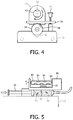
- FIG. 4 is a partially cross-sectional end view of the stirrer device of FIG. 3 when mounted in proximity to a syringe by a syringe pump.
- FIG. 5 is a side view of the stirrer device of FIG. 3 mounted in proximity to a syringe by a syringe pump.
- the lower housing 20 contains a variable speed motor with gear train and a processor which controls the speed at which the motor rotates a worm gear 26 that advances a plate 28 mounted on two guide rods.
- the plate 28 advances as indicated by the arrow, pressing the plunger 32 of a syringe 16 into the barrel of the syringe (indicated at 16 ) and thereby expelling the fluid in the syringe at a controlled rate of flow.
- the barrel of the syringe rests in a groove in a syringe mount 22 during operation and is retained in place by a spring-loaded bar 25 that is positioned onto the syringe barrel by a release knob 24 .
- the plate 28 advances to the right, pressing the plunger 32 into the syringe and expelling its fluid out the distal end of the syringe.
- FIG. 3 illustrates in perspective a magnetic stirrer 40 constructed in accordance with the principles of the present invention.
- the stirrer comprises a frame with an enclosure 44 at one end which houses a motor and its reduction gearbox.
- the motor is a 6 volt motor with a drive shaft speed variable up to 200 rpm.
- the motor rotates an aluminum rod 42 having a bearing-mounted shaft 60 .
- the rod is about 5 cm in length, which is sufficient to oppose the barrel of a 30 cc syringe.
- Affixed around the outer circumference of the rod 42 are a number of disc magnets 50 .
- a groove 48 is formed in the base 46 of the stirrer 40 and extends along the entire length of the frame.
- the stirrer 40 is shown in use in a partially cross-sectional end view in FIG. 4 when mounted on the barrel 34 of a syringe in a syringe pump.
- the barrel 34 of the syringe is seen to rest in a groove 36 in the syringe mount 22 of the syringe pump, and would normally be held in place by the spring-loaded bar 25 .
- the stirrer 40 is positioned on top of the syringe barrel with the barrel extending partially into the groove 48 in the base 46 of the stirrer.
- the spring-loaded bar 25 extends through the stirrer, retaining stirrer base 46 in position on top of the syringe and the syringe in its proper position in the syringe pump.
- the rotating rod 42 and its magnets 50 are thus maintained in a substantially parallel alignment with the barrel of the syringe.
- the stirrer When the stirrer is actuated, its motor rotates the rod 42 as indicated by the curved arrow, and the magnets 50 on the circumference of the rod 42 are continually rotated over the syringe, moving the magnetic beads inside the syringe barrel 34 through magnetic attraction and repulsion.
- groove 48 in this implementation is seen to be a squared groove, the groove can also be a concave curved groove which contacts more of the surface of the syringe barrel when engaged.
- a squared groove 48 as shown has been found to be sufficient to engage the syringe and be held in place by the bar 25 .
- FIG. 5 is a side view of the assembly of FIG. 4 .
- This illustration shows the magnetic beads 52 in the microbubble solution in the syringe barrel 34 .
- the magnets 50 are quarter-inch diameter (0.64 cm) Samarium cobalt disc magnets SC2512-500 available from Dura Magnetics, Inc. of Sylvania, Ohio, USA.
- the magnetic beads 52 are approximately 5 mm in length and 2 mm in diameter.
- Such beads are available from Cole-Parmer Instrument Company, LLC of Vernon Hills, Ill., USA as part number 08545-02.
- the magnets affixed to the stirrer rod 42 are powerful enough and pass close enough (approximately 5 mm) to the syringe barrel 34 and the magnetic beads 52 to move/spin the magnetic beads located inside the syringe.
- the stirrer rod 42 is rotated by the stirrer motor, it rotates the magnets 50 , which in turn move the magnetic beads 52 within the syringe, agitating the solution and thus preventing the microbubble solution from stratifying.
- this assembly easily stirs the microbubble solution without causing microbubble destruction.
- Other rotation speeds may be used, depending on factors such as the concentration of microbubbles, the number of beads used, and the size of the syringe. However, if the speed is too low, the microbubbles will still stratify; if the rotation speed is too high, the magnetic coupling between the magnets 50 on the stirrer rod 42 and the magnetic beads 52 separates, again resulting in insufficient stirring of the microbubble solution. Selective adjustment of the rotational speed is often required.
- microbubble solutions are usually packaged in a vial with a rubber membrane as are other injectable liquids.
- the microbubble solution may be aspirated from such a vial by use of a 20 gauge or larger needle attached to the distal end of the syringe which pierces the membrane to withdraw the microbubble solution.
- microbubble solution is required for continuous infusion during a one hour sonothrombolysis treatment. This equates to a flow rate of 0.83 ml/min.
- the amount of microbubble solution in the syringe should be 50 ml plus an additional amount to enable priming of the infusion tube set, plus a further amount to account for the inability to fully depress the plunger to the end of the syringe barrel due to the presence of the magnetic beads in the barrel of the syringe.
- this additional amount of microbubble solution is about 10 ml, bringing the total amount of solution required to about 60 ml in many cases.
- the length of the tubing is kept as short as possible between the distal end of the syringe and the catheterized infusion site.
- the tubing length is restricted to 30 cm or less. Tubing length of 10 cm or less has been found to result in no significant microbubble stratification in the infusion tubing. A significant rate of flow will also help prevent stratification.
- sterile magnetic beads In use, several sterile magnetic beads, at least two or more, are placed in the barrel of a syringe and the plunger inserted as far as it can go into the barrel.
- a 12 gauge or larger needle is attached to the distal end of the syringe and used to pierce the membrane of a vial of microbubble solution.
- the solution is drawn into syringe by retracting the plunger until the required amount of solution, generally 50 ml or more, fills the syringe.
- the syringe needle is pointed upward and the plunger depressed slightly to expel any air in the barrel.
- the needle is removed and infusion tubing leading to a transcutaneous catheter is attached to the distal end of the syringe.
- the syringe is placed in the groove of the syringe mount of a syringe pump and the magnetic stirrer placed on the barrel of the syringe.
- the spring-loaded retention bar of the syringe pump is inserted through the stirrer and springs downward to hold the stirrer and syringe in place on the pump and the stirrer is turned on. If necessary, its speed is adjusted so that stratification is prevented without significant microbubble destruction.
- the syringe pump is actuated to prime the tubing, if necessary, by injecting microbubble solution (or saline) into the tubing. After priming the catheter is inserted into a vein of the patient.
- the syringe pump is actuated to begin the injection of a continuous, controlled amount of microbubble solution into the patient while ultrasound is administered to the patient transcranially.
- An injection of t-PA can be added to the solution if desired via another infusion pump and connected tubing.
- the stirrer turned off, and the catheter withdrawn from the vein of the patient.
Landscapes
- Health & Medical Sciences (AREA)
- Life Sciences & Earth Sciences (AREA)
- Public Health (AREA)
- General Health & Medical Sciences (AREA)
- Veterinary Medicine (AREA)
- Animal Behavior & Ethology (AREA)
- Engineering & Computer Science (AREA)
- Biomedical Technology (AREA)
- Nuclear Medicine, Radiotherapy & Molecular Imaging (AREA)
- Heart & Thoracic Surgery (AREA)
- Surgery (AREA)
- Vascular Medicine (AREA)
- Chemical & Material Sciences (AREA)
- Chemical Kinetics & Catalysis (AREA)
- Molecular Biology (AREA)
- Radiology & Medical Imaging (AREA)
- Anesthesiology (AREA)
- Hematology (AREA)
- Medical Informatics (AREA)
- Orthopedic Medicine & Surgery (AREA)
- Infusion, Injection, And Reservoir Apparatuses (AREA)
Abstract
Description
Claims (19)
Priority Applications (1)
| Application Number | Priority Date | Filing Date | Title |
|---|---|---|---|
| US15/735,981 US10695078B2 (en) | 2015-06-30 | 2016-06-23 | Infusion system and method for sonothrombolysis stroke treatment |
Applications Claiming Priority (3)
| Application Number | Priority Date | Filing Date | Title |
|---|---|---|---|
| US201562186606P | 2015-06-30 | 2015-06-30 | |
| US15/735,981 US10695078B2 (en) | 2015-06-30 | 2016-06-23 | Infusion system and method for sonothrombolysis stroke treatment |
| PCT/IB2016/053731 WO2017001980A1 (en) | 2015-06-30 | 2016-06-23 | Infusion system and method for sonothrombolysis stroke treatment |
Publications (2)
| Publication Number | Publication Date |
|---|---|
| US20180185040A1 US20180185040A1 (en) | 2018-07-05 |
| US10695078B2 true US10695078B2 (en) | 2020-06-30 |
Family
ID=56289551
Family Applications (1)
| Application Number | Title | Priority Date | Filing Date |
|---|---|---|---|
| US15/735,981 Active 2036-10-04 US10695078B2 (en) | 2015-06-30 | 2016-06-23 | Infusion system and method for sonothrombolysis stroke treatment |
Country Status (3)
| Country | Link |
|---|---|
| US (1) | US10695078B2 (en) |
| EP (1) | EP3316927B1 (en) |
| WO (1) | WO2017001980A1 (en) |
Families Citing this family (2)
| Publication number | Priority date | Publication date | Assignee | Title |
|---|---|---|---|---|
| AU2019270182B2 (en) * | 2018-05-18 | 2024-11-21 | Bard Peripheral Vascular, Inc. | Microsphere containment systems and methods |
| GB2642542A (en) * | 2024-07-12 | 2026-01-14 | Protondx Ltd | A sample treatment apparatus |
Citations (10)
| Publication number | Priority date | Publication date | Assignee | Title |
|---|---|---|---|---|
| US4741732A (en) * | 1984-05-10 | 1988-05-03 | The University Of Melbourne | Open-loop control of drug infusion |
| US20020154570A1 (en) | 2001-04-24 | 2002-10-24 | Dade Behring Inc. | Method and apparatus for mixing liquid samples in a container using rotating magnetic fields |
| US20030126914A1 (en) | 2001-06-26 | 2003-07-10 | Hvidtfeldt Kristian Jacob | Blood analyzer, blood sample handler, and method for handling a blood sample |
| US6706020B1 (en) | 1998-08-28 | 2004-03-16 | Schering Aktiengesellschaft | Syringes and injectors incorporating magnetic fluid agitation devices |
| US6726650B2 (en) * | 1997-12-04 | 2004-04-27 | Bracco Research S.A. | Automatic liquid injection system and method |
| US6783003B2 (en) * | 2000-09-19 | 2004-08-31 | Kendell Simm | Hypodermic needle holder |
| US20040253183A1 (en) * | 2002-01-25 | 2004-12-16 | Uber Arthur E. | Apparatus, system and method for generating bubbles on demand |
| US20090012497A1 (en) | 2006-12-29 | 2009-01-08 | Medrad, Inc. | Systems and methods of delivering a dilated slurry to a patient |
| US20150131405A1 (en) * | 2013-11-08 | 2015-05-14 | Xerox Corporation | Magnetic mixing for continuous latex preparation |
| US10159948B2 (en) * | 2013-03-04 | 2018-12-25 | 3P Innovation Limited | Drum agitation actuator having a series of offset magnets |
Family Cites Families (1)
| Publication number | Priority date | Publication date | Assignee | Title |
|---|---|---|---|---|
| US9630028B2 (en) | 2006-08-11 | 2017-04-25 | Koninklijke Philips N.V. | Ultrasound system for cerebral blood flow imaging and microbubble-enhanced blood clot lysis |
-
2016
- 2016-06-23 EP EP16733213.9A patent/EP3316927B1/en active Active
- 2016-06-23 WO PCT/IB2016/053731 patent/WO2017001980A1/en not_active Ceased
- 2016-06-23 US US15/735,981 patent/US10695078B2/en active Active
Patent Citations (10)
| Publication number | Priority date | Publication date | Assignee | Title |
|---|---|---|---|---|
| US4741732A (en) * | 1984-05-10 | 1988-05-03 | The University Of Melbourne | Open-loop control of drug infusion |
| US6726650B2 (en) * | 1997-12-04 | 2004-04-27 | Bracco Research S.A. | Automatic liquid injection system and method |
| US6706020B1 (en) | 1998-08-28 | 2004-03-16 | Schering Aktiengesellschaft | Syringes and injectors incorporating magnetic fluid agitation devices |
| US6783003B2 (en) * | 2000-09-19 | 2004-08-31 | Kendell Simm | Hypodermic needle holder |
| US20020154570A1 (en) | 2001-04-24 | 2002-10-24 | Dade Behring Inc. | Method and apparatus for mixing liquid samples in a container using rotating magnetic fields |
| US20030126914A1 (en) | 2001-06-26 | 2003-07-10 | Hvidtfeldt Kristian Jacob | Blood analyzer, blood sample handler, and method for handling a blood sample |
| US20040253183A1 (en) * | 2002-01-25 | 2004-12-16 | Uber Arthur E. | Apparatus, system and method for generating bubbles on demand |
| US20090012497A1 (en) | 2006-12-29 | 2009-01-08 | Medrad, Inc. | Systems and methods of delivering a dilated slurry to a patient |
| US10159948B2 (en) * | 2013-03-04 | 2018-12-25 | 3P Innovation Limited | Drum agitation actuator having a series of offset magnets |
| US20150131405A1 (en) * | 2013-11-08 | 2015-05-14 | Xerox Corporation | Magnetic mixing for continuous latex preparation |
Also Published As
| Publication number | Publication date |
|---|---|
| WO2017001980A1 (en) | 2017-01-05 |
| EP3316927B1 (en) | 2020-03-25 |
| EP3316927A1 (en) | 2018-05-09 |
| US20180185040A1 (en) | 2018-07-05 |
Similar Documents
| Publication | Publication Date | Title |
|---|---|---|
| US8679051B2 (en) | Microbubble medical devices | |
| US8470298B2 (en) | Method of preparing a medium with bubbles formed therein for contemporaneous injection | |
| CA2433205A1 (en) | Drug delivery, bodily fluid drainage, and biopsy device with enhanced ultrasonic visibility | |
| US8308741B2 (en) | Systems and methods for automatically inserting a needle into a living subject | |
| US9814827B2 (en) | Systems and methods of delivering a dilated slurry to a patient | |
| AU736835B2 (en) | Automatic liquid injection system and method | |
| CN109152583A (en) | Systems and methods for dissolving thrombus and delivering pharmaceutical agents | |
| US20200360711A1 (en) | Delivery of magnetic particles in conjunction with therapeutic and/or diagnostic agents | |
| JP2018519060A5 (en) | ||
| JP2004510650A (en) | Suspending agent supply apparatus and its supply method | |
| US11129977B2 (en) | Systems and methods for therapeutic agent delivery | |
| CA2584638C (en) | Medical device for generating transient bubbles | |
| US10695078B2 (en) | Infusion system and method for sonothrombolysis stroke treatment | |
| US20240148950A1 (en) | Dialysis catheter clearance device and associated method | |
| JP2004041484A (en) | Chemical injection device | |
| WO2009001243A1 (en) | Apparatus for controlled delivery of molecules using a controlled injection system | |
| US20230007883A1 (en) | Injection pump needle mechanics | |
| WO2025193839A1 (en) | Systems and methods for enhanced operational parameters of an ultrasound catheter | |
| CN113577407A (en) | Remote control accurate liquid injection/suction control device for interventional therapy |
Legal Events
| Date | Code | Title | Description |
|---|---|---|---|
| AS | Assignment |
Owner name: KONINKLIJKE PHILIPS N.V., NETHERLANDS Free format text: ASSIGNMENT OF ASSIGNORS INTEREST;ASSIGNORS:SEIP, RALF;LEYVI, EVGENIY;RAJU, BALASUNDAR IYYAVU;SIGNING DATES FROM 20160729 TO 20160801;REEL/FRAME:044377/0520 |
|
| FEPP | Fee payment procedure |
Free format text: ENTITY STATUS SET TO UNDISCOUNTED (ORIGINAL EVENT CODE: BIG.); ENTITY STATUS OF PATENT OWNER: LARGE ENTITY |
|
| STPP | Information on status: patent application and granting procedure in general |
Free format text: DOCKETED NEW CASE - READY FOR EXAMINATION |
|
| STPP | Information on status: patent application and granting procedure in general |
Free format text: NON FINAL ACTION MAILED |
|
| STPP | Information on status: patent application and granting procedure in general |
Free format text: RESPONSE TO NON-FINAL OFFICE ACTION ENTERED AND FORWARDED TO EXAMINER |
|
| STPP | Information on status: patent application and granting procedure in general |
Free format text: FINAL REJECTION MAILED |
|
| STPP | Information on status: patent application and granting procedure in general |
Free format text: RESPONSE AFTER FINAL ACTION FORWARDED TO EXAMINER |
|
| STPP | Information on status: patent application and granting procedure in general |
Free format text: NOTICE OF ALLOWANCE MAILED -- APPLICATION RECEIVED IN OFFICE OF PUBLICATIONS |
|
| STCF | Information on status: patent grant |
Free format text: PATENTED CASE |
|
| MAFP | Maintenance fee payment |
Free format text: PAYMENT OF MAINTENANCE FEE, 4TH YEAR, LARGE ENTITY (ORIGINAL EVENT CODE: M1551); ENTITY STATUS OF PATENT OWNER: LARGE ENTITY Year of fee payment: 4 |