US10694550B2 - Apparatus and method for initial access in wireless communication system - Google Patents
Apparatus and method for initial access in wireless communication system Download PDFInfo
- Publication number
- US10694550B2 US10694550B2 US15/400,602 US201715400602A US10694550B2 US 10694550 B2 US10694550 B2 US 10694550B2 US 201715400602 A US201715400602 A US 201715400602A US 10694550 B2 US10694550 B2 US 10694550B2
- Authority
- US
- United States
- Prior art keywords
- base station
- terminal
- random access
- signal strength
- access signals
- Prior art date
- Legal status (The legal status is an assumption and is not a legal conclusion. Google has not performed a legal analysis and makes no representation as to the accuracy of the status listed.)
- Active, expires
Links
Images


Classifications
-
- H—ELECTRICITY
- H04—ELECTRIC COMMUNICATION TECHNIQUE
- H04W—WIRELESS COMMUNICATION NETWORKS
- H04W76/00—Connection management
- H04W76/10—Connection setup
-
- H—ELECTRICITY
- H04—ELECTRIC COMMUNICATION TECHNIQUE
- H04W—WIRELESS COMMUNICATION NETWORKS
- H04W48/00—Access restriction; Network selection; Access point selection
- H04W48/20—Selecting an access point
-
- H—ELECTRICITY
- H04—ELECTRIC COMMUNICATION TECHNIQUE
- H04W—WIRELESS COMMUNICATION NETWORKS
- H04W56/00—Synchronisation arrangements
- H04W56/001—Synchronization between nodes
-
- H—ELECTRICITY
- H04—ELECTRIC COMMUNICATION TECHNIQUE
- H04W—WIRELESS COMMUNICATION NETWORKS
- H04W64/00—Locating users or terminals or network equipment for network management purposes, e.g. mobility management
-
- H04W72/085—
-
- H—ELECTRICITY
- H04—ELECTRIC COMMUNICATION TECHNIQUE
- H04W—WIRELESS COMMUNICATION NETWORKS
- H04W72/00—Local resource management
- H04W72/50—Allocation or scheduling criteria for wireless resources
- H04W72/54—Allocation or scheduling criteria for wireless resources based on quality criteria
- H04W72/542—Allocation or scheduling criteria for wireless resources based on quality criteria using measured or perceived quality
-
- H—ELECTRICITY
- H04—ELECTRIC COMMUNICATION TECHNIQUE
- H04W—WIRELESS COMMUNICATION NETWORKS
- H04W74/00—Wireless channel access
- H04W74/08—Non-scheduled access, e.g. ALOHA
- H04W74/0833—Random access procedures, e.g. with 4-step access
-
- H—ELECTRICITY
- H04—ELECTRIC COMMUNICATION TECHNIQUE
- H04W—WIRELESS COMMUNICATION NETWORKS
- H04W16/00—Network planning, e.g. coverage or traffic planning tools; Network deployment, e.g. resource partitioning or cells structures
- H04W16/24—Cell structures
- H04W16/28—Cell structures using beam steering
-
- H—ELECTRICITY
- H04—ELECTRIC COMMUNICATION TECHNIQUE
- H04W—WIRELESS COMMUNICATION NETWORKS
- H04W88/00—Devices specially adapted for wireless communication networks, e.g. terminals, base stations or access point devices
- H04W88/02—Terminal devices
-
- H—ELECTRICITY
- H04—ELECTRIC COMMUNICATION TECHNIQUE
- H04W—WIRELESS COMMUNICATION NETWORKS
- H04W88/00—Devices specially adapted for wireless communication networks, e.g. terminals, base stations or access point devices
- H04W88/08—Access point devices
Definitions
- the present disclosure relates to an initial access method in wireless communication system, more particularly, to an initial access method between a terminal and at least one base station.
- the 5G or pre-5G communication system is also called a ‘Beyond 4G Network’ or a ‘Post LTE System’.
- the 5G communication system is considered to be implemented in higher frequency (mmWave) bands, e.g., 60 GHz bands, so as to accomplish higher data rates.
- mmWave e.g., 60 GHz bands
- MIMO massive multiple-input multiple-output
- FD-MIMO Full Dimensional MIMO
- array antenna an analog beam forming, large scale antenna techniques are discussed in 5G communication systems.
- RANs Cloud Radio Access Networks
- D2D device-to-device
- wireless backhaul moving network
- cooperative communication Coordinated Multi-Points (CoMP), reception-end interference cancellation and the like.
- CoMP Coordinated Multi-Points
- FQAM Hybrid FSK and QAM Modulation
- SWSC sliding window superposition coding
- ACM advanced coding modulation
- FBMC filter bank multi carrier
- NOMA non-orthogonal multiple access
- SOMA sparse code multiple access
- a random-access channel is a shared channel used by UEs to access the mobile network, without requiring prior knowledge of the network.
- RACH random-access channel
- the UE must synchronize to each frequency in turn to establish it corresponds to an appropriate operator. This is achieved through an initial synchronisation process. Once synchronized to a particular frequency, the UE can determine whether it corresponds to an appropriate operator through the master information and System information blocks transmitted periodically by each network. The next step is known as the Random Access Procedure which allows the network to identify that a UE is trying to connect.
- the first message of the random access procedure comprises the UE sending a specific RACH preamble over the shared RACH.
- the identity of the UE is also transmitted. If the RACH preamble is received by the LTE base station (the evolved Node B, eNB) it sends a random access response including an uplink grant resource for further communication between the UE and the eNB, specifically for the transmission of a Radio Resource Control (RRC) Connection Request message by the UE in which the UE seeks permission to connect to the network.
- RRC Radio Resource Control
- the antenna pattern of the base station is sectorized and the antenna pattern of the UE is most likely omnidirectional. Therefore, the reception of the random access preamble sent by the UE (within an RA Channel, RACH) is principally affected by the distance between the eNB and the UE.
- RACH Random access preamble sent by the UE
- beam-foil ling transmission is employed at both the mmSC and the UE to tackle the increased path loss.
- the high directivity in mm-wave technologies makes the conventional design of initial access procedures (such as for LTE based on broadcast signals) unsuitable. Therefore, for a mm-wave initial access procedure there is a need to pair the beams of a mmSC and a UE, which may take a considerable amount of time.
- Certain embodiments of the disclosure significantly reduce the beam discovery time of the initial access procedure, enhance the robustness against signal blockage in both line of sight (LOS) and non-line of sight (NLOS) situations, and reduce the cost and complexity of the UE. Certain embodiments of the disclosure facilitate the establishment of asymmetric uplink and downlink, and multiple connections.
- LOS line of sight
- NLOS non-line of sight
- the present disclosure allows for efficient and fast initial access for a UE to a standalone mm-wave network without requiring the presence of an overlaid legacy network operating on a lower frequency.
- an initial access method in a wireless communications network comprising a cluster of at least three base stations arranged to communicate with a mobile terminal using directional beams, the method comprising transmitting a random access signal from the mobile terminal through a first sweep comprising a plurality of mobile terminal transmission beams; measuring at three or more base stations, each operating a single base station reception beam during the measurements, a power level of the received random access signal from the mobile terminal for the plurality of mobile terminal transmission beams in the first sweep, selecting, for at least one base station, a base station reception beam on the basis of the measurement results, transmitting a random access signal from the mobile terminal through a second sweep comprising the plurality of mobile terminal transmission beams while the at least one base station operates a selected base station reception beam; and establishing an uplink connection between the mobile terminal and one of the base stations if that base station receives the random access signal from the mobile terminal with a power level above a first threshold.
- the method may further comprise estimating the location of the mobile terminal based upon the measurement results, wherein the base station reception beam is selected on the basis of the estimated location of the mobile terminal.
- the method may further comprise selecting a subset of base station reception beams on the basis of the measurement results, and transmitting a random access signal from the mobile terminal through further sweeps comprising the plurality of mobile terminal transmission beams while the at least one base station operates in turn each one of the selected subset of base station reception beams.
- the method may further comprise synchronising the transmission of the random access signal from the mobile terminal according to a synchronisation signal transmitted by one or more base stations.
- the method may further comprise measuring the power level of the received random access signal from the mobile terminal at a plurality of base stations, and selecting, for at least one base station, a base station reception beam on the basis of a subset of the measurement results for three or more of base stations.
- the method may further comprise transmitting the measurement results from each base station to the other base stations or to a separate network component, wherein a base station reception beam is selected for at least one base station, at each base station on the basis of received and measured measurement results, at a single base station on the basis of received and measured measurement results, the selected base station reception beam being transmitted to at least one other base station; or at the separate network component, the selected base station reception beam being transmitted to at least one base station.
- the cluster of base stations may be directly connected via backhaul links for communicating measurement results.
- the method may further comprise measuring at three or more base stations, each operating a selected base station reception beam, a power level of the received random access signal from the mobile terminal for the plurality of mobile terminal transmission beams in the second sweep, selecting, for at least one base station, a further base station reception beam on the basis of the measurement results, transmitting a random access signal from the mobile terminal through a third sweep comprising the plurality of mobile terminal transmission beams while the at least one base station operates a further selected base station reception beam, and establishing an uplink connection between the mobile terminal and one of the base stations if that base station receives the random signal from the mobile terminal with a power level above the first threshold.
- a method of operating a base station in a wireless communications network comprising a cluster of at least three base stations arranged to communicate with a mobile terminal using directional beams, the method comprising: receiving a random access signal from the mobile terminal through a single sweep comprising a plurality of mobile terminal transmission beams while operating a first base station reception beam; measuring a power level of the received random access signal from the mobile terminal for the plurality of mobile terminal transmission beam in the first sweep; obtaining a selection of a base station reception beam on the basis of the measurement results; receiving a random access signal from the mobile terminal through a second sweep comprising the plurality of mobile terminal transmission beams while operating the selected base station reception beam; and establishing an uplink connection between the mobile terminal and the base station if the random signal is received from the mobile terminal with a signal strength above a first threshold.
- Obtaining a selection of a base station reception beam may comprise: transmitting the measurement results to at least two further base stations in the cluster, or to a separate network component, and receiving an estimate of the location of the mobile terminal or a selection of a base station reception beam; or transmitting the measurement results to at least two further base stations in the cluster, receiving corresponding measurement results from at least two further base stations in the cluster and selecting a base station reception beam based upon the received and measured measurement results.
- a base station arranged to perform the above method.
- Another aspect of the present disclosure provides a computer program comprising instructions arranged, when executed, to implement a method and/or apparatus in accordance with any one of the above-described aspects.
- a further aspect provides machine-readable storage storing such a program.
- FIG. 1A illustrates a UE performing an initial access procedure with a single mmSC
- FIG. 1B illustrates a UE performing an initial access procedure with a cluster of mmSCs
- FIG. 2 illustrates a system model in accordance with an embodiment of the present disclosure
- FIG. 3 illustrates PDP measurement results for a single mmSC according to the system model of FIG. 2 in response to a UE transmission full sweep;
- FIG. 4 illustrates PDP measurement results for a cluster of three mmSCs according to the system model of FIG. 2 in response to a UE transmission full sweep in accordance with an embodiment of the present disclosure
- FIG. 5 illustrates mmSC reception beam reordering according to an estimated UE location determined through the system model of FIG. 2 ;
- FIGS. 6A and 6B illustrate the determination of estimation areas for the location of a UE
- FIG. 7 illustrates the effect of non-line of sight transmission paths
- FIG. 8 is a graph illustrating the effect of cluster size on the probability of line of sight paths being selected.
- FIGS. 9A and 9B illustrate two options for asymmetric uplink and downlink connections, FIG. 9B further illustrating multiple connections;
- FIGS. 10A and 10B illustrate a simulation of UE location estimation according to certain embodiments of the present disclosure
- FIGS. 11A and 11B illustrate simulations of initial access time reduction according to certain embodiments of the present disclosure
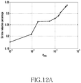
- FIGS. 12A and 12B illustrate simulations of percentage initial access time reduction according to certain embodiments of the present disclosure
- FIG. 13 illustrates a simulation of initial access time when the size of a cluster changes according to certain embodiments of the present disclosure
- FIG. 14 illustrates the structure of a 5G base station in accordance with an embodiment of the present disclosure
- FIG. 15 illustrates the structure of a UE in accordance with an embodiment of the present disclosure
- FIG. 16 illustrates a flow chart of a base station in accordance with an embodiment of the present disclosure.
- FIG. 17 illustrates a flow chart of a UE in accordance with an embodiment of the present disclosure.
- FIGS. 1A through 17 discussed below, and the various embodiments used to describe the principles of the present disclosure in this patent document are by way of illustration only and should not be construed in any way to limit the scope of the disclosure. Those skilled in the art will understand that the principles of the present disclosure may be implemented in any suitably arranged electronic device.
- This disclosure relates to an Initial Access (IA) method in a wireless communications network comprising a cluster of at least three base stations arranged to communicate with a mobile terminal using directional beams.
- IA Initial Access
- certain embodiments of the disclosure to a coordinated initial access method conducted through a Random Access (RA) procedure in such a wireless communications network.
- RA Random Access
- certain embodiments of the present disclosure relate to an initial access method that allows for coordinated initial access for a mobile terminal in a standalone millimetre wave (mm-wave) wireless communication network.
- the standalone millimetre wave wireless communication network may comprise a cluster of millimetre wave small cells (mmSC) such as have been proposed for Fifth Generation (5G) mobile communication networks.
- mmSC millimetre wave small cells
- a millimetre wave wireless communication network comprises a network in which communication between a mobile terminal and a network access point take place through directional beams in the Extremely High Frequency (EHF) band (roughly in the 30-300 GHz range), such as an unlicensed 60 GHz band.
- EHF Extremely High Frequency
- the UE is assumed to have dual RF interfaces for the LTE link and the mm-wave link respectively. It is clear that there is a cost overhead associated with this requirement for dual RF interfaces.
- the LTE network may be accessed in a conventional fashion in which the UE connects to an LTE macro cell, and the LTE network may be used to disseminate beam sequence information to the UE and the mmSCs to establish effective beam pairs.
- the initial access procedure is facilitated by splitting out the user plane and the control plane and locating the control plane in the overlaid legacy LTE network where the control signalling and context information of a UE can be conveyed.
- the user plane is located in the mmSC network.
- the UE establishes connections with one or multiple mmSCs.
- the UE measures the downlink channel from one or more mmSC using reference signals transmitted by the mmSC and generates a measurement report.
- the UE sends the measurement report to the LTE macro cell via the established LTE link.
- the LTE macro cell sends a recommended reception beam set to the mmSC via backhaul links.
- the mmSCs then reorder the reception beams to put the recommended beams in the forepart when sweeping (that is, to ensure that the recommended beams are swept first).
- the initial access time is reduced at the cost of significantly increased signalling overhead and increasing the hardware complexity of the network and the UE.
- base station may be used to refer to any network component, such as a mmSC capable of communicating with a UE using a directional beam pair.
- this shows a single UE 100 and a single mmSC 102 in a standalone mm-wave network.
- the initial access procedure comprises the UE transmits a random access (RA) preamble through beams 104 and the mmSC receives the RA preamble through beams 106 .
- RA random access
- the UE 100 will be considered to transmit through only a single beam 104 at a time and the mmSC 102 will be considered to only receive signals through a single beam 106 at a time.
- only a single UE transmission beam is shown shaded, comprising the currently operated transmission beam, which can be examined by the mmSC, and the remaining transmission beams are shown dashed.
- the UE 100 needs to conduct a full transmission beam sweep for a given mmSC reception beam 106 , and each possible reception beam 106 is used to examine the UE transmission beam sweep. It is assumed that the UE transmission beam sweep is synchronised to the mmSC reception beams through the UE monitoring the downlink synchronisation channel (SCH) prior to beginning uplink random access. There is no requirement that a downlink channel has been established, only that the SCH is monitored for synchronisation. During each UE transmission beam sweep, it is assumed that the mmSC reception beam 106 does not change.
- SCH downlink synchronisation channel
- This exhaustive beam sweep method not only causes a very long initial access time (N tx N rx T RA as noted above), it also introduces significant beam scan overhead. Moreover, the repeated transmission of RA preambles increases the energy consumption for the UE and thus might easily drain the battery of the UE, which will typically be a portable device.
- the example of FIG. 1A assumes predefined codebooks at the mmSC and the UE in which the number, shape and orientation of transmission and reception beams is predefined. The skilled person will readily understand how the example of FIG. 1A and the exhaustive search procedure described above can be extended to cover the case that the mmSC and the UE can adaptively steer their beam direction and width.
- FIG. 1B illustrates an extension to FIG. 1A considering the case in which there is a dense deployment of mmSCs 102 and the UE 100 can communicate with any one of the mmSCs 102 .
- the mmSCs 102 can be clustered based on certain pre-determined sets, for instance according to proximity, and the mmSCs 102 within each cluster are connected via backhaul links.
- FIG. 1B shows an illustration of a mm-wave initial access procedure between a single UE 100 and a coordinating cluster of three mmSCs 102 (S 1 , S 2 , S 3 ) connected via backhaul links 108 .
- each mmSC can also participate in neighboring clusters, being formed at the apexes of a grid of clusters. Again, it is assumed that during each full scan of UE transmission beams the mmSC reception beams do not change through synchronization using the downlink synchronization channel.
- the backhaul links 108 can be any suitable communication link, including conventional wired or wireless links. If the mmSCs 102 share their location and beam scan information via the backhaul links 108 with extremely small latency, there is a possibility that their reception beam sweep procedures can be coordinated jointly to accelerate the initial access procedure.
- Each mmSC 102 knows the location and selected reception beams of the other two mmSCs 102 , for a given UE transmission beam, and so in order to effectively scan the space between the cluster of three mmSCs only a single mmSC 102 (S 1 ) needs to sweep one third of the total reception beam searching space.
- S 1 a single mmSC 102
- FIG. 1B illustrates that each mmSC 102 is shown illustrated with only a third of the possible reception beams compared with the illustration of FIG. 1A , S 2 and S 3 serving to scan the space within adjacent clusters.
- the initial access time can be reduced to 1 ⁇ 3 of its original value when the UE 100 is located in the centre of the cluster.
- the present disclosure effectively builds on the clustered mmSCs scenario depicted in FIG. 1B and provides for a higher level of coordination between the mmSCs.
- the mmSCs exchange measurement reports with each other via the backhaul links. Based on the measurement reports, the location of the UE can be estimated allowing for one or more of the cluster of mmSCs to select an appropriate reception beam directed towards the estimated UE location before the next UE transmission beam sweep.
- the initial access time can be effectively reduced.
- This estimation of the UE location based only on the RA preamble received by a cluster of mmSCs represents a clear departure from conventional approaches to initial access in a standalone mmSC network in which knowledge of the UE location can only be gained once the connection is complete.
- this illustrates a system model in accordance with an embodiment of the present disclosure.
- the system model assumes that there are three mmSCs 102 (S 1 , S 2 , S 3 ) in a cluster forming an equilateral triangle with side length D for simplicity.
- the extension to other triangles and clusters having more than three mmSCs will be readily appreciated by the skilled person, and the case of more than three mmSCs is described below.
- the UE 100 is assumed to be located in the triangle. Again, the extension to the case where the UE is located out of the triangle is straightforward.
- FIG. 2 illustrates the situation during a first UE sweep in which the UE transmits the RA preamble through each UE beam in turn and each mmSC is operating a randomly assigned reception beam.
- FIG. 2 illustrates the likely scenario in which none of the randomly assigned mmSC reception beams are directed towards the UE.
- the distances between the UE and the mm-wave SCs are assumed to be d 1 , d 2 and d 3 and angles in between are assumed to be ⁇ 1 , ⁇ 2 , and ⁇ 3 .
- the beam directions of the mmSC 102 and the UE 100 need to be aligned to tackle the propagation losses experienced with mm-wave communication. Only if the Power Density Profile (PDP) value (also referred to herein as the received signal strength or received power level) of the preamble received from the UE exceeds ⁇ ra is the RA preamble considered correctly received by the mmSC 102 such that a RA response message can be transmitted to the UE 100 .
- PDP Power Density Profile
- a measurement report can be generated, where for each UE beam index a PDP value is calculated.
- ⁇ UE,i is the angle between the main UE antenna lobe and the i th mmSC (identified in FIG. 2 in respect of an exemplary UE beam and S 3 )
- ⁇ sc,i is the angle between the main antenna lobe of the i th mmSC and the UE (identified in FIG. 2 in respect of an exemplary UE beam and S 3 )
- L is the path loss component and d, is the distance between the i th mmSC and the UE.
- a simplified directional antenna model is assumed for both the mmSC and the UE, as follows:
- G ⁇ ( ⁇ ) ⁇ G 0 - 3.01 ⁇ ( 2 ⁇ ⁇ ⁇ - 3 ⁇ d ⁇ ⁇ B ) 2 , 0 ⁇ ⁇ ⁇ ⁇ m ⁇ ⁇ l / 2 G sl , ⁇ m ⁇ ⁇ l / 2 ⁇ ⁇ ⁇ ⁇ ( 2 )
- ⁇ m ⁇ ⁇ l 2.6 ⁇ ⁇ - 3 ⁇ d ⁇ ⁇ B
- ⁇ G 0 10 ⁇ log ⁇ ( 1.6162 sin ⁇ ( ⁇ - 3 ⁇ d ⁇ ⁇ B / 2 ) ) 2
- ⁇ G sl - 0.4111 ⁇ ln ⁇ ( ⁇ - 3 ⁇ d ⁇ ⁇ B ) - 10.579 . ( 3 )
- ⁇ is an arbitrary angle within the range [0, ⁇ ]
- ⁇ ⁇ 3dB is the angle of half-power beam width
- ⁇ ml is the mail lobe width in units of degrees
- G 0 and G sl are the maximum antenna gain and the side lobe gain, respectively.
- the initial access is initiated by UE broadcasting a preamble sequence built by cyclically-shifting a Zadoff-Chu (ZC) sequence of prime length N zc , as follows:
- x u ⁇ ( n ) exp ⁇ [ - j ⁇ ⁇ ⁇ ⁇ ⁇ un ⁇ ( n + 1 ) N ZC ] , 0 ⁇ n ⁇ N ZC - 1 ( 5 )
- u is the index of the sequence.
- the preamble sequence will be transmitted using SC-FDMA and the detailed initial access and detection procedures can be found in 3GPP Technical Specification TS 36.300 V13.1.0 Overall Description, September 2015.
- the same ZC sequences and initial access procedure can be employed and the PDP of the received sequence is as follows:
- y(n) is the received preamble sequence and z u (1) is the discrete periodic correlation function at lag l.
- a measurement report can be generated, where for each UE beam index a PDP peak is obtained. More generally, each mmSC (base station) can measure the received signal from the UE in respect of a plurality of UE beam indices, which may not always correspond to a full scan. Such a measurement report for a single mmSC is illustrated in FIG. 3 . As can be seen, the PDP peak of UE beam index 5 is significantly larger than the others, which is presumed to be because the direction of this UE transmission beam points most closely towards the mmSC producing the measurement report.
- this measurement report can be shared with each member of the mmSC cluster.
- the UE's location can be coarsely estimated based on the measurement reports as will be described below.
- the mmSCs are therefore able to reorder the mmSC reception beams and move the best beams in the forepart when sweeping such that they are used first to examine the UE initial access transmissions.
- the mmSCs are divided into clusters, for instance with three mmSCs.
- each mmSC When a UE conducts a full sweep, each mmSC generates one measurement report.
- the measurement reports are exchanged via the backhaul links and the position of the UE is then estimated by the mmSCs.
- the mmSC reception beams are reordered. It will be appreciated that in other embodiments the mmSC reception beams can be reordered on the basis of the measurements without explicitly outputting the estimated UE location.
- an uplink connection can be established within one of the cluster of mmSCs.
- This uplink connection could either associate the UE to the same mmSC in downlink or a different mmSCs (asymmetric uplink and downlink).
- multiple uplink connections can subsequently be established using the existing uplink connection.
- a subset of all mmSC beams can be used, for instance the best beam assumed to point at the UE and its adjacent beams. Only this subset can be examined.
- the motivation of this embodiment is to reduce the number of mmSC reception beams to be examined.
- the rational of this embodiment is based on the fact that the estimation of the UE's location is an approximation. There is a probability that the best mmSC reception beam chosen does not actually point towards the UE (for instance, due to non-line of sight links as described below and also due to the limited choice of mmSC reception beams available, assuming the use of a codebook).
- each mmSC generates a measurement report. All reports are exchanged via the backhaul links and a subset of three or more reports can be chosen based on certain criterion to estimate the position of the UE. The criterion could be based on the measurement reports including the highest PDP peak those correspond to mmSCs most likely to be accessed successfully.
- account can be taken of existing load on each mmSC such that even if a mmSC identified the highest PDP peak it is not chosen if many UEs are already associated with that mmSC.
- the mmSC reception beams can be reordered or a subset of reception beams selected as noted above for a mmSC reception beam sweep.
- the mmSCs may not use a beam-forming codebook. Based on the UE location estimate, the mmSCs can tune their beam direction towards the UE and adjust the width of the reception beams in order to further accelerate the initial access procedure.
- Embodiments of the present disclosure can be divided into four phases: PDP measurement (as described above), coordinated beam sweep reordering (as a result of the UE location estimate), initial access, and asymmetric multi-cell association.
- PDP measurement as described above
- coordinated beam sweep reordering as a result of the UE location estimate
- initial access asymmetric multi-cell association.
- the involved mmSCs measure the PDP of the received preamble and share the measurement reports via the backhaul links.
- the second, beam sweep reordering phase mmSCs jointly estimate the best reception beam for each mmSC based on the measurement reports and reorder the mmSC reception beams to test the best reception beams first (alternatively, the estimation can be performed at a single point upon receipt of the measurement reports, and the appropriate mmSC reception beam disseminated to each mmSC).
- the UE conducts one or more full transmission beam sweeps during which the set of selected mmSC beams is used until an uplink connection is established successfully.
- the existing uplink connection can be used to establish multiple uplink connections which may or may not associate the UE to the same mmSC in the downlink.
- the mmSCs are connected via the backhaul links, they can be synchronized to start a reception beam sweep at the same time.
- the reception beam directions are randomly chosen at the beginning
- the UE conducts full beam sweep and transmits the preamble for each transmission beam index every T ra seconds.
- Each mmSC also calculates PDP values every T ra seconds and after N tx T ra seconds one UE full sweep is completed and a measurement report is generated. Within each measurement report, there are N tx PDP values, each corresponding to one UE transmission beam.
- FIG. 4 this illustrates a set of three measurement reports exchanged via the backhaul links as shown in FIG. 2 for the illustrated cluster of three mmSCs (S 1 , S 2 , S 3 ).
- Three peak values of the measurement reports identify three peak UE transmission beam index n 1 , n 2 and n 3 whose directions point at corresponding mmSCs (also labelled in FIG. 2 ).
- this location estimation can be performed independently at each mmSC. Alternatively, it can be performed centrally at a single mmSC or another network component, and the estimate disseminated. In some embodiments the measurement results may not be sent to each and every other mmSC in the cluster. It can be readily seen from the system model of FIG. 2 and the PDP measurement reports of FIG. 4 that ⁇ i (the angle from the UE to a pair of mmSCs in the cluster) can be estimated based on the peak UE transmission beam index as follows:
- ⁇ ⁇ i ⁇ 2 ⁇ ⁇ ⁇ ( n i + 1 - n i ) N tx , if ⁇ ⁇ n i + 1 > n i 2 ⁇ ⁇ ⁇ ( N tx - n i + n i + 1 ) N tx , if ⁇ ⁇ n i + 1 ⁇ n i ( 7 )
- Equation (7) is based on the assumption that there is a pre-defined codebook for UE transmission beams which is known in advance by the mmSCs. If the UE is adaptively steering the beam, this action must have been agreed with the mmSCs beforehand. For example, this can be done by following ways: the adaptive steering is pre-defined and agreed; or the adaptive steering is supervised by the mmSC via downlink broadcasting channel (PBCH). It will be appreciated that adaptive steering causes a larger signaling overhead. Fully adaptive beam sweep for the UE can be difficult and time consuming in practice.
- PBCH downlink broadcasting channel
- equation (7) yields only an estimate of the angle from the UE to a pair of mmSCs in the cluster because the direction of the UE transmission beam is not always perfectly aligned with the direction of the mmSCs as shown in FIG. 2 .
- the estimates angle ( ⁇ tilde over ( ⁇ ) ⁇ i ) corresponds to the angle between the pair of UE transmission beams that are most closely aligned to the pair of mmSCs, and as such resulted in the pair PDP peaks.
- the example of ⁇ tilde over ( ⁇ ) ⁇ 2 is labelled in FIG. 2 .
- the distances between the UE and each mmSC in the cluster can be determined by solving the following equations:
- the estimated location of the UE can be determined.
- the mmSCs can therefore reorder the reception beam set and choose the reception beams pointing at the estimated UE location in the next round of the UE transmission beam sweep as shown in FIG. 5 .
- the reception beam 106 for each mmSC 102 is generally pointing towards the estimated UE location 500 (within the constraints of a limited selection of reception beams within a mmSC codebook, if appropriate).
- FIG. 5 also illustrates that there is an offset between the true location of the UE 100 and the estimated UE location 500 .
- the cluster size can be larger than 3.
- the three measurements with the largest PDP peaks can be selected (or some other criterion applied), and the rest of the estimation procedure keeps the same.
- more than three of the measurement reports can be used to further enhance the UE location estimation accuracy.
- the UE location falls within the estimation area 600 .
- the UE location can be determined to be in the overlapping area of the estimation areas identified by the corresponding equations in (10). With each additional mmSC, an additional set of equations (10) is added and thus a further estimation area generated.
- the overlapping of all estimation areas 600 thus provides a smaller region 602 in which it is expected that the UE is located.
- FIG. 7 illustrates a situation in which for a cluster of three mmSCs, LOS links 700 are maintained to S 1 and S 2 but a LOS link 702 to mmSC S 3 through UE transmission beam 1041 is blocked by a blockage 704 such as a wall or a person.
- a blockage 704 such as a wall or a person.
- a reflector 706 which can reflect the UE preamble towards mmSC S 3 resulting in a Non-Line Of Sight (NLOS) link 708 being created. If this NLOS link is undetected then it will be appreciated that the estimated UE location might be entirely different from the actual UE location. The result is likely to be that none of the three mmSCs 102 can appropriately adjust their reception beams toward the UE 100 . This can either cause the initial access procedure to be delayed or for it to fail.
- NLOS Non-Line Of Sight
- NLOS links can be efficiently avoided if a cluster of mmSCs consists of more than three mmSCs. This is because the PDP measurement for a NLOS link is likely to be significantly lower than that for a LOS link. A larger cluster has redundancy in the sense PDP measurements from one or more mmSC can be avoided. If a subset of the strongest PDP measurements is selected then it is likely that the selected PDP measurement peaks will correspond to LOS links. For an assumed reflection coefficient of 0.7, such that the NLOS link is at least 1.5 dB worse than the LOS link, an Monte-Carlo simulation can be conducted with the following system settings:
- the blocking probability of each mmSC is P blk (the probability that there is no LOS link to the mmSC from the UE);
- the three mmSCs with the largest PDP peak are chosen to estimate the UE location.
- the probability P LOS that the three chosen mmSCs are not blocked is depicted in FIG. 8 as a function of the cluster size (N).
- the simulated results for P LOS are shown for two different values of P blk .
- P blk 0.1
- PLOS can be above 0.7 with the cluster size larger than 20.
- cluster size could be even larger than 20 and thus there is a high probability that LOS links will exist and be selected for estimating the UE location.
- NLOS links can be identified and eliminated through knowledge of the positions of the mmSCs, further increasing P LOS .
- FIG. 9A shows a UE 100 being connected to separate mmSCs 102 for downlink and uplink.
- the UE is associated with mmSC S 1 and in the uplink the UE is associated with mmSC S 2 .
- Uplink and downlink decoupling can be beneficial, for instance in the case of asymmetric downlink/uplink traffic.
- the mmSCs within one cluster are connected via backhaul links, multiple connections can be established to the same UE using the existing connection as shown in FIG. 9B .
- the UE can be further associated with multiple mm-wave SCs. Multiple connections advantageously reduce the possibility of degraded performance or loss of connection due to blockage.
- FIG. 10A shows the estimated UE location 500 using the proposed disclosure and the true location of the UE 100 .
- the mmSCs beam directions 106 are chosen randomly. As described above, after one UE transmission sweep round, an estimate for the UE location 500 is generated and the estimated location 500 is quite close to the actual location 100 . In the next UE transmission beam sweep round, as shown in FIG.
- the reception beams for the mmSCs 102 are directed generally towards the estimated UE location. Owing to the closeness of the UE location estimate 500 to its true location 100 , the reception beam for S 1 in fact also points at the UE 100 . In FIGS. 10A and 10B each axis expresses distance in meters.
- FIGS. 11A and 11B shows the percentage initial access time reduction achieved using the present disclosure expressed as a fraction of the initial access time conducted using a conventional exhaustive search).
- T ra_new and T ra_con are the initial access time according to an embodiment of the present disclosure and according to the conventional approach respectively.
- the reduction of initial access time decreases with increased UE transmission power, which is reasonable since with very high UE transmission power the PDP of a received UE preamble can be so strong that it exceeds the threshold even without transmission and reception beam paring.
- the initial access time is significantly reduced as a result of the present disclosure, especially towards the lower end of the transmission power of the UE.
- P miss the miss detection probability
- initial access time can be further reduced.
- P miss target which is normally used in LTE/LTE-A
- FIG. 13 shows the normalized initial access time when the size of the cluster (N sc ) changes.
- N sc the size of the cluster
- conventional exhausting searching is employed.
- FIG. 14 provides a schematic diagram of the structure of a mmSC 700 which is arranged to operate in accordance with the examples of the present disclosure described above.
- the mmSC includes a transmitter 702 arranged to transmit signals to a UE; a receiver 704 arranged to receive signals from the UEs; and a controller 706 arranged to control the transmitter and receiver and to perform processing such as in accordance with the above described initial access method.
- FIG. 15 provides a schematic diagram of the structure of a UE 800 which is arranged to operate in accordance with the examples of the present disclosure described above.
- the UE includes a transmitter 802 arranged to transmit signals to the mmSC; a receiver 804 arranged to receive signals from the mmSC; and a controller 806 arranged to control the transmitter and receiver and to perform processing.
- FIGS. 14 and 15 the transmitter, receiver, and controller have been illustrated as separate elements, any single element or plurality of elements which provide equivalent functionality can be used to implement the examples of the present disclosure described above.
- FIG. 16 illustrates a flow chart of a base station in accordance with an embodiment of the present disclosure.
- the base station receives a first random access signal.
- the base station receives, from a the first random access signal transmitted by a plurality of beams of the terminal according to a first sweep.
- the plurality of beams of the terminal can comprise transmission beams each corresponding to each of the UE transmission beam indices as illustrated in FIG. 3 .
- the base station determines a receive beam based on a signal strength of the first random access signal.
- the base station can measure the signal strength of the first random access signal.
- the base station can measure PDP value by a preamble of the first random access signal.
- the base station can transmit, to at least one other base station, information regarding the signal strength of the first random access signal and receive, from the at least one other base station, an estimate of a location of the terminal or a selection of the receive beam, to determine the receive beam.
- the base station can transmit, to a separate network component, information regarding the signal strength of the first random access signal and receive, from the separate network component, an estimate of a location of the terminal or a selection of the receive beam, to determine the receive beam.
- the estimate of the selection of the receive beam can be determined based on the strength of the first random access signal measured by the base station another signal strength of the first random access signal measured by the at least one other base station.
- the base station can determine the receive beam based on the estimate of the location of the terminal.
- the base station receives, from the at least one other base station, information regarding another signal strength of the first random access signal measured by the at least one other base station.
- the base station can estimate the location of the terminal based on the received information and the signal strength of the first random access signal which the base station itself has measured, and can determine the receive beam based on the estimated location of the terminal.
- the base station receives a second random access signal using the determined receive beam.
- the base station receives, from the terminal, the second random access signal transmitted by the plurality of beams of the terminal according to a second sweep.
- the plurality of beams of the terminal used in the second sweep can be the same as those used in the first sweep.
- the base station establishes a connection between the terminal and the base station based on a signal strength of the second random access signal. For example, if the signal strength of the second random access signal which the base station received using the determined received beam exceeds the threshold, the base station can establish a connection between the terminal and the base station.
- the base station can determine a subset of a plurality of receive beams which are available for the base station. In this case, the base station receives the second random access signal repeatedly using each of the plurality of receive beams in the subset in turn, and if the signal strength of the second random access signal with the specific beam used exceeds the threshold, the base station can establish the connection with the terminal using that beam. In contrast, if the signal strength of the second random access signal with the specific beam used is below the threshold, the base station can receive the second random access signal using another receive beam in the subset.
- the base station can establish the connection with the terminal by using the receive beam among the subset of the plurality of receive beams which can receive the second random access signal with a signal strength higher than the threshold. Or.
- the base station can establish the connection with the terminal by using the receive beam among the subset of the plurality of receive beams which can receive the second random access signal with a highest signal strength.
- FIG. 17 illustrates a flow chart of a UE in accordance with an embodiment of the present disclosure.
- a terminal transmits a first random access signal.
- the terminal transmits, to a base station, the first random access signal using a plurality of beams according to a first sweep.
- the plurality of beams of the terminal can comprise transmission beams each corresponding to each of UE transmission beam indices.
- the base station transmits a second random access signal.
- the terminal transmits, to the base station, the second random access signal using the plurality of beams according to as second sweep.
- the plurality of beams of the terminal used in the second sweep can be the same as those used in the first sweep.
- the second random access signal which the terminal has transmitted can be received by a receive beam of the base station, and the receive beam of the base station can be determined based on a signal strength of the first random access signal.
- the receive beam of the base station can be determined similarly as a description for the step 1620 .
- the terminal establishes a connection between the terminal and the base station based on a signal strength of the second random access signal. For example, the connection between the terminal and the base station can be established if the second random access signal which the terminal has transmitted is received by the determined receive bean of the base station with a signal strength higher than a threshold.
- the various embodiments of the present disclosure can also be implemented via computer executable instructions stored on a computer readable storage medium, such that when executed cause a computer to operate in accordance with any other the aforementioned embodiments.
Landscapes
- Engineering & Computer Science (AREA)
- Computer Networks & Wireless Communication (AREA)
- Signal Processing (AREA)
- Computer Security & Cryptography (AREA)
- Quality & Reliability (AREA)
- Mobile Radio Communication Systems (AREA)
Abstract
Description
P sc =P UE +G UE(φUE,i)+G sc(φsc,i)−L(d i) (1)
L(d)=61.39+24.7 log(d) (4)
{tilde over (θ)}i−φml≤θi≤{tilde over (θ)}i+φml (9)
d 1 2 +d 2 2−2d 1 d 2 cos(θ1)=D 2
{tilde over (θ)}i−θml≤θi≤{tilde over (θ)}i+θml (10)
Claims (15)
Applications Claiming Priority (2)
| Application Number | Priority Date | Filing Date | Title |
|---|---|---|---|
| GB1600337.8 | 2016-01-08 | ||
| GB1600337.8A GB2546099B (en) | 2016-01-08 | 2016-01-08 | Initial access method |
Publications (2)
| Publication Number | Publication Date |
|---|---|
| US20170202029A1 US20170202029A1 (en) | 2017-07-13 |
| US10694550B2 true US10694550B2 (en) | 2020-06-23 |
Family
ID=55445723
Family Applications (1)
| Application Number | Title | Priority Date | Filing Date |
|---|---|---|---|
| US15/400,602 Active 2037-07-19 US10694550B2 (en) | 2016-01-08 | 2017-01-06 | Apparatus and method for initial access in wireless communication system |
Country Status (3)
| Country | Link |
|---|---|
| US (1) | US10694550B2 (en) |
| GB (1) | GB2546099B (en) |
| WO (1) | WO2017119768A1 (en) |
Families Citing this family (24)
| Publication number | Priority date | Publication date | Assignee | Title |
|---|---|---|---|---|
| IL262783B (en) | 2016-05-11 | 2022-08-01 | Idac Holdings Inc | Systems and methods for beamformed uplink transmission |
| US10181891B2 (en) | 2016-05-26 | 2019-01-15 | Qualcomm Incorporated | System and method for beam switching and reporting |
| US10541741B2 (en) | 2016-05-26 | 2020-01-21 | Qualcomm Incorporated | System and method for beam switching and reporting |
| US10498406B2 (en) | 2016-05-26 | 2019-12-03 | Qualcomm Incorporated | System and method for beam switching and reporting |
| US10917158B2 (en) | 2016-05-26 | 2021-02-09 | Qualcomm Incorporated | System and method for beam switching and reporting |
| US10425138B2 (en) | 2016-05-26 | 2019-09-24 | Qualcomm Incorporated | System and method for beam switching and reporting |
| US10651899B2 (en) * | 2016-05-26 | 2020-05-12 | Qualcomm Incorporated | System and method for beam switching and reporting |
| WO2018131933A1 (en) * | 2017-01-12 | 2018-07-19 | 엘지전자 주식회사 | Method and apparatus for transmitting sa and data associated with congestion control in wireless communication system |
| CN110582947B (en) * | 2017-05-01 | 2023-08-01 | 株式会社Ntt都科摩 | User terminal and wireless communication method |
| CN111542093B (en) * | 2017-06-16 | 2021-08-03 | 华为技术有限公司 | Communication method and device |
| US10425901B2 (en) * | 2017-06-26 | 2019-09-24 | Qualcomm Incorporated | Uplink transmit power control during random access procedures |
| ES3063806T3 (en) * | 2017-09-06 | 2026-04-20 | Koninklijke Philips Nv | Multi-connectivity user device for wireless communication networks |
| EP3729676A1 (en) * | 2017-12-19 | 2020-10-28 | Telefonaktiebolaget Lm Ericsson (Publ) | Enhanced establishment of communication between nodes in a communication system |
| US20190223091A1 (en) * | 2018-01-12 | 2019-07-18 | Mediatek Inc. | Enhancement of PLMN Selection in New Radio Networks |
| US10645705B1 (en) * | 2018-07-02 | 2020-05-05 | Sprint Spectrum L.P. | Use of successive interference cancellation and non-orthogonal coding to facilitate uplink communication from multiple devices on shared air interface resources |
| WO2020057751A1 (en) * | 2018-09-20 | 2020-03-26 | Huawei Technologies Co., Ltd. | Devices and methods for multi-antenna wireless communications |
| US11563478B2 (en) * | 2018-12-21 | 2023-01-24 | Telefonaktiebolaget Lm Ericsson (Publ) | Methods, apparatus and machine-readable mediums related to wireless access in communication networks |
| BR112021026332A2 (en) | 2019-06-24 | 2022-02-08 | Ericsson Telefon Ab L M | Method performed by a node of a wireless communication network, non-transient machine-readable media, and a node of a wireless communication network |
| ES2935782T3 (en) | 2019-06-24 | 2023-03-10 | Ericsson Telefon Ab L M | Methods, apparatus and machine-readable media related to wireless communication in communication networks |
| CN112135304A (en) * | 2019-06-25 | 2020-12-25 | 中兴通讯股份有限公司 | A beam management method and device based on non-independent networking NSA system |
| US11019505B1 (en) * | 2020-01-31 | 2021-05-25 | Dell Products, Lp | System and method for beamsteering acquisition and optimization using triangulation |
| CN113518472B (en) * | 2020-04-10 | 2023-07-11 | 华为技术有限公司 | Random access method and related equipment |
| US20230246698A1 (en) * | 2020-06-26 | 2023-08-03 | Telefonaktiebolaget Lm Ericsson (Publ) | Configuring a user equipment |
| CN113259192B (en) * | 2021-04-08 | 2022-08-30 | 北京邮电大学 | Method, system and device for detecting signal transmission delay |
Citations (30)
| Publication number | Priority date | Publication date | Assignee | Title |
|---|---|---|---|---|
| US20010023185A1 (en) * | 1996-02-06 | 2001-09-20 | Hannu Hakkinen | Connection establishment method, a subscriber terminal unit and a radio system |
| US20010034236A1 (en) * | 2000-01-18 | 2001-10-25 | Wen Tong | Multi-beam antenna system for high speed data |
| US20020002066A1 (en) * | 1996-05-27 | 2002-01-03 | Jorma Pallonen | Method for determining the position of a mobile station |
| US20020034943A1 (en) * | 1996-05-22 | 2002-03-21 | Jorma Pallonen | Method and system for selecting an antenna beam of a base station of radio system |
| US20050124353A1 (en) | 2002-05-23 | 2005-06-09 | Interdigital Technology Corporation | Signaling connection admission control in a wireless network |
| US20060223573A1 (en) * | 2005-03-29 | 2006-10-05 | Ahmad Jalali | Communications handoff using an adaptive antenna |
| US20070105566A1 (en) | 2005-02-25 | 2007-05-10 | Jacob Sharony | System and method for asset location in wireless networks |
| US20080096546A1 (en) * | 2006-10-24 | 2008-04-24 | Navini Networks, Inc. | Collaborative Beam Forming of Base Transceiver stations for Reducing Interference in a Wireless Multi-Cell Network |
| US20100285811A1 (en) * | 2006-11-29 | 2010-11-11 | Kyocera Corporation | Communication Method and Radio Communication Terminal |
| US20110032849A1 (en) * | 2009-08-07 | 2011-02-10 | Fimax Technology Limited | Systems and methods for mitigating interference between access points |
| US20110182375A1 (en) * | 2010-01-22 | 2011-07-28 | Samsung Electronics Co., Ltd. | Method and apparatus for scheduling in multiple-input multiple-output communication system |
| US20110305180A1 (en) * | 2009-02-16 | 2011-12-15 | Oesterling Jacob | Controlling Cell Activation in a Radio Communication Network |
| US20120052828A1 (en) * | 2010-08-31 | 2012-03-01 | Verizon Patent And Licensing Inc. | Beam selection in a multiple beam antenna in a fixed wireless cpe |
| US20120202431A1 (en) * | 2010-06-15 | 2012-08-09 | Futurewei Technologies, Inc. | System and Method for Transparent Coordinated Beam-Forming |
| US20130053079A1 (en) * | 2011-08-24 | 2013-02-28 | Samsung Electronics Co., Ltd. | Mobile terminal and communication method thereof, base station controller and control method thereof, and multi-cooperative transmission system using the same and method thereof |
| US20130072244A1 (en) * | 2011-09-15 | 2013-03-21 | Samsung Electronics Co. Ltd. | Apparatus and method for beam selecting in beamformed wireless communication system |
| US20130102345A1 (en) * | 2011-10-19 | 2013-04-25 | Samsung Electronics Co. Ltd. | Uplink control method and apparatus in wireless communication system |
| US20130286960A1 (en) * | 2012-04-30 | 2013-10-31 | Samsung Electronics Co., Ltd | Apparatus and method for control channel beam management in a wireless system with a large number of antennas |
| US20130301567A1 (en) | 2012-05-10 | 2013-11-14 | Samsung Electronics Co. Ltd. | Scheme for performing beamforming in communication system |
| US20140003369A1 (en) | 2012-06-29 | 2014-01-02 | Samsung Electronics Co., Ltd | Methods and apparatus for uplink control channel multiplexing in beamformed cellular systems |
| WO2014009250A1 (en) | 2012-07-09 | 2014-01-16 | Nokia Siemens Networks Oy | Millimeter wave access architecture with cluster of access points |
| US20140148182A1 (en) * | 2012-11-26 | 2014-05-29 | Samsung Electronics Co., Ltd | Method and apparatus for allocating interference cancellation code for inter-base station coordinated communication in radio communication system |
| US20140213249A1 (en) * | 2013-01-25 | 2014-07-31 | Samsung Electronics Co., Ltd | Method and apparatus for determining base stations providing cooperative communication to a mobile station in a communication system |
| US20140254515A1 (en) * | 2013-03-06 | 2014-09-11 | Samsung Electronics Co., Ltd. | Method and apparatus for transmitting and receiving uplink random access channel slot in a wireless communication system using beamforming |
| US20140348051A1 (en) | 2013-05-21 | 2014-11-27 | Samsung Electronics Co., Ltd. | Method and apparatus for transmitting or receiving rach signal in beamforming system |
| KR20150132200A (en) | 2013-03-15 | 2015-11-25 | 퀄컴 인코포레이티드 | Improved random access procedure with beamforming in lte |
| US20160044517A1 (en) * | 2014-08-05 | 2016-02-11 | Qualcomm Incorporated | Methods exploiting asymmetric capabilities for contention-based random access in mm-wave access systems |
| US20160057674A1 (en) * | 2013-03-15 | 2016-02-25 | Hitachi, Ltd. | Wireless communication system, wireless communication method, and wireless base station |
| US20160192401A1 (en) * | 2014-12-29 | 2016-06-30 | Electronics And Telecommunications Research Institute | Method and apparatus for random access in communications system |
| US20170055298A1 (en) * | 2015-08-17 | 2017-02-23 | Intel IP Corporation | UPLINK SYNCHRONIZATION WITH ASSISTED mmWAVE ENHANCED NODE B |
-
2016
- 2016-01-08 GB GB1600337.8A patent/GB2546099B/en active Active
-
2017
- 2017-01-06 US US15/400,602 patent/US10694550B2/en active Active
- 2017-01-06 WO PCT/KR2017/000199 patent/WO2017119768A1/en not_active Ceased
Patent Citations (33)
| Publication number | Priority date | Publication date | Assignee | Title |
|---|---|---|---|---|
| US20010023185A1 (en) * | 1996-02-06 | 2001-09-20 | Hannu Hakkinen | Connection establishment method, a subscriber terminal unit and a radio system |
| US20020034943A1 (en) * | 1996-05-22 | 2002-03-21 | Jorma Pallonen | Method and system for selecting an antenna beam of a base station of radio system |
| US20020002066A1 (en) * | 1996-05-27 | 2002-01-03 | Jorma Pallonen | Method for determining the position of a mobile station |
| US20010034236A1 (en) * | 2000-01-18 | 2001-10-25 | Wen Tong | Multi-beam antenna system for high speed data |
| US20050124353A1 (en) | 2002-05-23 | 2005-06-09 | Interdigital Technology Corporation | Signaling connection admission control in a wireless network |
| US20070105566A1 (en) | 2005-02-25 | 2007-05-10 | Jacob Sharony | System and method for asset location in wireless networks |
| US20060223573A1 (en) * | 2005-03-29 | 2006-10-05 | Ahmad Jalali | Communications handoff using an adaptive antenna |
| US20080096546A1 (en) * | 2006-10-24 | 2008-04-24 | Navini Networks, Inc. | Collaborative Beam Forming of Base Transceiver stations for Reducing Interference in a Wireless Multi-Cell Network |
| US20100285811A1 (en) * | 2006-11-29 | 2010-11-11 | Kyocera Corporation | Communication Method and Radio Communication Terminal |
| US20110305180A1 (en) * | 2009-02-16 | 2011-12-15 | Oesterling Jacob | Controlling Cell Activation in a Radio Communication Network |
| US20110032849A1 (en) * | 2009-08-07 | 2011-02-10 | Fimax Technology Limited | Systems and methods for mitigating interference between access points |
| US20110182375A1 (en) * | 2010-01-22 | 2011-07-28 | Samsung Electronics Co., Ltd. | Method and apparatus for scheduling in multiple-input multiple-output communication system |
| US20120202431A1 (en) * | 2010-06-15 | 2012-08-09 | Futurewei Technologies, Inc. | System and Method for Transparent Coordinated Beam-Forming |
| US20120052828A1 (en) * | 2010-08-31 | 2012-03-01 | Verizon Patent And Licensing Inc. | Beam selection in a multiple beam antenna in a fixed wireless cpe |
| US20130053079A1 (en) * | 2011-08-24 | 2013-02-28 | Samsung Electronics Co., Ltd. | Mobile terminal and communication method thereof, base station controller and control method thereof, and multi-cooperative transmission system using the same and method thereof |
| US20130072244A1 (en) * | 2011-09-15 | 2013-03-21 | Samsung Electronics Co. Ltd. | Apparatus and method for beam selecting in beamformed wireless communication system |
| US20130102345A1 (en) * | 2011-10-19 | 2013-04-25 | Samsung Electronics Co. Ltd. | Uplink control method and apparatus in wireless communication system |
| US20130286960A1 (en) * | 2012-04-30 | 2013-10-31 | Samsung Electronics Co., Ltd | Apparatus and method for control channel beam management in a wireless system with a large number of antennas |
| US20130301567A1 (en) | 2012-05-10 | 2013-11-14 | Samsung Electronics Co. Ltd. | Scheme for performing beamforming in communication system |
| US20140003369A1 (en) | 2012-06-29 | 2014-01-02 | Samsung Electronics Co., Ltd | Methods and apparatus for uplink control channel multiplexing in beamformed cellular systems |
| WO2014009250A1 (en) | 2012-07-09 | 2014-01-16 | Nokia Siemens Networks Oy | Millimeter wave access architecture with cluster of access points |
| US20150201368A1 (en) * | 2012-07-09 | 2015-07-16 | Nokia Solutions And Networks Oy | Millimeter Wave Access Architecture with Cluster of Access Points |
| US20140148182A1 (en) * | 2012-11-26 | 2014-05-29 | Samsung Electronics Co., Ltd | Method and apparatus for allocating interference cancellation code for inter-base station coordinated communication in radio communication system |
| US20140213249A1 (en) * | 2013-01-25 | 2014-07-31 | Samsung Electronics Co., Ltd | Method and apparatus for determining base stations providing cooperative communication to a mobile station in a communication system |
| US20140254515A1 (en) * | 2013-03-06 | 2014-09-11 | Samsung Electronics Co., Ltd. | Method and apparatus for transmitting and receiving uplink random access channel slot in a wireless communication system using beamforming |
| US20160029358A1 (en) | 2013-03-15 | 2016-01-28 | Qualcomm Incorporated | Improved random access procedure with beamforming in lte |
| US20160057674A1 (en) * | 2013-03-15 | 2016-02-25 | Hitachi, Ltd. | Wireless communication system, wireless communication method, and wireless base station |
| KR20150132200A (en) | 2013-03-15 | 2015-11-25 | 퀄컴 인코포레이티드 | Improved random access procedure with beamforming in lte |
| KR20140136630A (en) | 2013-05-21 | 2014-12-01 | 삼성전자주식회사 | Scheme for transmitting/receiving rach signal in beamforming systems |
| US20140348051A1 (en) | 2013-05-21 | 2014-11-27 | Samsung Electronics Co., Ltd. | Method and apparatus for transmitting or receiving rach signal in beamforming system |
| US20160044517A1 (en) * | 2014-08-05 | 2016-02-11 | Qualcomm Incorporated | Methods exploiting asymmetric capabilities for contention-based random access in mm-wave access systems |
| US20160192401A1 (en) * | 2014-12-29 | 2016-06-30 | Electronics And Telecommunications Research Institute | Method and apparatus for random access in communications system |
| US20170055298A1 (en) * | 2015-08-17 | 2017-02-23 | Intel IP Corporation | UPLINK SYNCHRONIZATION WITH ASSISTED mmWAVE ENHANCED NODE B |
Non-Patent Citations (7)
| Title |
|---|
| 3GPP TS 36.300 V13.1.0, "3rd Generation Partnership Project; Technical Specification Group Radio Access Network; Evolved Universal Terrestrial Radio Access (E-UTRA) and Evolved Universal Terrestrial Radio Access Network," Overall description; Stage 2, (Release 13), 2015, 257 pages, publisher 3GPP Organizational Partners (ARIB, ATIS, CCSA, ETSI, TSDSI, TTA, TTC), Sophia Antipolis Valbonne-France. |
| 3GPP TS 36.300 V13.1.0, "3rd Generation Partnership Project; Technical Specification Group Radio Access Network; Evolved Universal Terrestrial Radio Access (E-UTRA) and Evolved Universal Terrestrial Radio Access Network," Overall description; Stage 2, (Release 13), 2015, 257 pages, publisher 3GPP Organizational Partners (ARIB, ATIS, CCSA, ETSI, TSDSI, TTA, TTC), Sophia Antipolis Valbonne—France. |
| 3GPP, "The Mobile Broadband Standard Edge," Release 13, Dec. 13, 2016, 2 pages, available at http://www.3gpp.org/release-13. |
| Intellectual Property Office, "Combined Search and Examination Report," Application No. GB1600337.8, dated Jun. 23, 2016, 5 pages, publisher IPO, Newport South Wales. |
| ISA/KR, "International Search Report," Application No. PCT/KR2017/000199, dated Apr. 20, 2017, Korean Intellectual Property Office, Daejeon, Korea, 4 pages. |
| ISA/KR, "Written Opinion of the International Searching Authority," Application No. PCT/KR2017/000199, dated Apr. 20, 2017, Korean Intellectual Property Office, Daejeon, Korea, 6 pages. |
| Ju-Lan Hsu, "Directional random access scheme for mobile ad hoc networking using beamforming antennas," 2006, 27 pages, publisher Elsevier B.V., Amsterdam, The Netherlands. |
Also Published As
| Publication number | Publication date |
|---|---|
| GB2546099B (en) | 2019-05-29 |
| GB201600337D0 (en) | 2016-02-24 |
| WO2017119768A1 (en) | 2017-07-13 |
| US20170202029A1 (en) | 2017-07-13 |
| GB2546099A (en) | 2017-07-12 |
Similar Documents
| Publication | Publication Date | Title |
|---|---|---|
| US10694550B2 (en) | Apparatus and method for initial access in wireless communication system | |
| US12259456B2 (en) | System and method for determining line of sight (LOS) | |
| EP3485583B1 (en) | System and method for user equipment operations management | |
| US10075852B2 (en) | Apparatus and method for scheduling beam scheduling in wireless communications network | |
| EP3171647B1 (en) | Uplink synchronization device and method of wireless communication system | |
| US11357050B2 (en) | Optimal beamforming in millimeter-wave cellular networks using multiple random access preambles | |
| EP3434052B1 (en) | System and method for initial attachment in a communications system utilizing beam-formed signals | |
| KR20180102056A (en) | Apparatus and method for differential beamforming-based random access in a wireless communication system | |
| KR20180091351A (en) | Method and apparatus for beam searching and management in a wireless communication system | |
| EP3646480A1 (en) | Random access preamble transmission using beamforming | |
| WO2017088585A1 (en) | Uplink access method, user equipment, and base station | |
| KR20140062314A (en) | Method and apparatus for transmitting/receiving a scheduling channel in a wireless communication system using beam forming | |
| US10631183B2 (en) | Methods used in network node, and receiving and transmitting nodes of link, and associated devices | |
| KR102421644B1 (en) | Method and apparatus for random access in communication system | |
| US11218211B2 (en) | Iterative beam training method for accessing a mm-wave network | |
| Qi et al. | Coordinated initial access in millimetre wave standalone networks | |
| US12298379B2 (en) | Radar-based radio frequency (RF) sensing | |
| EP4568134A1 (en) | Beam sweeping for rotating devices | |
| WO2026043446A1 (en) | Methods for beam sweeping in mimo systems | |
| WO2025144167A1 (en) | A method of beam selection for localization and communication in mimo networks | |
| CN117099437A (en) | User equipment, base station and method for COT shared ED threshold configuration |
Legal Events
| Date | Code | Title | Description |
|---|---|---|---|
| AS | Assignment |
Owner name: SAMSUNG ELECTRONICS CO., LTD, KOREA, REPUBLIC OF Free format text: ASSIGNMENT OF ASSIGNORS INTEREST;ASSIGNORS:QI, YINAN;NEKOVEE, MAZIAR;REEL/FRAME:040876/0137 Effective date: 20170105 |
|
| STPP | Information on status: patent application and granting procedure in general |
Free format text: RESPONSE TO NON-FINAL OFFICE ACTION ENTERED AND FORWARDED TO EXAMINER |
|
| STPP | Information on status: patent application and granting procedure in general |
Free format text: FINAL REJECTION MAILED |
|
| STPP | Information on status: patent application and granting procedure in general |
Free format text: RESPONSE AFTER FINAL ACTION FORWARDED TO EXAMINER |
|
| STPP | Information on status: patent application and granting procedure in general |
Free format text: ADVISORY ACTION MAILED |
|
| STPP | Information on status: patent application and granting procedure in general |
Free format text: DOCKETED NEW CASE - READY FOR EXAMINATION |
|
| STPP | Information on status: patent application and granting procedure in general |
Free format text: NOTICE OF ALLOWANCE MAILED -- APPLICATION RECEIVED IN OFFICE OF PUBLICATIONS |
|
| STPP | Information on status: patent application and granting procedure in general |
Free format text: PUBLICATIONS -- ISSUE FEE PAYMENT VERIFIED |
|
| STCF | Information on status: patent grant |
Free format text: PATENTED CASE |
|
| MAFP | Maintenance fee payment |
Free format text: PAYMENT OF MAINTENANCE FEE, 4TH YEAR, LARGE ENTITY (ORIGINAL EVENT CODE: M1551); ENTITY STATUS OF PATENT OWNER: LARGE ENTITY Year of fee payment: 4 |
|
| AS | Assignment |
Owner name: NOKIA TECHNOLOGIES OY, FINLAND Free format text: ASSIGNMENT OF ASSIGNORS INTEREST;ASSIGNOR:SAMSUNG ELECTRONICS CO., LTD.;REEL/FRAME:067260/0224 Effective date: 20240221 |