US10694526B2 - Adaptive pursuit learning method to mitigate small-cell interference through directionality - Google Patents
Adaptive pursuit learning method to mitigate small-cell interference through directionality Download PDFInfo
- Publication number
- US10694526B2 US10694526B2 US15/720,951 US201715720951A US10694526B2 US 10694526 B2 US10694526 B2 US 10694526B2 US 201715720951 A US201715720951 A US 201715720951A US 10694526 B2 US10694526 B2 US 10694526B2
- Authority
- US
- United States
- Prior art keywords
- client
- node
- antenna
- link
- pursuit
- Prior art date
- Legal status (The legal status is an assumption and is not a legal conclusion. Google has not performed a legal analysis and makes no representation as to the accuracy of the status listed.)
- Active - Reinstated
Links
Images


Classifications
-
- G—PHYSICS
- G06—COMPUTING OR CALCULATING; COUNTING
- G06N—COMPUTING ARRANGEMENTS BASED ON SPECIFIC COMPUTATIONAL MODELS
- G06N20/00—Machine learning
-
- H04W72/082—
-
- H—ELECTRICITY
- H04—ELECTRIC COMMUNICATION TECHNIQUE
- H04W—WIRELESS COMMUNICATION NETWORKS
- H04W72/00—Local resource management
- H04W72/50—Allocation or scheduling criteria for wireless resources
- H04W72/54—Allocation or scheduling criteria for wireless resources based on quality criteria
- H04W72/541—Allocation or scheduling criteria for wireless resources based on quality criteria using the level of interference
-
- G06N7/005—
-
- G—PHYSICS
- G06—COMPUTING OR CALCULATING; COUNTING
- G06N—COMPUTING ARRANGEMENTS BASED ON SPECIFIC COMPUTATIONAL MODELS
- G06N7/00—Computing arrangements based on specific mathematical models
- G06N7/01—Probabilistic graphical models, e.g. probabilistic networks
-
- H—ELECTRICITY
- H04—ELECTRIC COMMUNICATION TECHNIQUE
- H04L—TRANSMISSION OF DIGITAL INFORMATION, e.g. TELEGRAPHIC COMMUNICATION
- H04L43/00—Arrangements for monitoring or testing data switching networks
- H04L43/08—Monitoring or testing based on specific metrics, e.g. QoS, energy consumption or environmental parameters
- H04L43/0852—Delays
- H04L43/087—Jitter
-
- H—ELECTRICITY
- H04—ELECTRIC COMMUNICATION TECHNIQUE
- H04W—WIRELESS COMMUNICATION NETWORKS
- H04W16/00—Network planning, e.g. coverage or traffic planning tools; Network deployment, e.g. resource partitioning or cells structures
- H04W16/02—Resource partitioning among network components, e.g. reuse partitioning
- H04W16/06—Hybrid resource partitioning, e.g. channel borrowing
-
- H—ELECTRICITY
- H04—ELECTRIC COMMUNICATION TECHNIQUE
- H04W—WIRELESS COMMUNICATION NETWORKS
- H04W72/00—Local resource management
- H04W72/04—Wireless resource allocation
- H04W72/044—Wireless resource allocation based on the type of the allocated resource
- H04W72/0446—Resources in time domain, e.g. slots or frames
-
- H—ELECTRICITY
- H04—ELECTRIC COMMUNICATION TECHNIQUE
- H04W—WIRELESS COMMUNICATION NETWORKS
- H04W74/00—Wireless channel access
- H04W74/04—Scheduled access
-
- G—PHYSICS
- G06—COMPUTING OR CALCULATING; COUNTING
- G06N—COMPUTING ARRANGEMENTS BASED ON SPECIFIC COMPUTATIONAL MODELS
- G06N3/00—Computing arrangements based on biological models
- G06N3/12—Computing arrangements based on biological models using genetic models
- G06N3/123—DNA computing
-
- H—ELECTRICITY
- H04—ELECTRIC COMMUNICATION TECHNIQUE
- H04B—TRANSMISSION
- H04B7/00—Radio transmission systems, i.e. using radiation field
- H04B7/02—Diversity systems; Multi-antenna system, i.e. transmission or reception using multiple antennas
- H04B7/04—Diversity systems; Multi-antenna system, i.e. transmission or reception using multiple antennas using two or more spaced independent antennas
- H04B7/06—Diversity systems; Multi-antenna system, i.e. transmission or reception using multiple antennas using two or more spaced independent antennas at the transmitting station
- H04B7/0613—Diversity systems; Multi-antenna system, i.e. transmission or reception using multiple antennas using two or more spaced independent antennas at the transmitting station using simultaneous transmission
- H04B7/0615—Diversity systems; Multi-antenna system, i.e. transmission or reception using multiple antennas using two or more spaced independent antennas at the transmitting station using simultaneous transmission of weighted versions of same signal
- H04B7/0617—Diversity systems; Multi-antenna system, i.e. transmission or reception using multiple antennas using two or more spaced independent antennas at the transmitting station using simultaneous transmission of weighted versions of same signal for beam forming
-
- H—ELECTRICITY
- H04—ELECTRIC COMMUNICATION TECHNIQUE
- H04B—TRANSMISSION
- H04B7/00—Radio transmission systems, i.e. using radiation field
- H04B7/02—Diversity systems; Multi-antenna system, i.e. transmission or reception using multiple antennas
- H04B7/04—Diversity systems; Multi-antenna system, i.e. transmission or reception using multiple antennas using two or more spaced independent antennas
- H04B7/08—Diversity systems; Multi-antenna system, i.e. transmission or reception using multiple antennas using two or more spaced independent antennas at the receiving station
- H04B7/0837—Diversity systems; Multi-antenna system, i.e. transmission or reception using multiple antennas using two or more spaced independent antennas at the receiving station using pre-detection combining
- H04B7/0842—Weighted combining
- H04B7/086—Weighted combining using weights depending on external parameters, e.g. direction of arrival [DOA], predetermined weights or beamforming
-
- H—ELECTRICITY
- H04—ELECTRIC COMMUNICATION TECHNIQUE
- H04L—TRANSMISSION OF DIGITAL INFORMATION, e.g. TELEGRAPHIC COMMUNICATION
- H04L41/00—Arrangements for maintenance, administration or management of data switching networks, e.g. of packet switching networks
- H04L41/16—Arrangements for maintenance, administration or management of data switching networks, e.g. of packet switching networks using machine learning or artificial intelligence
-
- H—ELECTRICITY
- H04—ELECTRIC COMMUNICATION TECHNIQUE
- H04W—WIRELESS COMMUNICATION NETWORKS
- H04W16/00—Network planning, e.g. coverage or traffic planning tools; Network deployment, e.g. resource partitioning or cells structures
- H04W16/24—Cell structures
- H04W16/26—Cell enhancers or enhancement, e.g. for tunnels, building shadow
-
- H—ELECTRICITY
- H04—ELECTRIC COMMUNICATION TECHNIQUE
- H04W—WIRELESS COMMUNICATION NETWORKS
- H04W56/00—Synchronisation arrangements
- H04W56/001—Synchronization between nodes
Definitions
- the invention relates to methods for mitigating interference in data transmission systems and, more particularly, to methods for improving the performance of individual transmission links through machine learning-based antenna state selection to avoid link interference and to methods for improving total system throughput of a multi-link wireless network using synchronous directional transmission in the entire network.
- Network densification the practice of deploying more radio access nodes into a geographical area—is being considered as a cost and bandwidth-effective method to increase wireless network capacity.
- small-cell systems also known as femtocells
- femtocells co-exist and cooperate with high-power macrocells to serve users' traffic demands.
- advanced management techniques include those that use antenna directionality.
- small-cell network nodes can focus energy in only the intended direction, thereby creating less interference between links and more potential for spatial reuse. Nevertheless, bringing these techniques to practice has been challenging
- Beam-steering techniques using directional antennas are expected to play an important role in wireless network capacity expansion into 5G through ubiquitous small-cell deployment and millimeter wave (mmW) technology.
- a system and method are provided for use in such systems that address the above and other needs in the art so as to improve the performance of individual links (through machine learning-based distributed antenna state selection to avoid interference for that link).
- a multi-armed bandit for antenna state selection problem is used.
- the system and method described herein considers joint antenna selection at both the transmitter and the receiver of a link. Learning is carried out through a multi-phase distributed process, leveraging node synchronization and a separate control channel in the time domain.
- prior art systems propose to solve the multi-armed bandit problem using solutions meant for stationary environment (i.e., assuming nothing changes over a really long time).
- the methods and systems described herein solve the multi-armed bandit problem using a dynamic solution, called adaptive pursuit, that is better suited for non-stationary environment (people moving around/blocking links, cars and scatters moving in the scene).
- Total system throughput of a multi-link wireless network is also improved through synchronous directional transmission in an entire network.
- the method and system described herein accomplishes this by using reconfigurable antenna at each node for directionality and applying a hybrid synchronization mechanism with link scheduling to fully synchronize all network nodes in the time domain.
- the hybrid method includes the steps of: synchronizing all access points (APs) using an Ethernet backbone and synchronizing all clients to their respective APs using wireless sync packets. Once time synchronization is achieved, link schedules can be delivered from APs to clients, and up/downlink wireless transmissions can be carried out at the appropriately scheduled time slot.
- APs access points
- wireless sync packets Once time synchronization is achieved, link schedules can be delivered from APs to clients, and up/downlink wireless transmissions can be carried out at the appropriately scheduled time slot.
- LinkPursuit a novel learning protocol for distributed antenna state selection in directional small-cell networks.
- LinkPursuit relies on reconfigurable antennas and a synchronous Time-Division Multiple Access (TDMA) MAC to achieve simultaneous directional transmission and reception.
- TDMA Time-Division Multiple Access
- the system employs a practical antenna selection protocol based on the well known adaptive pursuit algorithm from the reinforcement learning literature.
- the subject matter described herein further distinguishes from prior art systems and methods in at least three ways.
- the inventors present algorithmically a sequential learning method to achieve adaptive real-time selection of the optimal Tx-Rx antenna states for a given wireless link in the context of cognitive small-cell networks.
- the antenna state selection task is formulated as a non-stationary multi-armed bandit (MAB) problem, wherein the reward generating processes associated with the bandit's arms do not remain the same over time but undergo changes.
- MAB multi-armed bandit
- the solution uses a reinforcement learning method called adaptive pursuit (see D. Thierens, “An adaptive pursuit strategy for allocating operator probabilities,” In Proc.
- a network node decides on the active antenna mode, based on observations of the outcomes from previous choices, with the objective to identify the optimal antenna state which maximizes link PDR.
- the metric maximized for a particular link can also include, but is not limited to, received signal-to-interference-and-noise ratio (SINR), channel qualities, bit error rate (BER), and packet error rate (PER).
- SINR received signal-to-interference-and-noise ratio
- BER bit error rate
- PER packet error rate
- WARP-TDMAC Wireless open-Access Research Platform
- LinkPursuit as described herein provides a real-time antenna state selection protocol, adapted from the adaptive pursuit algorithm and tailored specifically for non-random access radio systems that operate in a scheduled and time-slotted manner.
- LinkPursuit is implemented on the WARP-TDMAC testbed and conduct a series of real-time over-the-air (OTA) experiments to quantify directional networking performance with respect to both omnidirectional transmission and less practical antenna state selection schemes.
- OTA over-the-air
- a distributed directional antenna system comprises: (i) compact, pattern-reconfigurable antennas that can be electronically steered to maximize signal power in certain directions, (ii) a time slotted medium access control (MAC) protocol where multiple links can be scheduled for concurrent directional channel access on millisecond granularity, and (iii) a distributed antenna orientation algorithm based on machine learning to maximize the individual goodput of each link.
- MAC medium access control
- goodput is the application-level throughput (i.e. the number of useful information bits delivered by the network to a certain destination per unit of time). The amount of data considered excludes protocol overhead bits as well as retransmitted data packets.
- Embodiments of the methods assume multiple directional AP-client links can be spatially packed and machine learning techniques are used to orient the antenna beams. Block acknowledgements are used to obtain steering outcomes and detect the corner cases where an optimal antenna configuration cannot be found.
- the APs coordinate with each other over an Ethernet backbone to exchange learning statistics (e.g., pursuit statistics) and avoid potential oscillation in finding an equilibrium for network-wide antenna configuration.
- the oscillation situation may happen when two or more APs are consistently greedy and keep optimizing only their own connections.
- the back-and-forth adjustments cause mutual interference to each other and prevent either of the APs to converge to an optimal state.
- the Ethernet backbone may be used to negotiate a convergence policy.
- Embodiments of the system described herein provide a holistic approach combining smart antennas, synchronous channel access, and an adaptive antenna beam steering mechanism.
- the system is implemented on software-defined radios to demonstrate the feasibility of dense spatial packing to maximize the network sum rate.
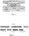
- FIG. 1 illustrates an exemplary high-level architecture of WARP-TDMAC.
- FIG. 2 illustrates an exemplary WARP-TDMAC frame structure.
- FIG. 3 illustrates pursuit statistics tables at the base station and the client, and the update process.
- FIG. 4 illustrates an example of the learning process.
- FIG. 5A illustrates the jamming resilience of directional transmission scheme with reference to an adversarial jamming setup.
- FIG. 5B illustrates the jamming resilience of directional transmission scheme with reference to a fixed location jammer.
- FIG. 5C illustrates the jamming resilience of directional transmission scheme with reference to a nomadic jammer.
- FIG. 6 illustrates exemplary reward estimates and selection counts.
- FIG. 7 illustrates the two-link interference measurement setup.
- FIG. 8 illustrates two-link interference scheduling for measurement.
- FIG. 9 illustrates interference reduction at different Tx power levels.
- FIG. 10 illustrates a downlink sum rate at different SINRs.
- FIG. 11 illustrates an exemplary network using a hybrid synchronization method.
- FIG. 12A illustrates an exemplary MAC-layer timestamping during message transport.
- FIG. 12B illustrates an exemplary PTP handshaking protocol for delay and offset estimation over Ethernet.
- FIG. 12C illustrates an exemplary Digital phase-locked loop (DPLL) for drift rate.
- DPLL Digital phase-locked loop
- FIG. 13A illustrates an exemplary measurement setup with four AP-client wireless links.
- FIG. 13B illustrates statistics over 5012 samples of PPS time displacements (1.5 hour).
- FIG. 13C illustrates statistics over 2026 samples of debug GPIO signal time displacements (2 min).
- FIG. 14 illustrates an exemplary method for adaptive pursuit learning as disclosed herein.
- FIG. 15 is an exemplary block diagram representing a general purpose computer system in which aspects of the methods and systems disclosed herein or portions thereof may be incorporated
- directional antennas Conventional use of directional antennas to address network densification may be considered in effective.
- the reasons may include: (i) the difficulty of integrating directional antennas into the existing wireless physical layer (PHY) and medium access control (MAC) stack of small cells, which typically use either Long-Term Evolution (LTE)-based or 802.11-based signaling for user data links, or (ii) the lack of robust antenna beam-steering (or beam selection) techniques that can cope well with the wireless channel's stochastic nature and dynamics in the operating environment of small cells.
- PHY physical layer
- MAC medium access control
- small cells typically constitute short-range (WiFi-like), low-power radio access nodes that are installed by consumers for better indoor voice and data services. Due to their shorter transmit-receive distance to users, small cells can greatly lower their transmit power and vary their signal bandwidth to achieve higher spectral efficiency and provide more opportunities for spatial reuse.
- nodes can also suppress unwanted emission and interference, thus effectively securing communications against eavesdroppers and jammers.
- directional antennas make possible the concept of a cognitive small-cell network-one that is capable of perceiving current network conditions and then adapting antenna beams accordingly to achieve its end goals.
- the present inventors have developed a cross-layer optimization approach nesting between PHY and MAC that is meant to support directional MAC protocols with synchronized channel access.
- the idea is to coordinate contention-free transmissions to occur simultaneously in an optimal way. Doing so usually requires synchronization among the nodes and is more suitable for cellular and small-cell access.
- ROMA also explores multi-beam adaptive array for simultaneous transmissions in the same time slot.
- Other conventional implementations propose DTRA for coordinated transmissions using steerable antennas, using a frame-based approach to neighbor discovery, hand-shaking, and reservation.
- a new MAC protocol called 2P has also been proposed for 802.11 mesh networks with long-distance links to enable simultaneous channel access over multiple hops. These approaches rely heavily on protocol coordination to schedule antenna directions and are usually not resilient to environmental changes.
- TDMA provides a straightforward framework for testing cognitive radios and smart antennas in a mobile network setting.
- Existing implementations of TDMA on SDRs either rely on commercial off-the-shelf (COTS) devices to meet strict timing and synchronization requirements, or resort to using high-latency SDR platforms which provide limited synchronization resolution (e.g., milliseconds in some observed cases.
- COTS commercial off-the-shelf
- high-latency SDR platforms which provide limited synchronization resolution (e.g., milliseconds in some observed cases.
- the few existing TDMA-style protocol implementations all fall short in operational capabilities.
- Ethernet backbone for synchronization
- IEEE Std 802.11-Part 11 Wireless LAN Medium Access Control (MAC) and Physical Layer (PHY) Specifications, 2012
- MAC Medium Access Control
- PHY Physical Layer
- the small-cell interference mitigation disclosed herein expands on the prior art efforts noted above and realizes a flexible testbed that can offer microsecond synchronization, as well as real-time scheduling in both time slots and antenna directions at millisecond slot granularity, without the need for a wired backbone.
- WLANs wireless local area networks
- DCF distributed coordination function
- QoS Quality of Service
- the next section develops the general adaptive pursuit learning solution for antenna state selection.
- the WARP-TDMAC testbed is described in the next section.
- the subsequent section (LINKPURSUIT PROTOCOL) describes the overall protocol including a practical implementation of the adaptive pursuit learning policy for antenna state selection in cognitive small-cell networks.
- the section after that (EXPERIMENTAL METHODOLOGY) discusses the methodology used in the experiments, and the final section (PERFORMANCE EVALUATION) presents the results, including the potential network sum-rate gains of the distributed directional antenna system over omnidirectional transmissions in a two-link interference scenario where both links are purposely scheduled to interfere in every data time slot.
- an agent operates in an environment with incomplete information and is repeatedly faced with K arms or choices in a sequence of trials.
- the agent selects to play an arm, for which it receives a stochastic reward R(t).
- the nature of the random reward for each arm is unknown to the agent a priori but is assumed to be independently drawn from a fixed, unknown distribution.
- MAB represents the trade-off between exploitation and exploration in that the agent chooses (i) maximizing expected profit using current knowledge of the environment, achieved by selecting the currently perceived best arm, or (ii) trying to learn more about the environment by exploring other arms to improve the quality of its decisions.
- the performance of a stationary MAB selection policy can be measured in terms of regret, defined as the policy's expected loss in reward when compared to the best possible outcome, obtained by selecting the (unknown) optimal choice.
- a family of ad-hoc learning methods are well-suited for the non-stationary bandit problem, including “ ⁇ -greedy action selection, softmax action selection, probability matching, and adaptive pursuit methods. Though these methods do not aim to balance exploration and exploitation in a sophisticated way, they also do not rely on strong assumptions (such as the assumption of i.i.d distribution of rewards generated by each arm), and they can be fine-tuned to produce near-optimal results.
- the antenna state selection process for cognitive small-cell links is formulated as a non-stationary MAB problem.
- the base stations can consist of all femtocells or a mix of an overlaid macrocell (the main BS) and auxiliary femtocells (the secondary base stations).
- Each BS serves a client for whom it would like to maximize the downlink throughput over a finite number of time slots.
- the base stations are greedy in terms of optimizing their own link throughput and do not cooperate with each other.
- co-channel interference is less predictable and more varied—as femtocell base stations can join or leave the network, as well as perform concurrent transmission randomly in time and possibly in different directions.
- the stations may also experience deliberate interference from hostile adversaries, thus further complicating the tasks of estimating the channel conditions and selecting the optimal antenna states.
- the following description focuses exclusively on downlink interference mitigation, but the learning framework presented can be generalized to handle the case of mixed downlink and uplink interference as well.
- A ( a 11 ... a 1 ⁇ N ⁇ ⁇ ⁇ a M ⁇ ⁇ 1 ... a MN ) .
- the BS and client through coordination can share information on their individually observed network conditions and jointly make a choice on their respective antenna states.
- the BS-client link After making a choice in time slot t, the BS-client link receives a numerical reward R(t) depending on the selected arm a ij in that time slot.
- An objective of the invention is to develop a robust antenna state selection strategy that can adapt well to the changes in the reward distributions while at the same time maximizing the expected reward output.
- the adaptive pursuit strategy is used due to its fast convergence toward the currently optimal solution, as noted by D. E. Koulouriotis and A. Xanthopoulos.
- the adaptive pursuit strategy is a probabilistic selection policy; it identifies at each time step the optimal selection probability P ij (t) for every antenna state a ij such that the expected cumulative reward is maximized at the end of the run.
- the arms' selection probabilities are specified in an operator probability matrix
- the adaptive pursuit algorithm maintains an operator quality matrix
- the adaptive pursuit method selects the operator a i*j* that currently has the maximum estimated reward Q i*j* (t), using a “winner take all” strategy: it increases the selection probability of the best arm toward P max while decreasing all other selection probabilities toward P min , 0 ⁇ P min ⁇ P max ⁇ 1.
- the adaptive pursuit policy is summarized for small-cell antenna state selection in exemplary Algorithm 1 below:
- P i*j* (t + 1) P i*j* (t) + ⁇ [P max ⁇ P i*j* (t)] 13: for i ⁇ 1 to M do 14: for j ⁇ 1 to N do 15: if ij ⁇ i*j* then 16: Pij(t + 1) ⁇ P ij (t) + ⁇ [P min ⁇ P ij (t)] 17: end if 18: end for 19: end for 20: t ⁇ t + 1 Advance time index 21: end while
- each individual AP-client link may employ an antenna orientation algorithm to autonomously steer the nodes' antenna beams in a way that maximizes (e.g., ideally improves) the link goodput.
- the antenna orientation process is formulated as a non-stationary multi-armed bandit problem and the adaptive pursuit method from reinforcement learning is applied to solve it. As an example, consider what happens at the beginning of a downlink time slot for a particular AP-client link: the AP is presented with M possible antenna states (orientations) for transmission, and the client has N antenna states for reception.
- the AP-client link After making a Tx and Rx orientation choice in time slot t, the AP-client link receives a numerical reward R(t), which is selected to be the (downlink) packet delivery ratio (PDR), depending on the selected antenna states.
- R(t) the (downlink) packet delivery ratio (PDR)
- PDR packet delivery ratio
- the goal of the link is to orient its constituent nodes' antennas in each time slot so that the expected cumulative reward is maximized (e.g., improved) at the end of the run.
- the adaptive pursuit strategy is a probabilistic selection policy; it identifies at each time step the reward-maximizing selection probability distribution over all antenna state combinations, and then proceeds to select the antenna states randomly according to that distribution.
- Adaptive pursuit has been shown to be well-suited for non-stationary environments, in which the reward generating processes associated with the antenna orientations do not remain the same over time. Furthermore, it can be fine-tuned to produce near optimal results.
- Initial experimental results show that our distributed directional antenna system is highly resilient to both deliberate and unintentional co-channel interference, maintaining at a minimum 60% PDRs for all network links under varying degrees of interference.
- the testbed, WARP-TDMAC is a directional cognitive small-cell testbed implemented on top of the WARP platform and targeted specifically for small-cell research.
- the inventors augment the FPGA-based, SISO, 802.11a/g standard-compliant physical layer with reconfigurable antennas and custom software layers to realize WARP-TDMAC.
- this platform a wide range of small-cell network services are provided such as the time synchronization between femto base stations and clients, resource scheduling, and programmable antenna directionality.
- FIG. 1 shows the high-level system architecture.
- Dynamic directionality is achieved through the use of compact pattern-reconfigurable antennas. These antennas provide inherent space and cost benefits by integrating multiple radiating elements on a single device, thereby enabling steerable directed beams with a reduced number of RF chains and lower processing overhead. These properties make reconfigurable antennas an ideal technology to be integrated into mobile devices and software-defined radio (SDR) testbeds.
- the reconfigurable antenna implementation is based on the planar reconfigurable Alford Loop antenna design, which can radiate in both an omnidirectional pattern and as well as in four directional beams at 90° separation with controllable beam widths.
- the antennas are integrated into the physical layer via a generic 16-pin GPIO header connecting directly to the antenna control circuitry and programmable via a shared register.
- the software framework includes a TDMA-based MAC layer and various upper-layer functions implemented using Microblaze cores.
- the MAC layer includes the time-critical mechanisms for physical layer control, time synchronization, time-frequency-space resource scheduling, packet buffering, and support for application-specific MAC code.
- the upper network layers handle auxiliary, non-time-critical functionalities, such as traffic generation, logging, and measurement routines. Synchronization is achieved following a Sync packet sent by a single “main” BS (a macrocell) at the beginning of each frame. This control packet signals all other network nodes slave base stations as well as clients to start their hardware timers to achieve a common time base.
- a software-polled technique in the MAC code is used to read the PHY-supplied microsecond time stamp of the start of Sync packet reception defined in 802.11 standards as the instant when the SIGNAL field is successfully decoded, and configure the hardware timer to interrupt at the beginning of the next time slot.
- this technique can achieve microsecond-level synchronization with high fidelity among all receiver nodes.
- a WARP-TDMAC frame starts with a Sync signal from the main BS, followed by a number of resource slots, and ends with a guard time slot. Each resource slot is further broken down into two time slots that can be used to send different packet types. This dual time-slot approach to forming the resource blocks is used to increase the granularity of resource scheduling thereby reducing protocol overhead.
- WARP-TDMAC supports four types of resource slots: Beacon, Ack, Data, and Empty.
- Beacon resource slots are reserved for a base station to send Beacon control packets to pass control information, link schedules, as well as link statistics.
- Ack resource slots are used by clients to send Ack packets to establish and maintain their presence to the BS.
- Each control packet occupies only a single time slot, freeing up the other time slot in the resource block for additional data transmission.
- Data slots are used for data transfer in the downlink or uplink directions.
- An example WARP-TDMAC frame structure in shown in FIG. 2 Currently the length of each time slot is set to 1.6 ms to provide extra slack for MAC protocol processing and DMA data transfer between the PHY buffers and MAC buffers.
- the WARP-TDMAC frame shown in FIG. 2 contains 16 Data resource slots and lasts for 59 ms including all processing delays.
- LinkPursuit is a practical adaptation of the antenna state selection algorithm presented above for real-time cognitive small-cell networks.
- the protocol is well suited for non-random access radio systems that operate in a time-slotted manner, as is typical in modern cellular networks that employ Long Term Evolution (LTE) technology.
- LTE Long Term Evolution
- LinkPursuit implements a distributed version of the adaptive pursuit algorithm to select the optimal antenna state at each time slot on a per-link (which BS-client pair) and per-direction (uplink or downlink) basis.
- the minimum selection probability Pmin can then be calculated using the constraint laid out above. These parameters are chosen based on practical observations of the protocol performance.
- every node in the network maintains two link-state tables for each of its unicast links: a Send table to derive the optimal antenna state for packet transmission to its link counterpart and a Receive table to derive the optimal antenna state for packet reception from that node.
- a Send table to derive the optimal antenna state for packet transmission to its link counterpart
- a Receive table to derive the optimal antenna state for packet reception from that node.
- the BS will use its Send table, and the client will use its Receive table to select the optimal antenna states at both ends in any given time slot.
- Each Send and Receive table contains two matrices: an antenna state selection probability matrix P, and an antenna state quality matrix Q which keeps track of the reward estimates for all state combinations. These matrices follow the same definitions laid out in the adaptive pursuit algorithm explained above.
- entries in the BS's send-table matrix contain the pursuit statistics for arm a ji which represents the combination of the BS's Tx antenna state i and the client's Rx antenna state j.
- the BS's Receive table is used in an uplink transmission and the corresponding matrix entries contain pursuit statistics for arm a ji which is the combination of the client's Tx antenna state j and BS's Rx antenna state i.
- a node can obtain the resource allocation schedules through Beacons and know when it is supposed to receive a packet. This scheduling information forms the basis for our reward metric based on packet delivery ratio (PDR): if a packet is not successfully received in a time slot in which a node is scheduled to receive, the node perceives a reward of 0. Otherwise, it receives a reward of 1.
- PDR packet delivery ratio
- the Receive table at the receiver node gets updated continuously following each transmission, whereas the Send table at the transmitter node is updated only when the receiver passes its most recent Receive table via a control packet.
- the Send table at the transmitter is a cached copy of the Receive table maintained online at the receiver. It is important to maintain coherency between the transmitter's Send table and receiver's Receive table, that is, not let them drift too far apart in time without periodic updates, as they independently supply the pursuit statistics for distributed selection of sending antenna state at the transmitter and receiving antenna state at the receiver.
- the client maintains real-time downlink pursuit statistics in its Receive table, and it passes this table in Ack packets to the BS, embedded in the packet payload, to update the BS's Send table.
- the BS passes the uplink pursuit statistics stored in its Receive table in the Beacon packet to the client to update the latter's Send table.
- the pursuit statistics tables and their update processes are shown in FIG. 3 . In FIG. 3 , the pursuit tables that maintain identical statistics at the opposite links have the same shading.
- LinkPursuit is a distributed protocol in that the transmitter and receiver can select their respective antenna states individually and not at the same time.
- the adaptive pursuit algorithm assumes that in each time slot, both the BS and client jointly select an arm a ij , the combination of Tx antenna state i and Rx antenna state j, from a joint probability distribution specified by the operator probability matrix P.
- this is not feasible in practice due to the prohibitive overhead of maintaining an up-to-date P at both link ends and jointly performing the selection in each time slot.
- P S (t) the pursuit marginal distribution of sending modes
- This decoupled antenna state selection process has multiple possible advantages, such as the following two.
- First it allows LinkPursuit to significantly minimize protocol overhead. Instead of simultaneously selecting Tx and Rx antenna states in each time slot, and then exchanging information over the air to carry out that joint decision at both link ends, the transmitter can preselect a send mode for that time slot randomly based on its local pursuit statistics and independent of the receiver's selected receive mode.
- the link receiver can still select a receive mode unilaterally given the chosen send mode in each time slot, using the most up-to-date Receive table to better track and reflect environmental variations.
- the base station selects send modes for all uplink and downlink Data packets in the frame since it has relevant pursuit statistics in both its downlink Send table and uplink Receive table at the beginning of frame.
- the BS then aggregates the preselected send mode information in the frame's link schedule and broadcasts to the entire network via its Beacon packet. Referencing the link schedule, a network-synchronized BS or client will be able to extract the preselected send mode for use when it is scheduled to transmit or receive. If scheduled to be the receiver in a given time slot, the node can select a receive mode knowing the scheduled send direction and its current Receive table. The scheduled send direction is also used to update the reward outcome in that time slot.
- LinkPursuit In addition to aggregating the preselected send modes with link schedules, LinkPursuit also puts this information in the actual packet data by augmenting the MAC header with an 8-bit send mode field which should be filled in by the transmitter prior to every packet transmission. This field is usually used when a client receives a data packet from the BS without any prior scheduling information-which happens when the client is not synchronized to the small-cell network. Using the send mode information obtained from the received packet as well as the receive mode that was used for reception, the client can still update its reward matrix and proceed to select the next Rx antenna state that may help re-establish synchronization with the network.
- the LinkPursuit learning protocol described thus far depends heavily on the reliability of the control channel which carries Sync, Beacon, and Ack messages. Transmission of control information is generally considered separate from the pursuit learning process, and thus probabilistic antenna state selection are not applied and the reward estimates associated with control packets are not updated. In practice, the control channel can be well separated in frequency from the data channel, making the optimal antenna states learned in the data channel less useful for control-packet delivery. However, for wireless protocols that employ in-band control messages such as 802.11 and LTE, and the experimental network, control packet delivery can benefit from the link statistics learned through data-packet transmissions.
- LinkPursuit optimizes control-packet delivery by selecting deterministically the currently perceived “optimal” send mode at the transmitter and receive mode at the receiver based on recent pursuit statistics obtained from data transmissions.
- This feature is implemented using a set of software hooks that execute immediately after sending or receiving a control packet. Specifically, after a pursuit-statistics table is exchanged via the control packet, the transmitter and receiver search through the joint distribution of antenna state selection probabilities stored in their Send and Receive tables and identify the antenna mode combination with the highest selection probability. The transmitter will then use this send mode and the receiver the corresponding receive mode for control-packet transmissions until the next exchange of the pursuit statistics.
- Special control-packet handling is also required in the exemplary embodiment: if the BS does not receive any uplink packet (Ack or Data) from the client in the frame, it assumes that there has been a problem with the Sync and Beacon packet deliveries and that the client has lost synchronization as a result. The BS will then update the downlink reward estimates in its Send table with zero for the send-receive mode combination (the arm) that was used to select the current control-packet send direction and attempt to reselect a new send mode for control packets. This process continues until the BS starts receiving uplink packets again and can update its Send table with the client's Receive table.
- the learning procedure implemented within LinkPursuit for optimal antenna state selection is summarized in FIG. 4 .
- This scheme explores an infeasible implementation of directionality wherein the performance outcomes of all antenna states are known prior to measurement.
- the measurement procedure sweeps through all available directional antenna state combinations: 16 for each individual link and 256 for the two-link network. Then, the optimal antenna configuration is determined using a posteriori knowledge as the one with highest downlink sum rate across all links.
- the ES scheme is perceived to have global knowledge of the channel conditions associated with all antenna states at the start of experiment, yet it lacks the adaptation capabilities of LinkPursuit. If there are no abrupt environmental changes that deteriorate the reward of a previously optimal antenna combination greatly, the ES scheme represents the upper performance bound for the LinkPursuit learning policy.
- the ESPT scheme periodically conducts an exhaustive search to determine the best antenna state in each measurement round. This introduces limited adaptivity (on the order of thousands of packets) in the exhaustive search process, allowing ESPT to react to major environmental changes.
- the total power radiated out of each Tx antenna is normalized to the Omni case. This usually requires additional power compensation for the directional antenna modes due to their greater return losses.
- the return loss of the RALA's omnidirectional mode is characterized to be ⁇ 9 dB (12.5% of the incident power) and that of its four directional modes to be ⁇ 3 dB on an average (50% of the incident power).
- the incident power sent to directional Tx antennas is increased by 75%. This is accomplished by compensating the directional antenna modes with an additional 2.5 dB in Tx RF gain over the omnidirectional case.
- the PDR and downlink throughput are measured at each client.
- Each data point presented in the plots conveys the results of one measurement round under a particular antenna setting.
- a round consists of 100 TDMA frames sent over the air with a fixed allocation of 33 downlink slots and 1 uplink slot per frame.
- For the ES scheme a measurement round is repeated for every possible antenna combination, and the optimal results are presented.
- Experiments are conducted on a relatively quiet, unused WiFi channel: 802.11 channel 14 at 2.484 GHz.
- the PHY settings are set fixed at QPSK with code rate 1/2, yielding a consistent PHY data rate of 12 Mbps.
- LinkPursuit's performance is evaluated through real-time over-the-air transmissions under both non-interfering single-link scenarios as well as scenarios involving two concurrent interfering links.
- co-channel interference can be unintentional, originating from other legitimate nodes in the vicinity, or deliberate, under control of an adversarial jammer.
- Directional antennas can significantly enhance the jamming resilience of a femtocell network by enabling beam-steering to place a null toward a jammer while minimally affecting the desired signal.
- a communication scenario under adversarial jamming may be considered where spread spectrum and error-correcting code are insufficient to combat the jammer.
- LinkPursuit's functionality is evaluated as an anti jam communications technique.
- FIG. 5A shows the network topology and possible jammer locations 1 and 2.
- an in-band, omnidirectional, and continuous jammer is employed to generate deliberate interference.
- the jammer is implemented using GNU Radio (http://gnuradio.org/redmine/projects/gnuradio) and the USRP N210 SDR platform (https://www.ettus.com/product.), based on an FPGA-modified jammer design described by D. Nguyen, et al., in “A Real-Time and Protocol-Aware Reactive Jamming Framework Built on Software-Defined Radios,” In Proc. of ACM SRIF '14, 2014.
- the jammer continuously generates a pseudorandom White Gaussian Noise (WGN) signal with 25 MHz bandwidth.
- WGN White Gaussian Noise
- the Tx output power of the USRP jammer is characterized at different RF gains also in dBm scale. This allows for fair comparison in terms of the transmit power ratio between the jammer and WARP radios during a jamming power sweep.
- a jam-to-signal Tx power ratio (JSR) sweep is performed from ⁇ 15 to 15 dB in increments of 3 dB and the resulting downlink PDRs of different transmission schemes are reported.
- the jammer is permitted to have mobility during operation. Specifically, both a fixed location jammer and a nomadic jammer that moves around looking for the most effective jamming location are considered.
- the fixed location jammer is randomly placed in the vicinity shown in FIG. 5A at Location 1 .
- the USRP jammer is moved from its initial position to a new location (denoted as Location 2 ) after a measurement round.
- the two locations are chosen to be of equidistance to the link receiver (e.g., the client) in order to minimize path loss effects.
- Another measurement is then conducted round at the new location and the results for the omni, random, and LinkPursuit schemes are averaged.
- the ES scheme measurement results of each antenna mode are averaged across two locations, and then the highest performing antenna mode is selected.
- the highest performance results from each measurement round are selected and averaged.
- the downlink PDRs of different directional transmission schemes are shown in FIG. 5B for the fixed location jammer scenario.
- the small-cell link experiences drastic drops in PDR as the jam-to-signal Tx power ratio increases from ⁇ 15 dB to 0 dB.
- Complete link outage occurs starting at a 3 dB JSR onward.
- the random selection scheme has substantially inferior performance to Omni, with a 40% PDR reduction at ⁇ 15 dB JSR. This performance gap decreases gradually with stronger interference, yielding only a 20% PDR loss at 0 dB JSR.
- the random scheme can maintain link traversal, albeit at very low PDR (less than 10%), up until 9 dB JSR, giving it a 6 dB anti-jam gain (in terms of link traversal) over Omni.
- LinkPursuit and the ES scheme are more resilient to jamming than Omni and Random.
- LinkPursuit maintains on an average over 60% PDR across the range of jamming powers, and its performance is tangential to that of ES. Except for two JSR cases at ⁇ 6 and ⁇ 3 dB, LinkPursuit's performance stays within 10% or even exceeds the ES scheme. For the occasions where LinkPursuit yields higher PDRs than ES, as observed at ⁇ 9, 9, and 15 dB JSRs, there are a few possible reasons.
- LinkPursuit responds to environmental changes at fine-grained granularity on per packet basis. If an optimal antenna mode becomes underperforming temporarily due to multipath effects, the algorithm quickly searches for another mode to use. In contrast, the ES scheme decides antenna configuration only once using global a posteriori performance knowledge of all available modes. This knowledge is obtained through an entire measurement round, with all transient environmental changes already assimilated. This implementation trait leads to a lack of adaptivity in ES, but it is a reasonable trade-off given the prohibitive cost of acquiring global performance knowledge and the short length of the measurement round. Thus, ES performance is optimal and upper-bounding LinkPursuit only if there has not been any change in channel conditions during the exhaustive sweep.
- LinkPursuit has a mechanism to optimize its control packet delivery (Syncs, Beacons, and Acks) through directionality, whereas all other schemes use the omnidirectional mode for them.
- Control packets are critical for all considered schemes, as link throughput is only accounted for the TDMA frames where the client is synchronized.
- Tx power scaling for control packets has also been enabled, e.g., sending them with maximum RF gain on WARP (31 dB). Nevertheless, when facing a high-power jammer, omnidirectional transmission of control packets can still suffer non-negligible losses, yielding abnormally low PDRs in the ES scheme.
- Using adaptive directional transmission for both control and data packets LinkPursuit can avoid TDMA protocol-dependent performance loss.
- FIG. 5C depicts the network's downlink PDR in the presence of a nomadic jammer moving from Location 1 to 2 during operation. It is observed that the Omni and Random schemes are largely oblivious to the jammer's mobility. Since the jammer moves at equal distances to the receiver/client, the difference in jamming effects between two jammer locations should not depend on channel attenuation. Rather, it embodies the multi-path variations and change in the angle of arrival of the jamming signal's line of sight (LOS) component. Neither Omni nor Random scheme makes an effort to be adaptive to these changes. As a result, the cumulative jamming effect on these schemes over multiple locations exhibits largely the same trend as in the fixed location jammer scenario.
- LOS line of sight
- LinkPursuit gives consistent PDR performance that tracks closely both ES and ESPT schemes. Furthermore, LinkPursuit adapts well to environmental changes and the jammer's mobility, yielding significantly higher PDRs than exhaustive search on multiple occasions (e.g., at ⁇ 12, ⁇ 9, and 9 dB JSRs). These results validate LinkPursuit's performance as an effective anti jam technique.
- the BS uses a reconfigurable antenna while the client operates with an omnidirectional dipole antenna.
- the real-time network operations are periodically frozen after 200 TDMA frames (6600 downlink packets) to inspect the pursuit statistics on the antenna adaptation process and induce artificial environmental changes, such as disabling (grounding control pin to reduce antenna gain) the currently perceived “optimal” Tx antenna mode.
- the verification procedure starts with all Tx directional modes active and then selectively disables among the remaining modes the current best Tx mode with the highest reward estimate after each 200-frame round
- FIG. 6 shows the reward estimates and selection counts of the four possible directional Tx antenna modes as perceived and selected by LinkPursuit at the end of each round. Since we used an omnidirectional antenna at the receiving client, we aggregate the performance metrics of each Tx mode across all Rx antenna modes and present them. We observe that during each measurement round, the number of times a Tx antenna mode is selected consistently tracks its reward estimates. The current highest-reward Tx mode is selected the majority of the time, and a small fraction of time is necessarily spent exploring the remaining modes for adaptation. Once a mode becomes suboptimal (or this case disabled), its reward is correctly updated within a single 200-frame round.
- Two BS-client links are set up within the same vicinity indoor with a distance of 10 m between the two BSes.
- the first BS is designated as the main BS, which will provide a common time base for other network nodes through its Sync packets.
- Each BS is serving its respective client (labeled as C 1 and C 2 ) that is situated 3 m away from itself in the same direction.
- the measurement topology is shown in FIG. 7 .
- Reconfigurable antennas are equipped at each node.
- IF real-time interference
- both BSes are scheduled to transmit concurrently to their respective client in every downlink DATA slot.
- FIG. 8 depicts this scheduling scheme. Except for the Beacon and Ack control packets which are orthogonalized in time, all other downlink transmissions will interfere.
- the signal-to-interfere-plus-noise ratio (SINR) at the receiver effectively determines the link outage probability. If both BSes transmit with similar power levels, depending on the topology, cross-interference can render one or both links unusable. As a result, random access MAC protocols such as IEEE 802.11 requires all other nodes in the vicinity to stay silent after detecting an active transmission. On the other hand, controlled access protocols employ dynamic resource allocation and site planning to mitigate co-channel interference.
- Directionality augments existing approaches to spatial reuse with the ability to conduct spatial filtering.
- a node can selectively transmit and receive signals to and from only certain desired directions. This can enhance the SINR in two ways: higher directivity gains in the direction of transmission, and lower interference powers from unwanted directions.
- An experiment is set up to study LinkPursuit's performance on a network scale under various levels of cross-link interference. Under the same topology shown in FIG. 7 , the transmit powers of both BSes are sequentially increased by adjusting their Tx RF gains. In the omni case, this has limited effect on the received SINRs since the relative power ratio between the two transmitters remains the same throughout. In directional cases, the Tx power sweep increasingly lessens the interference suppression capabilities of Rx directional antennas and intensifies the effects of beam orientation errors.
- FIG. 9 shows the downlink PDRs of the different transmission schemes across the range of Tx powers.
- LinkPursuit due to severe cross-link interference, only Link 2 can sustain a usable PDR.
- Client C 1 is completely dominated by the interfering signals from BS 2 , as can be inferred from the topology, and fails to decode its intended signals free of errors. Spatial reuse is therefore non-existent in the omni case.
- the sum rate (total throughput) of LinkPursuit consistently exceeds that of omni by 74% on average. Most of this sum rate improvement stems from the PDR increase of Link 1 —the weaker link in the omni case.
- LinkPursuit delivers usable PDRs for both BS-client links without hurting performance of the dominant link from the omni case. Furthermore, this spatial reuse gain of LinkPursuit persists across the range of transmission powers.
- LinkPursuit consistently delivers close to 90% of the sum rate achieved by the a posteriori exhaustive search scheme. The remaining performance gap is within reason for the implementation of LinkPursuit adopts a 90/10 exploitation-exploration ratio at all times. Further tuning of LinkPursuit parameters can potentially close down this performance gap, albeit at the cost of diminished environmental agility.
- the throughput of a link is highly dependent on its Tx power ratio to the interference source. Due to its uniform proximity to both BSes, client C 1 experiences stronger interference than C 2 in general, thereby yielding much lower SINR and throughput. This topology-induced loss can be compensated by increasing BS's Tx power with respect to BS 2 , but at the price of a corresponding decrease in link 2 ′s performance.
- the best-case scenario is hard to find, highly volatile, and often yields only a fraction of the maximum achievable throughput.
- LinkPursuit delivers well-balanced, close to optimal link throughputs across the range of power ratios. This capability greatly simplifies the task of interference management and ensures reliable quality of service for users.
- LinkPursuit is a novel learning protocol for distributed antenna state selection in directional cognitive small-cell networks.
- LinkPursuit incurs low over-head and adapts quickly to environmental changes through probabilistic selection at each time step.
- the experimental results confirm that coordinated directional transmission provides significant advantages over omnidirectional transmission in terms of resilience to deliberate or unintentional interference from other nodes.
- LinkPursuit achieves a 12 dB anti jam performance gain in link dropout prevention, and this efficacy degrades very little even when the jammer becomes mobile. It also achieves a 74% sum throughput improvement over omni when both base stations transmit concurrently at the same power levels and a 40% increase when they transmit with disproportionate power.
- LinkPursuit is not without limitation.
- Automated parameter tuning of LinkPursuit's operations in terms of adaptation rate a and learning rate (3 may be explored in alternative embodiments, which will enable adaptive exploration-exploitation ratios and can further improve performance. Effort is also warranted to consider the benefits of network cooperation in LinkPursuit. For example, the femtocell base stations can exchange pursuit statistics through the backbone to facilitate joint antenna mode selection across links.
- the achievable accuracy of this synchronization method is sub-microsecond (less than 1 us). This may be achieved using a combination of techniques: software timestamping, Ethernet-based synchronization protocol, digital phase-locked loop, or wireless reference broadcast synchronization.
- a hybrid wired-wireless time synchronization method targeting enterprise WLAN networks may enable deployments of distributed wireless PHY protocols.
- the method may synchronize network APs on the Ethernet backhaul using the IEEE 1588 Precise Time Protocol, while client devices (herein clients) are synchronized to their home AP via reference broadcast synchronization.
- This synchronization primitive was tested on WARP software-defined radios and evaluated through a microbenchmark involving a plurality of network links. The test results verified that the method achieves sub-microsecond synchronization accuracy among network nodes and therefore serves as an effective building block for protocol development.
- Fine-grained time synchronization in wireless local area networks poses a significant barrier toward realizing the benefits of recently proposed physical layer signaling techniques, including distributed MIMO, uplink multi-user MIMO, and network MIMO.
- WLANs wireless local area networks
- APs Access Points
- the cluster of APs or clients are required to maintain precise frequency and time synchronization to be centrally scheduled for joint transmission.
- Frequency synchronization allows the distributed transmitters to minimize frequency and phase offsets and appear as a coherent virtual MIMO transmitter.
- Time synchronization may be used to ensure that concurrent transmissions align their symbol boundaries within a tolerable precision, typically on the order of an OFDM cyclic prefix interval (e.g., 800 ns for 802.11a/g/n) to avoid inter-carrier (ICI) and inter-symbol interference (ISI).
- ICI inter-carrier
- ISI inter-symbol interference
- Disclosed herein a different approach and use is taken of the 802.11 TSF as the main timing source and sole over-the-air synchronization routine.
- Disclosed herein is an alternative hybrid time synchronization method in which the APs are synchronized on the Ethernet backbone using PTP with software timestamping, and the clients are synchronized to their home APs wirelessly through the reference beacon broadcasts supported by 802.11 TSF.
- FIG. 11 An exemplary hybrid synchronization architecture is depicted in FIG. 11 , with four major components as detailed below.
- MAC-layer timestamping High-accuracy time synchronization should have a robust timestamping method that minimizes transmission delay jitter during delay measurements.
- a software timestamping approach is taken, where the timestamps are drawn directly by the synchronization software stack during message processing.
- sync messages are timestamped by the MAC firmware after it has contended for channel access and is ready to start transmission of a buffered PHY packet.
- sync messages are timestamped following a Start-of-Frame Detect (SFD) signal issued by the PHY at a deterministic and repeatable point during message reception.
- SFD Start-of-Frame Detect
- Network APs can be synchronized with each other to achieve a common time base using the PTP over Ethernet.
- PTP incorporates a two-way handshaking protocol to estimate the message transmission delay as well as relative clock offset between two arbitrary nodes on the network, and then compensates for this offset by adjusting the local system clock. This procedure works based on the assumption that the message transmission delay is symmetrically invariant for both directions, which is a reasonable assumption for direct Ethernet links or a small LAN network. As shown in FIG.
- the offset is then used as input to adjust the slave AP's local MAC timer in order to compensate for the offset to master clock until the next re-synchronization instant.
- PTP treats the slave clock as a servo which may be driven by a proportional-integral-derivative (PID) controller based on the measured clock offset feedback.
- PID proportional-integral-derivative
- the protocol does not mandate specific implementations of such controller. How fast the slave clock can react to a sudden deviation in clock offset depends on the frequency of delay measurements and the behaviors of the clock adjustment servo.
- Timer adjustment for drift compensation also depends on the specific clock system. An tested prototype used a non-monotonic and time-adjustable clock timer. Based on the tests, it makes sense to use a Digital Phase-Locked Loop (DPLL) control structure, implemented purely in software and shown in FIG. 12C , to manage and compensate for clock drift on the slave APs.
- DPLL Digital Phase-Locked Loop
- the system uses the current clock offset estimate to the master AP and produces a timer phase adjustment in terms of ticks, which can be positive (tuning forward) or negative (backward), to apply directly on the current slave timer value. It incorporates a loop filter that tracks the quality of input offset estimates on the proportional branch and the estimated drift rate on the integral branch.
- the loop gain parameters ⁇ and ⁇ determine the filter's damping characteristics and are tuned periodically in software during the acquisition stage (e.g., when a slave AP first comes online) to put the clock offset to within a small displacement.
- the gains settle to their steady-state values when the system enters the tracking stage after a certain number of tuning rounds.
- Another important design parameter is the required re-synchronization interval to periodically perform PTP timestamp handshaking. This value is subject to the desired synchronization precision, and was set to 50 ms in our tests.
- 802.11 TSF may be relied upon to synchronize clients to their associated AP.
- This method incorporates a time-adjustable WLAN MAC timer and a Reference Broadcast Synchronization (RBS) scheme, wherein clients are required to update their MAC timer upon receiving the beacon signals broadcasted periodically by all APs.
- RBS Reference Broadcast Synchronization
- changes to the 802.11 TSF operations are disclosed.
- indeterministic channel contention time can incur large jitter in the beacon transmission delay. This can be addressed by (i) moving beacon broadcasts to the contention-free periods of 802.11 MAC, or (ii) employing a time-division multiple access (TDMA) MAC protocol to guarantee channel access for beacon transmissions.
- TDMA time-division multiple access
- the clients may adjust their MAC timers based on the current clock offset, which may be estimated from the beacon's send and receive timestamps and the transmission delay.
- the total transmission delay (consisting of propagation and processing time) is therefore deterministic and invariant.
- we empirically measure this beacon transmission delay by observing the debug traces of both timestamping events on an oscilloscope.
- a simple two-way timestamp exchange at association time should suffice to derive the near-constant AP-client beacon message delay.
- the client node is considered synchronized with its home AP and may use the common time base for TDMA scheduling. For a typical WLAN, this technique may achieve microsecond-level synchronization with high precision among all network nodes.
- FIG. 13A is an exemplary measurement setup in which the APs are numbered from 1301 through 1304, and each AP may service as a single client from its BSS.
- PPS pulse per second
- TDMA channel access on the network nodes and implement a one-bit debug GPIO signal that is raised immediately after a 1.6 ms contention-free beacon broadcast period at the beginning of each 60 ms TDMA frame.
- Both the PPS and debug GPIO signals may be routed to the physical debug header onboard each WARP node and subsequently observed on a 20-GSPS oscilloscope.
- the synchronization accuracy of the network APs via the Ethernet backbone is depicted in FIG. 13B for over 5000 samples (1.5 hour period) of the time displacements between the PPS signals of AP 1302 -AP 1304 and AP 1301 's.
- the PTP protocol works well to synchronize the slave APs within 150 ns accuracy of the main AP.
- end-to-end measurement may be run to evaluate the synchronization accuracy among clients in the network.
- FIG. 13C shows the measurement results over 2026 TDMA frames in approximately 2 minutes.
- the hybrid synchronization method performs amicably to keep all network clients in tight timing agreement despite having geographically distributed timing sources.
- the standard deviations of the sync errors are within 100 ns for the clients and the error means are close to zero for the client 1312 -client 1311 and client 1313 -client 1311 client pairs.
- FIG. 14 illustrates an exemplary method for adaptive pursuit learning as disclosed herein.
- AP 1401 e.g., a master AP
- the schedule specifies the send and receive nodes, as well as the send antenna direction, for time slots in the frame.
- AP 1401 may also start a timing source server over the Ethernet interface to provide timing information to other APs connecting to the backbone.
- AP 1402 (e.g., slave AP) may comen online and start communicating with AP 1402 via the Ethernet backbone.
- AP 1402 runs the AP-to-AP synchronization mechanism described above to obtain a common time base with AP 1401 .
- AP 1402 may start its initialization process, such as reset learning statistics, compute link schedules, and start the TDMA frame.
- Each frame may include a number of time slots for transmission.
- APs synchronously broadcast their link schedules (through beacon control packets) to their clients in the vicinity.
- the link schedules carry the transmission information to be executed in the frame.
- Client 1403 (and Client 1404 ) (two example clients) follow the link schedules in each time slot.
- Client 1403 and client 1404 make decisions on receive antenna direction based on their current learning statistics and may obtain the outcome of those decisions (e.g., whether a packet is successfully received in that time slot), and update the learning statistics for the selected send-receive antenna combination. This process repeats for all downlink slots in the TDMA frame.
- step 1416 A in an ACK slot of each TDMA frame, the clients send aan cknowledgment packet, which also carry their current downlink pursuit statistics, to their respective APs for link schedule computation in the next TDMA frame.
- This step 1416 A/ 1416 B happens synchronously for clients in the network.
- step 1417 A and 1417 B at the end of each TDMA frame, APs review the current pursuit statistics of sservicing clients to compute the link schedule of the next frame. This step happens synchronously for all APs.
- the APs determine if convergence may be achieved or not (whether the links can be packed together harmonically), or some links must yield and defer transmissions.
- the APs e.g., AP 1401 and AP 1402
- the APs may coordinate with each other via the Ethernet backhaul. APs are allowed to be greedy and optimize only their own links without the need to coordinate with other APs.
- step 1418 e.g., step 1419
- AP 1401 and AP 1042 and Client 1403 and Client 104 may repeat steps 1414 A/B- 1418 .
- a further step may include delivering link schedules from the access points to said clients once time synchronization is achieved and providing up/downlink wireless data transmissions in a scheduled time slot.
- a further step may include spatially packing multiple directional access point—client links and using machine learning techniques to orient antenna beams of said nodes.
- There may be further step may include coordinating the access points with each other over said Ethernet backbone to exchange learning statistics and avoid potential oscillation in finding an equilibrium for network-wide antenna configuration.
- MAC medium access control
- the adaptive pursuit algorithm may use a link packet delivery ratio as a reward metric that is optimized during antenna state selection. All combinations in this paragraph (including the removal or addition of steps) are contemplated as disclosed herein.
- FIG. 15 and the following discussion are intended to provide a brief general description of a suitable computing environment in which the methods and systems disclosed herein and/or portions thereof may be implemented.
- the methods and systems disclosed herein may be described in the general context of computer-executable instructions, such as program modules, being executed by a computer, such as a client workstation, server, personal computer, or mobile computing device such as a smartphone.
- program modules include routines, programs, objects, components, data structures and the like that perform particular tasks or implement particular abstract data types.
- the methods and systems disclosed herein and/or portions thereof may be practiced with other computer system configurations, including hand-held devices, multi-processor systems, microprocessor-based or programmable consumer electronics, network PCs, minicomputers, mainframe computers and the like.
- the methods and systems disclosed herein may also be practiced in distributed computing environments where tasks are performed by remote processing devices that are linked through a communications network.
- program modules may be located in both local and remote memory storage devices.
- FIG. 15 is a block diagram representing a general purpose computer system in which aspects of the methods and systems disclosed herein and/or portions thereof may be incorporated.
- the exemplary general purpose computing system includes a computer 1520 or the like, including a processing unit 1521 , a system memory 1522 , and a system bus 1523 that couples various system components including the system memory to the processing unit 1521 .
- the system bus 1523 may be any of several types of bus structures including a memory bus or memory controller, a peripheral bus, and a local bus using any of a variety of bus architectures.
- the system memory includes read-only memory (ROM) 1524 and random access memory (RAM) 1525 .
- ROM read-only memory
- RAM random access memory
- a basic input/output system 1526 (BIOS) containing the basic routines that help to transfer information between elements within the computer 1520 , such as during start-up, is stored in ROM 1524 .
- the computer 1520 may further include a hard disk drive 1527 for reading from and writing to a hard disk (not shown), a magnetic disk drive 1528 for reading from or writing to a removable magnetic disk 1529 , and an optical disk drive 1530 for reading from or writing to a removable optical disk 1531 such as a CD-ROM or other optical media.
- the hard disk drive 1527 , magnetic disk drive 1528 , and optical disk drive 1530 are connected to the system bus 1523 by a hard disk drive interface 1532 , a magnetic disk drive interface 1533 , and an optical drive interface 1534 , respectively.
- the drives and their associated computer-readable media provide non-volatile storage of computer readable instructions, data structures, program modules and other data for the computer 1520 . As described herein, computer-readable media is an article of manufacture and thus not a transient signal.
- exemplary environment described herein employs a hard disk, a removable magnetic disk 1529 , and a removable optical disk 1531
- other types of computer readable media which can store data that is accessible by a computer may also be used in the exemplary operating environment.
- Such other types of media include, but are not limited to, a magnetic cassette, a flash memory card, a digital video or versatile disk, a Bernoulli cartridge, a random access memory (RAM), a read-only memory (ROM), and the like.
- a number of program modules may be stored on the hard disk, magnetic disk 1529 , optical disk 1531 , ROM 1524 or RAM 1525 , including an operating system 1535 , one or more application programs 1536 , other program modules 1537 and program data 1538 .
- a user may enter commands and information into the computer 1520 through input devices such as a keyboard 1540 and pointing device 1542 .
- Other input devices may include a microphone, joystick, game pad, satellite disk, scanner, or the like.
- serial port interface 1546 that is coupled to the system bus, but may be connected by other interfaces, such as a parallel port, game port, or universal serial bus (USB).
- a monitor 1547 or other type of display device is also connected to the system bus 1523 via an interface, such as a video adapter 1548 .
- a computer may include other peripheral output devices (not shown), such as speakers and printers.
- the exemplary system of FIG. 15 also includes a host adapter 1555 , a Small Computer System Interface (SCSI) bus 1556 , and an external storage device 1562 connected to the SCSI bus 1556 .
- SCSI Small Computer System Interface
- the computer 1520 may operate in a networked environment using logical connections to one or more remote computers, such as a remote computer 1549 .
- the remote computer 1549 may be a personal computer, a server, a router, a network PC, a peer device or other common network node, and may include many or all of the elements described above relative to the computer 1520 , although only a memory storage device 1550 has been illustrated in FIG. 15 .
- the logical connections depicted in FIG. 15 include a local area network (LAN) 1551 and a wide area network (WAN) 1552 .
- LAN local area network
- WAN wide area network
- Such networking environments are commonplace in offices, enterprise-wide computer networks, intranets, and the Internet.
- the computer 1520 When used in a LAN networking environment, the computer 1520 is connected to the LAN 1551 through a network interface or adapter 1553 . When used in a WAN networking environment, the computer 1520 may include a modem 1554 or other means for establishing communications over the wide area network 1552 , such as the Internet.
- the modem 1554 which may be internal or external, is connected to the system bus 1523 via the serial port interface 1546 .
- program modules depicted relative to the computer 1520 may be stored in the remote memory storage device. It will be appreciated that the network connections shown are exemplary and other means of establishing a communications link between the computers may be used.
- Computer 1520 may include a variety of computer readable storage media.
- Computer readable storage media can be any available media that can be accessed by computer 1520 and includes both volatile and nonvolatile media, removable and non-removable media.
- Computer readable media may comprise computer storage media and communication media.
- Computer storage media include both volatile and nonvolatile, removable and non-removable media implemented in any method or technology for storage of information such as computer readable instructions, data structures, program modules or other data.
- Computer storage media include, but are not limited to, RAM, ROM, EEPROM, flash memory or other memory technology, CD-ROM, digital versatile disks (DVD) or other optical disk storage, magnetic cassettes, magnetic tape, magnetic disk storage or other magnetic storage devices, or any other medium which can be used to store the desired information and which can be accessed by computer 1520 . Combinations of any of the above should also be included within the scope of computer readable media that may be used to store source code for implementing the methods and systems described herein. Any combination of the features or elements disclosed herein may be used in one or more examples.
Landscapes
- Engineering & Computer Science (AREA)
- Computer Networks & Wireless Communication (AREA)
- Signal Processing (AREA)
- Theoretical Computer Science (AREA)
- Physics & Mathematics (AREA)
- Software Systems (AREA)
- General Physics & Mathematics (AREA)
- General Engineering & Computer Science (AREA)
- Evolutionary Computation (AREA)
- Data Mining & Analysis (AREA)
- Computing Systems (AREA)
- Artificial Intelligence (AREA)
- Mathematical Physics (AREA)
- Medical Informatics (AREA)
- Computer Vision & Pattern Recognition (AREA)
- Environmental & Geological Engineering (AREA)
- Mathematical Analysis (AREA)
- Probability & Statistics with Applications (AREA)
- Algebra (AREA)
- Computational Mathematics (AREA)
- Mathematical Optimization (AREA)
- Pure & Applied Mathematics (AREA)
- Quality & Reliability (AREA)
- Mobile Radio Communication Systems (AREA)
Abstract
Description
is the maximum (but unknown) mean among all reward distributions of arms; and ni(l) is the number of times arm i has been played up to time slot l. E[·] is the expectation operator.
or the current time step. Apparently, the first term in this quantity favors exploitation (play the arm with the best empirical reward to date), whereas the second term enforces exploration (all arms must be played infinitely many times as the time index l→∞). It can be observed that UCB1 and its variants, UCB2 and UCB-Tuned by Auer et al. use deterministic operator selection rules to bound the regret growth rate. However, under a deterministic selection policy, the time gap between two selections of some under-optimal arm increases exponentially over time. Over a finite horizon—i.e., the MAB task only lasts for a finite number of trials—the number of times an under-optimal arm is selected can be arbitrarily low.
For practicality, it is further assumed that the BS and client through coordination can share information on their individually observed network conditions and jointly make a choice on their respective antenna states. After making a choice in time slot t, the BS-client link receives a numerical reward R(t) depending on the selected arm aij in that time slot. In this description, PDR is used as the reward metric and it is assumed that the reward in time slot t for some selected antenna state aij is drawn from an unknown Bernoulli distribution: with probability μij(t) the packet is received successfully, that is, R(t)=1; otherwise, R(t)=0. Further, the reward distribution mean for each arm aij changes over time, that is, ∃t1, t2∈[1, T] and t1≠t2, such that μij(t1)≠μij(t2).
where 0≤Pij(t)≤1 and Σi,jPij(t)=1. Toward this reward maximization goal, the adaptive pursuit algorithm maintains an operator quality matrix
that keeps a running estimate of the reward for each arm. Whenever arm (antenna state) aij is played, its current reward estimate Qij(t) is updated with the corresponding received reward R(t) using an exponential, weighted averaging mechanism as:
Q ij(t+1)=(1−α)Q ij(t)+αR(t),
where the adaptation rate α, 0<α≤1 discounts the past reward estimates obtained for arm aij.
P i*j*(t+1)=P i*j*(t)+β[P max −P i*j*(t)],
for i*j*=argmaxij {Q(t)}
P ij(t+1)=P ij(t)+β[P min −P ij(t)], ∀ij≠i*j*
under the constraint Pmax=1−(M·N−1)Pmin. The learning rate β determines the convergence speed and accuracy, and the constraint ensures that if Σi,jPij(t)=1, the sum of the updated selection probabilities equals one in the next time step. The adaptive pursuit policy is summarized for small-cell antenna state selection in
| |
| Adaptive Pursuit Selection Policy [9] |
| Input: M, N, Pmin, α, β |
| Output:
|
|
| 1: | Pmax ← 1 − (M · N − 1) Pmin; t ← 0 |
| 2: | for i ← 1 to M do | |
| 3: | for j ← 1 to N do |
| 4: |
|
| 5: | end for |
| 6: | end for |
| 7: | while NOTTERMINATED( ) do | |
| 8: |
|
| 9: |
|
|
| 10: |
|
| 11: | i*j* = ARGMAXij (Q(t + 1)) | |
| 12: | Pi*j*(t + 1) = Pi*j* (t) + β[Pmax − Pi*j*(t)] |
| 13: | for i ← 1 to M do |
| 14: | for j ← 1 to N do |
| 15: | if ij ≠ i*j* then |
| 16: | Pij(t + 1) ← Pij(t) + β[Pmin − Pij(t)] |
| 17: | end if |
| 18: | end for |
| 19: | end for |
| 20: | t ← |
|
| 21: | end while |
Pr(S∩R)=Pr(S)·Pr(R|S)
where S and R are random variables representing the Tx and Rx antenna states, respectively. As a result, the Tx antenna state in time slot t is selected randomly according to the pursuit marginal distribution of sending modes PS(t), specified as:
The Rx antenna state is then selected from the pursuit conditional distribution of receive modes given a preselected sending mode i(1≤i≤M), specified as:
delay=((t2−t1)+(t4−t3))/2; offset=((t2−t1)−(t4−t3))/2
Claims (20)
Priority Applications (1)
| Application Number | Priority Date | Filing Date | Title |
|---|---|---|---|
| US15/720,951 US10694526B2 (en) | 2016-09-30 | 2017-09-29 | Adaptive pursuit learning method to mitigate small-cell interference through directionality |
Applications Claiming Priority (2)
| Application Number | Priority Date | Filing Date | Title |
|---|---|---|---|
| US201662402671P | 2016-09-30 | 2016-09-30 | |
| US15/720,951 US10694526B2 (en) | 2016-09-30 | 2017-09-29 | Adaptive pursuit learning method to mitigate small-cell interference through directionality |
Publications (2)
| Publication Number | Publication Date |
|---|---|
| US20180098330A1 US20180098330A1 (en) | 2018-04-05 |
| US10694526B2 true US10694526B2 (en) | 2020-06-23 |
Family
ID=61758614
Family Applications (1)
| Application Number | Title | Priority Date | Filing Date |
|---|---|---|---|
| US15/720,951 Active - Reinstated US10694526B2 (en) | 2016-09-30 | 2017-09-29 | Adaptive pursuit learning method to mitigate small-cell interference through directionality |
Country Status (1)
| Country | Link |
|---|---|
| US (1) | US10694526B2 (en) |
Cited By (2)
| Publication number | Priority date | Publication date | Assignee | Title |
|---|---|---|---|---|
| US20210319098A1 (en) * | 2018-12-31 | 2021-10-14 | Intel Corporation | Securing systems employing artificial intelligence |
| US20230109333A1 (en) * | 2021-10-01 | 2023-04-06 | Ewha University - Industry Collaboration Foundation | Method Of Building Ad-Hoc Network Of Wireless Relay Node And Ad-Hoc Network System |
Families Citing this family (38)
| Publication number | Priority date | Publication date | Assignee | Title |
|---|---|---|---|---|
| JPWO2018150474A1 (en) * | 2017-02-14 | 2019-12-12 | Quadrac株式会社 | Apparatus and system |
| CN116776964B (en) | 2017-04-14 | 2025-11-25 | 渊慧科技有限公司 | Methods, program products, and storage media for distributed reinforcement learning |
| SG11202000760SA (en) | 2017-07-26 | 2020-02-27 | Aviat Networks Inc | Distributed radio transparent clock over a wireless network |
| US10868623B2 (en) * | 2017-07-26 | 2020-12-15 | Aviat U.S., Inc. | Airframe timestamping technique for point-to-point radio links |
| CN107832439B (en) * | 2017-11-16 | 2019-03-08 | 百度在线网络技术(北京)有限公司 | Method, system and the terminal device of more wheel state trackings |
| WO2019148174A2 (en) * | 2018-01-29 | 2019-08-01 | Illume Health LLC | Method and system for personalized injection and infusion site optimization |
| WO2019151984A1 (en) * | 2018-01-30 | 2019-08-08 | Google Llc | Dynamic placement of computation sub-graphs |
| CN109327252B (en) * | 2018-10-30 | 2021-09-24 | 电子科技大学 | An online learning beam selection method based on contact context |
| US11184232B2 (en) * | 2018-11-26 | 2021-11-23 | Eagle Technology, Llc | Radio frequency (RF) communication system providing enhanced RF equipment configuration updates for mobile vehicles based upon reward matrices and related methods |
| KR102288785B1 (en) | 2019-01-17 | 2021-08-13 | 어드밴스드 뉴 테크놀로지스 씨오., 엘티디. | Sampling Schemes for Strategic Search in Strategic Interactions Between Parties |
| MY196331A (en) * | 2019-01-17 | 2023-03-24 | Advanced New Technologies Co Ltd | Strategy Searching In Strategic Interaction Between Parties |
| CN109919615B (en) * | 2019-03-01 | 2021-04-02 | 上海分布信息科技有限公司 | Cross-chain data interaction method and system based on block chain |
| SG11202002910RA (en) | 2019-05-15 | 2020-12-30 | Advanced New Technologies Co Ltd | Determining action selection policies of an execution device |
| SG11202002890QA (en) | 2019-05-15 | 2020-12-30 | Advanced New Technologies Co Ltd | Determining action selection policies of an execution device |
| CN112292696B (en) | 2019-05-15 | 2024-07-16 | 创新先进技术有限公司 | Method and apparatus for determining action selection policy of execution device |
| CN112292699B (en) | 2019-05-15 | 2024-09-27 | 创新先进技术有限公司 | Method and apparatus for determining action selection policy of execution device |
| US11516757B2 (en) * | 2019-06-07 | 2022-11-29 | Intel Corporation | Multi-access point collaboration in wireless communications |
| EP3758249A1 (en) | 2019-06-27 | 2020-12-30 | Nokia Technologies Oy | Adaptive antenna arrangements for cellular communication system |
| US11513520B2 (en) * | 2019-12-10 | 2022-11-29 | International Business Machines Corporation | Formally safe symbolic reinforcement learning on visual inputs |
| SG11202010204TA (en) | 2019-12-12 | 2020-11-27 | Alipay Hangzhou Inf Tech Co Ltd | Determining action selection policies of an execution device |
| WO2020098822A2 (en) | 2019-12-12 | 2020-05-22 | Alipay (Hangzhou) Information Technology Co., Ltd. | Determining action selection policies of an execution device |
| SG11202010721QA (en) | 2019-12-12 | 2020-11-27 | Alipay Hangzhou Inf Tech Co Ltd | Determining action selection policies of execution device |
| US11843434B2 (en) * | 2020-03-26 | 2023-12-12 | Drexel University | Millimeter wave coarse beamforming using outband sub-6GHz reconfigurable antennas |
| CN111446999A (en) * | 2020-03-26 | 2020-07-24 | 上海无线通信研究中心 | Position-assisted beam alignment method and system based on multi-arm bandit |
| CN112437690B (en) * | 2020-04-02 | 2024-07-12 | 支付宝(杭州)信息技术有限公司 | Method and apparatus for determining action selection policy of execution device |
| CN112533681B (en) | 2020-04-02 | 2024-07-12 | 支付宝(杭州)信息技术有限公司 | Determine the action selection policy for the execution device |
| TWI741619B (en) * | 2020-05-26 | 2021-10-01 | 國立中山大學 | Method of parameter estimation for a mimo system based on deep learning |
| CN111934786B (en) * | 2020-07-30 | 2021-12-24 | 桂林理工大学 | Signal concealment anti-interference method and device based on deep reinforcement learning |
| CN112328959B (en) * | 2020-10-14 | 2023-04-11 | 哈尔滨工程大学 | Multi-target tracking method based on adaptive extended Kalman probability hypothesis density filter |
| US11888569B2 (en) * | 2020-11-13 | 2024-01-30 | Intelsat US LLC | Communication system for multiple-input-multiple-output (MIMO) communication with aerial platform |
| US11903017B2 (en) * | 2021-03-03 | 2024-02-13 | Qualcomm Incorporated | Wireless network configuration for low-latency applications |
| CN113452470B (en) * | 2021-05-06 | 2022-06-17 | 浙江工业大学 | Signal power optimization method for wireless energy supply communication network |
| CN113207129B (en) * | 2021-05-10 | 2022-05-20 | 重庆邮电大学 | Dynamic spectrum access method based on confidence interval upper bound algorithm and DRL algorithm |
| CN113472472B (en) * | 2021-07-07 | 2023-06-27 | 湖南国天电子科技有限公司 | Multi-cell collaborative beam forming method based on distributed reinforcement learning |
| US12127147B2 (en) * | 2021-11-19 | 2024-10-22 | Ufi Space Co., Ltd. | Synchronization correction method, master device and slave device |
| US12413358B2 (en) * | 2022-05-26 | 2025-09-09 | Microsoft Technology Licensing, Llc | Determining reference signal transmission times |
| US12309085B2 (en) * | 2022-08-19 | 2025-05-20 | Qualcomm Incorporated | Null tones adaptation using reinforcement learning |
| CN116249169B (en) * | 2023-03-07 | 2025-11-25 | 南京邮电大学 | A Method and System for Selecting Access Modes in Wireless Mesh Networks Based on TimeGAN and Multi-Armed Slot Machines |
Citations (3)
| Publication number | Priority date | Publication date | Assignee | Title |
|---|---|---|---|---|
| US20130095774A1 (en) * | 2011-09-08 | 2013-04-18 | Drexel University | Method for selecting state of a reconfigurable antenna in a communication system via machine learning |
| US20160157195A1 (en) * | 2014-11-27 | 2016-06-02 | Mediatek Inc. | Collaborative OBSS Interference Mitigation for Wireless Communication Systems |
| US20170013572A1 (en) * | 2015-07-09 | 2017-01-12 | Google Inc. | System for network discovery and synchronization |
-
2017
- 2017-09-29 US US15/720,951 patent/US10694526B2/en active Active - Reinstated
Patent Citations (3)
| Publication number | Priority date | Publication date | Assignee | Title |
|---|---|---|---|---|
| US20130095774A1 (en) * | 2011-09-08 | 2013-04-18 | Drexel University | Method for selecting state of a reconfigurable antenna in a communication system via machine learning |
| US20160157195A1 (en) * | 2014-11-27 | 2016-06-02 | Mediatek Inc. | Collaborative OBSS Interference Mitigation for Wireless Communication Systems |
| US20170013572A1 (en) * | 2015-07-09 | 2017-01-12 | Google Inc. | System for network discovery and synchronization |
Non-Patent Citations (34)
Cited By (4)
| Publication number | Priority date | Publication date | Assignee | Title |
|---|---|---|---|---|
| US20210319098A1 (en) * | 2018-12-31 | 2021-10-14 | Intel Corporation | Securing systems employing artificial intelligence |
| US12346432B2 (en) * | 2018-12-31 | 2025-07-01 | Intel Corporation | Securing systems employing artificial intelligence |
| US20230109333A1 (en) * | 2021-10-01 | 2023-04-06 | Ewha University - Industry Collaboration Foundation | Method Of Building Ad-Hoc Network Of Wireless Relay Node And Ad-Hoc Network System |
| US12294868B2 (en) * | 2021-10-01 | 2025-05-06 | EWHA University—Industry Collaboration Foundation | Method of building ad-hoc network of wireless relay node and ad-hoc network system |
Also Published As
| Publication number | Publication date |
|---|---|
| US20180098330A1 (en) | 2018-04-05 |
Similar Documents
| Publication | Publication Date | Title |
|---|---|---|
| US10694526B2 (en) | Adaptive pursuit learning method to mitigate small-cell interference through directionality | |
| US11838862B2 (en) | Coordinated target wake time (TWT) service for localized wireless neighborhoods | |
| Liu et al. | DIRC: Increasing indoor wireless capacity using directional antennas | |
| Takai et al. | Directional virtual carrier sensing for directional antennas in mobile ad hoc networks | |
| US9179495B1 (en) | Implementing “all wireless” network over WiFi equipment using “scheduled TDMA” | |
| Monks et al. | A power controlled multiple access protocol for wireless packet networks | |
| CN114651397B (en) | Coordinated beam refinement and coordinated beam failure recovery | |
| Bao et al. | Transmission scheduling in ad hoc networks with directional antennas | |
| US20110021153A1 (en) | Centralized cross-layer enhanced method and apparatus for interference mitigation in a wireless network | |
| Laufer et al. | A cross-layer backpressure architecture for wireless multihop networks | |
| CN109565641A (en) | A system and method for beacon interval adaptation | |
| US11057842B2 (en) | Interference aware transmission power control method and device for IEEE 802.11 based wireless network with nodes having a directional antenna | |
| Tong et al. | MRA-MAC: A multi-radio assisted medium access control in terahertz communication networks | |
| Buratti et al. | Comparing MAC protocols for industrial IoT using Terahertz communications | |
| Bayhan et al. | Coexistence gaps in space: Cross-technology interference-nulling for improving LTE-U/WiFi coexistence | |
| Wang et al. | Simultaneous wireless information and power transfer in UAV-assisted cellular IoT networks | |
| Song et al. | A survey of single and multi-hop link schedulers for mmWave wireless systems | |
| Subramanian et al. | Topology control protocol using sectorized antennas in dense 802.11 wireless networks | |
| Xu et al. | A novel link scheduling strategy for concurrent transmission in mmWave WPANs based on beamforming information | |
| Chaudhari et al. | Femto-to-femto (F2F) communication: The next evolution step in 5G wireless backhauling | |
| KR101579813B1 (en) | Method for topology control using sectorized antennas in wireless networks | |
| CN117063414A (en) | Preconfigured Uplink Resource (PUR) verification in non-terrestrial networks | |
| Panno et al. | On mm Wave radio network planning based on a centralized access control | |
| Wang et al. | Coordinated fair resource sharing in dense indoor wireless networks | |
| Paatelma et al. | Reinforcement learning system to mitigate small-cell interference through directionality |
Legal Events
| Date | Code | Title | Description |
|---|---|---|---|
| FEPP | Fee payment procedure |
Free format text: ENTITY STATUS SET TO UNDISCOUNTED (ORIGINAL EVENT CODE: BIG.); ENTITY STATUS OF PATENT OWNER: SMALL ENTITY |
|
| FEPP | Fee payment procedure |
Free format text: ENTITY STATUS SET TO SMALL (ORIGINAL EVENT CODE: SMAL); ENTITY STATUS OF PATENT OWNER: SMALL ENTITY |
|
| AS | Assignment |
Owner name: CENTRE FOR WIRELESS COMMUNICATIONS, UNIVERSITY OF OULU, FINLAND Free format text: ASSIGNMENT OF ASSIGNORS INTEREST;ASSIGNORS:PAATELMA, ANTON;SAARNISAARI, HARRI;SIGNING DATES FROM 20161025 TO 20161127;REEL/FRAME:044163/0141 Owner name: CENTRE FOR WIRELESS COMMUNICATIONS, UNIVERSITY OF Free format text: ASSIGNMENT OF ASSIGNORS INTEREST;ASSIGNORS:PAATELMA, ANTON;SAARNISAARI, HARRI;SIGNING DATES FROM 20161025 TO 20161127;REEL/FRAME:044163/0141 Owner name: DREXEL UNIVERSITY, PENNSYLVANIA Free format text: ASSIGNMENT OF ASSIGNORS INTEREST;ASSIGNORS:NGUYEN, DANH H.;KANDASAMY, NAGARAJAN;DANDEKAR, KAPIL R.;SIGNING DATES FROM 20161027 TO 20161101;REEL/FRAME:044163/0055 |
|
| AS | Assignment |
Owner name: UNIVERSITY OF OULU, FINLAND Free format text: CORRECTIVE ASSIGNMENT TO CORRECT THE ASSIGNEE NAME PREVIOUSLY RECORDED AT REEL: 044163 FRAME: 0141. ASSIGNOR(S) HEREBY CONFIRMS THE ASSIGNMENT;ASSIGNORS:PAATELMA, ANTON;SAARNISAARI, HARRI;SIGNING DATES FROM 20161025 TO 20161127;REEL/FRAME:045852/0950 |
|
| STPP | Information on status: patent application and granting procedure in general |
Free format text: NON FINAL ACTION MAILED |
|
| STPP | Information on status: patent application and granting procedure in general |
Free format text: FINAL REJECTION MAILED |
|
| STPP | Information on status: patent application and granting procedure in general |
Free format text: DOCKETED NEW CASE - READY FOR EXAMINATION |
|
| STPP | Information on status: patent application and granting procedure in general |
Free format text: NOTICE OF ALLOWANCE MAILED -- APPLICATION RECEIVED IN OFFICE OF PUBLICATIONS |
|
| STPP | Information on status: patent application and granting procedure in general |
Free format text: NOTICE OF ALLOWANCE MAILED -- APPLICATION RECEIVED IN OFFICE OF PUBLICATIONS |
|
| STPP | Information on status: patent application and granting procedure in general |
Free format text: PUBLICATIONS -- ISSUE FEE PAYMENT VERIFIED |
|
| STCF | Information on status: patent grant |
Free format text: PATENTED CASE |
|
| FEPP | Fee payment procedure |
Free format text: MAINTENANCE FEE REMINDER MAILED (ORIGINAL EVENT CODE: REM.); ENTITY STATUS OF PATENT OWNER: SMALL ENTITY |
|
| LAPS | Lapse for failure to pay maintenance fees |
Free format text: PATENT EXPIRED FOR FAILURE TO PAY MAINTENANCE FEES (ORIGINAL EVENT CODE: EXP.); ENTITY STATUS OF PATENT OWNER: SMALL ENTITY |
|
| STCH | Information on status: patent discontinuation |
Free format text: PATENT EXPIRED DUE TO NONPAYMENT OF MAINTENANCE FEES UNDER 37 CFR 1.362 |
|
| FP | Lapsed due to failure to pay maintenance fee |
Effective date: 20240623 |
|
| AS | Assignment |
Owner name: NATIONAL SCIENCE FOUNDATION, VIRGINIA Free format text: CONFIRMATORY LICENSE;ASSIGNOR:DREXEL UNIVERSITY;REEL/FRAME:070762/0514 Effective date: 20210927 |
|
| PRDP | Patent reinstated due to the acceptance of a late maintenance fee |
Effective date: 20250513 |
|
| FEPP | Fee payment procedure |
Free format text: PETITION RELATED TO MAINTENANCE FEES FILED (ORIGINAL EVENT CODE: PMFP); ENTITY STATUS OF PATENT OWNER: SMALL ENTITY Free format text: PETITION RELATED TO MAINTENANCE FEES GRANTED (ORIGINAL EVENT CODE: PMFG); ENTITY STATUS OF PATENT OWNER: SMALL ENTITY Free format text: SURCHARGE, PETITION TO ACCEPT PYMT AFTER EXP, UNINTENTIONAL. (ORIGINAL EVENT CODE: M2558); ENTITY STATUS OF PATENT OWNER: SMALL ENTITY |
|
| MAFP | Maintenance fee payment |
Free format text: PAYMENT OF MAINTENANCE FEE, 4TH YR, SMALL ENTITY (ORIGINAL EVENT CODE: M2551); ENTITY STATUS OF PATENT OWNER: SMALL ENTITY Year of fee payment: 4 |
|
| STCF | Information on status: patent grant |
Free format text: PATENTED CASE |