US1069409A - Ankle-joint for artificial feet. - Google Patents
Ankle-joint for artificial feet. Download PDFInfo
- Publication number
- US1069409A US1069409A US71600212A US1912716002A US1069409A US 1069409 A US1069409 A US 1069409A US 71600212 A US71600212 A US 71600212A US 1912716002 A US1912716002 A US 1912716002A US 1069409 A US1069409 A US 1069409A
- Authority
- US
- United States
- Prior art keywords
- barrel
- joint
- foot
- cylinder
- bolt
- Prior art date
- Legal status (The legal status is an assumption and is not a legal conclusion. Google has not performed a legal analysis and makes no representation as to the accuracy of the status listed.)
- Expired - Lifetime
Links
- 210000002683 foot Anatomy 0.000 title description 32
- 210000000544 articulatio talocruralis Anatomy 0.000 title description 9
- 210000003414 extremity Anatomy 0.000 description 16
- 239000002184 metal Substances 0.000 description 5
- 238000010276 construction Methods 0.000 description 4
- 239000010985 leather Substances 0.000 description 3
- 210000003141 lower extremity Anatomy 0.000 description 3
- 210000001364 upper extremity Anatomy 0.000 description 2
- ONIBWKKTOPOVIA-BYPYZUCNSA-N L-Proline Chemical compound OC(=O)[C@@H]1CCCN1 ONIBWKKTOPOVIA-BYPYZUCNSA-N 0.000 description 1
- 238000012856 packing Methods 0.000 description 1
- 230000002787 reinforcement Effects 0.000 description 1
- 238000005303 weighing Methods 0.000 description 1
- 239000002023 wood Substances 0.000 description 1
Images
Classifications
-
- A—HUMAN NECESSITIES
- A61—MEDICAL OR VETERINARY SCIENCE; HYGIENE
- A61F—FILTERS IMPLANTABLE INTO BLOOD VESSELS; PROSTHESES; DEVICES PROVIDING PATENCY TO, OR PREVENTING COLLAPSING OF, TUBULAR STRUCTURES OF THE BODY, e.g. STENTS; ORTHOPAEDIC, NURSING OR CONTRACEPTIVE DEVICES; FOMENTATION; TREATMENT OR PROTECTION OF EYES OR EARS; BANDAGES, DRESSINGS OR ABSORBENT PADS; FIRST-AID KITS
- A61F2/00—Filters implantable into blood vessels; Prostheses, i.e. artificial substitutes or replacements for parts of the body; Appliances for connecting them with the body; Devices providing patency to, or preventing collapsing of, tubular structures of the body, e.g. stents
- A61F2/50—Prostheses not implantable in the body
- A61F2/60—Artificial legs or feet or parts thereof
- A61F2/66—Feet; Ankle joints
- A61F2/6607—Ankle joints
-
- A—HUMAN NECESSITIES
- A61—MEDICAL OR VETERINARY SCIENCE; HYGIENE
- A61F—FILTERS IMPLANTABLE INTO BLOOD VESSELS; PROSTHESES; DEVICES PROVIDING PATENCY TO, OR PREVENTING COLLAPSING OF, TUBULAR STRUCTURES OF THE BODY, e.g. STENTS; ORTHOPAEDIC, NURSING OR CONTRACEPTIVE DEVICES; FOMENTATION; TREATMENT OR PROTECTION OF EYES OR EARS; BANDAGES, DRESSINGS OR ABSORBENT PADS; FIRST-AID KITS
- A61F2/00—Filters implantable into blood vessels; Prostheses, i.e. artificial substitutes or replacements for parts of the body; Appliances for connecting them with the body; Devices providing patency to, or preventing collapsing of, tubular structures of the body, e.g. stents
- A61F2/02—Prostheses implantable into the body
- A61F2/30—Joints
- A61F2002/30001—Additional features of subject-matter classified in A61F2/28, A61F2/30 and subgroups thereof
- A61F2002/30316—The prosthesis having different structural features at different locations within the same prosthesis; Connections between prosthetic parts; Special structural features of bone or joint prostheses not otherwise provided for
- A61F2002/30329—Connections or couplings between prosthetic parts, e.g. between modular parts; Connecting elements
- A61F2002/30433—Connections or couplings between prosthetic parts, e.g. between modular parts; Connecting elements using additional screws, bolts, dowels, rivets or washers e.g. connecting screws
-
- A—HUMAN NECESSITIES
- A61—MEDICAL OR VETERINARY SCIENCE; HYGIENE
- A61F—FILTERS IMPLANTABLE INTO BLOOD VESSELS; PROSTHESES; DEVICES PROVIDING PATENCY TO, OR PREVENTING COLLAPSING OF, TUBULAR STRUCTURES OF THE BODY, e.g. STENTS; ORTHOPAEDIC, NURSING OR CONTRACEPTIVE DEVICES; FOMENTATION; TREATMENT OR PROTECTION OF EYES OR EARS; BANDAGES, DRESSINGS OR ABSORBENT PADS; FIRST-AID KITS
- A61F2/00—Filters implantable into blood vessels; Prostheses, i.e. artificial substitutes or replacements for parts of the body; Appliances for connecting them with the body; Devices providing patency to, or preventing collapsing of, tubular structures of the body, e.g. stents
- A61F2/50—Prostheses not implantable in the body
- A61F2002/5007—Prostheses not implantable in the body having elastic means different from springs, e.g. including an elastomeric insert
- A61F2002/5009—Prostheses not implantable in the body having elastic means different from springs, e.g. including an elastomeric insert having two or more elastomeric blocks
-
- A—HUMAN NECESSITIES
- A61—MEDICAL OR VETERINARY SCIENCE; HYGIENE
- A61F—FILTERS IMPLANTABLE INTO BLOOD VESSELS; PROSTHESES; DEVICES PROVIDING PATENCY TO, OR PREVENTING COLLAPSING OF, TUBULAR STRUCTURES OF THE BODY, e.g. STENTS; ORTHOPAEDIC, NURSING OR CONTRACEPTIVE DEVICES; FOMENTATION; TREATMENT OR PROTECTION OF EYES OR EARS; BANDAGES, DRESSINGS OR ABSORBENT PADS; FIRST-AID KITS
- A61F2/00—Filters implantable into blood vessels; Prostheses, i.e. artificial substitutes or replacements for parts of the body; Appliances for connecting them with the body; Devices providing patency to, or preventing collapsing of, tubular structures of the body, e.g. stents
- A61F2/50—Prostheses not implantable in the body
- A61F2002/5038—Hinged joint, e.g. with transverse axle restricting the movement
- A61F2002/5041—Hinged joint, e.g. with transverse axle restricting the movement having bearing bushes between the rotating parts
-
- A—HUMAN NECESSITIES
- A61—MEDICAL OR VETERINARY SCIENCE; HYGIENE
- A61F—FILTERS IMPLANTABLE INTO BLOOD VESSELS; PROSTHESES; DEVICES PROVIDING PATENCY TO, OR PREVENTING COLLAPSING OF, TUBULAR STRUCTURES OF THE BODY, e.g. STENTS; ORTHOPAEDIC, NURSING OR CONTRACEPTIVE DEVICES; FOMENTATION; TREATMENT OR PROTECTION OF EYES OR EARS; BANDAGES, DRESSINGS OR ABSORBENT PADS; FIRST-AID KITS
- A61F2/00—Filters implantable into blood vessels; Prostheses, i.e. artificial substitutes or replacements for parts of the body; Appliances for connecting them with the body; Devices providing patency to, or preventing collapsing of, tubular structures of the body, e.g. stents
- A61F2/50—Prostheses not implantable in the body
- A61F2002/5072—Prostheses not implantable in the body having spring elements
-
- A—HUMAN NECESSITIES
- A61—MEDICAL OR VETERINARY SCIENCE; HYGIENE
- A61F—FILTERS IMPLANTABLE INTO BLOOD VESSELS; PROSTHESES; DEVICES PROVIDING PATENCY TO, OR PREVENTING COLLAPSING OF, TUBULAR STRUCTURES OF THE BODY, e.g. STENTS; ORTHOPAEDIC, NURSING OR CONTRACEPTIVE DEVICES; FOMENTATION; TREATMENT OR PROTECTION OF EYES OR EARS; BANDAGES, DRESSINGS OR ABSORBENT PADS; FIRST-AID KITS
- A61F2/00—Filters implantable into blood vessels; Prostheses, i.e. artificial substitutes or replacements for parts of the body; Appliances for connecting them with the body; Devices providing patency to, or preventing collapsing of, tubular structures of the body, e.g. stents
- A61F2/50—Prostheses not implantable in the body
- A61F2/60—Artificial legs or feet or parts thereof
- A61F2/66—Feet; Ankle joints
- A61F2002/6614—Feet
-
- A—HUMAN NECESSITIES
- A61—MEDICAL OR VETERINARY SCIENCE; HYGIENE
- A61F—FILTERS IMPLANTABLE INTO BLOOD VESSELS; PROSTHESES; DEVICES PROVIDING PATENCY TO, OR PREVENTING COLLAPSING OF, TUBULAR STRUCTURES OF THE BODY, e.g. STENTS; ORTHOPAEDIC, NURSING OR CONTRACEPTIVE DEVICES; FOMENTATION; TREATMENT OR PROTECTION OF EYES OR EARS; BANDAGES, DRESSINGS OR ABSORBENT PADS; FIRST-AID KITS
- A61F2220/00—Fixations or connections for prostheses classified in groups A61F2/00 - A61F2/26 or A61F2/82 or A61F9/00 or A61F11/00 or subgroups thereof
- A61F2220/0025—Connections or couplings between prosthetic parts, e.g. between modular parts; Connecting elements
- A61F2220/0041—Connections or couplings between prosthetic parts, e.g. between modular parts; Connecting elements using additional screws, bolts, dowels or rivets, e.g. connecting screws
Definitions
- Our invention relates generally to improvements in artificial feet, but more specifically to an ankle joint for use in connection with feet of this character.
- the object of our present invention is to provide an ankle joint of sufficient strength for the purpose.
- a barrel member is employed and fits into a recess transversely arranged in the body member of the foot between the front and rear cushions, the said barrel member engaging a bushing preferably composed of mercurytanned elk sole-leather, the barrel being prol vided with a circumferential rib and shoulders to prevent axial movement.
- This barrel is open at the top and between its extremities to receive a cylinder which constitutes the movable member of the joint, a raw-hide bushing being interposed between the cylinder and the barrel.
- the barrel is connected with the lower part of the limb by means of metal arms whose lower extremities are connected with the barrel and whose upper port-ion is secured to the lower part of the leg by suitable fastening devices.
- the joint is held in place from below by a U-bolt which passes through slots formed in the barrel and through openings in which the members of the U-bolt fit in the cylinder, the transverse upper extremity of the boltengaging a groove in the top of the cylinder.
- the members of this bolt are threaded and pass downwardly through openings formed in the body of the foot, their lower' extremities entering a recess cut in the bottom of the foot just forward of the heel in which a washer-plate is located, nuts being applied to the arms, or members, of the bolt, and countersunk in the said recess.
- the nuts are locked against turning by means of a raw-hide packing wedged into the recess between its opposite side walls and the nuts.
- This U-bolt is a very important feature and has been found, in actual practice, to give the necessary strength to the lower fastening member of the joint.
- the bushings located between the cylinder and the barrel and between the latter and the body of the foot, t-he barrel is practically relieved from wear. Attention is called to the fact that the barrel, by virtue of its upper fastening, is held stationary within the foot, the only part of the joint which moves being the cylinder and the U-bolt, the
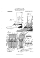
- Figure l is a side elevation of a foot equipped with our improvement, showing the same connected with the lower part of the leg.
- Fig. 2 is a central vertical section of the same.
- Fig. 3 is a section taken on the line 3&3, Fig. 2, the parts being shown on alarger scale.
- Fig. el is a section taken on the line 4 4, Fig. 3.
- Fig. 5 is a. detail view of the cylinder constituting a member of the ankle joint, shown on theJ same scale as in Figs. 3 and 4l.
- Fig. 6 is a detail view of the barrel member of the joint shown on the same scale.
- the numeral 5 designate the body of the foot, which is composed of wood.
- the toe member 6 is composed of felt, which possesses the necessary resilience, or yielding capacity, while walking.
- the toe member is connectedv with the body member by a bolt 7 whose head is countersunk in a recess S, the fastening nut applied to the opposite extremity of the bolt entering the recess 9 formed in the upper part of the foot just below the cushion 1() located forward of the ankle joint.
- a rubber cushion 12 In the rear of the joint is a rubber cushion 12 through which passes a spiral spring 13 incased by a flexible covering 14.
- the rear portion 15 of the body of the foot is V-shaped, its rear extremity tapering to a point. Below the part 15 is a rubber cushion 16.
- the particular feature to which we desire to call attention in this application is the ankle joint, which is located between the cushions l() and 12, and which includes a barrel member 17, a cylinder 18, and two bushings 19 and 20.
- the bushing 19 is set into a semicircular recess 2 formed transversely through the body 5 of the foot, and at the top thereof.
- the barrel 17 is applied to this bushing.
- the barrel has a centrally located V-shaped rib 21 circumferentially arranged and engagingacorresponding groove 22 formed in the bushing, the latter being preferably composed of mercury-tanned elk sole-leather.
- the latter is reinforced, as shown at j 24, forming shoulders 25 which also engage offsets 26 formed in the bushing to prevent endwise movement of the barrel.
- the barrel is formed hollow, and approximately half of its shell is cut away between the end members 27, leaving room for the cylinder which extends above the lower half of the shell, the cut away portion of the barrel leaving room for the introduction of the cylinder from above.
- the barrel is provided with elongated openings 28, while the cylinder is provided with openings 29 through which the arms 30 of a U-shaped bolt 31 pass, the said arms also passing through the elongated openings 28 of the barrel.
- Openings are also formed in the two bushing members 19 and 20, and so arranged with reference to the openings in the cylinder and barrel as to allow the arms 30 of the U-bclt to pass.
- the openings in the bushing 19 are of the same size, approximately, as the arms of the U-bolt, while the openings in the bushing 2O are elongated to correspond, or register,
- he arms 30 of the U-bolt pass downwardly through openings 34 formed in the body of the foot, the said openings leading to a recess 35 formed in the bottom of the foot member 5.
- the lower extremities of these arms 30 are threaded, as shown at 36, and nuts. 37 are applied thereto, a washer-plate 38 being interposed between the nuts and the bottom or upper wall of the recess.
- the nuts maintain the U-bolt securely in place within the body of the foot, so that the necessary movement of the U-bolt, cylinder, and the body of the foot, are permitted during the use o-f the foot while walking.
- the bushing 2O is provided with upper flanges 39 which the upper member 40 of the foot engage beyond the joint whereby this bushing is prevented from movement during the .movement of the cylinder and the U-bolt.
- the barrel is connected with the lower part of the leg member 41 by means of metal straps 42 and 43, whose lower extremities are perforated to receive the reduced ex tremities 44 and 45 of the barrel.
- metal straps 42 and 43 whose lower extremities are perforated to receive the reduced ex tremities 44 and 45 of the barrel.
- rIhe perforation in the strap 43 is circular to fit the part 44, which is of corresponding shape, while the reduced part 45 is polygonal in shape, preferably square, to fit an opening of corresponding shape formed in the strap 42, the said opening in the strap being arranged to maintain the upper edges 46 of the barrel in a horizontal plane while the strap occupies a position slightly rearwardly inclined from the vertical.
- the straps 42 and 43 are securely held in engagement with the barrel by means of screws 47 which are threaded into threaded openings 4S formed in the ends of the barrel. These screws are provided with ducts 49 for the introduction ica n of oil to the cavity in the barrel in which the cylinder is located, whereby the movement of the cylinder within the recess of the barrel may result in a minimum degree of friction.
Landscapes
- Health & Medical Sciences (AREA)
- Transplantation (AREA)
- Biomedical Technology (AREA)
- Cardiology (AREA)
- Oral & Maxillofacial Surgery (AREA)
- Engineering & Computer Science (AREA)
- Orthopedic Medicine & Surgery (AREA)
- Heart & Thoracic Surgery (AREA)
- Vascular Medicine (AREA)
- Life Sciences & Earth Sciences (AREA)
- Animal Behavior & Ethology (AREA)
- General Health & Medical Sciences (AREA)
- Public Health (AREA)
- Veterinary Medicine (AREA)
- Orthopedics, Nursing, And Contraception (AREA)
Description
A. E. GAINES & A. A. ERB.
ANKLE JOINT FOR ARTIFICIAL FEET.
APPLIGATION FILED AUG. zo, 191g.
1,069,409. Patented Aug. 5, 1913.
UNTTE STATES PATENT FFTQE,
ARTHUR E. GAINRs' AND ARTHUR A. ERB, or DENVER, COLORADO.
ANKLE-JOINT FoR ARTIFICIAL FEET.
Speccation of Letters Patent.
Patented Aug. 5,1913.
Application filed August 20, 1912. Serial No. 716,002.
T 0 all whom t may concern.'
Be it known that we, ARTHUR E. GAINES and ARTHUR A. ERB, citizens of the United States, residing in the city and county of Denver and State of Colorado, have invented certain new and useful Improvements in Ankle-Joints for Artificial Feet; and we do declare the following to be a full, clear, and exact description of the invention, such as will enable others skilled in the art to which it appertains to make and use the same, reference being had to the accompanying drawings, and to the letters and figures of reference marked thereon, which form a part o-f this specification.
Our invention relates generally to improvements in artificial feet, but more specifically to an ankle joint for use in connection with feet of this character.
The object of our present invention is to provide an ankle joint of sufficient strength for the purpose.
Tn articles of this class the joint is subjected to great strain, and unless the tensile strength of the fastening for the joint is considerable, this fastening will soon break, making it necessary to repair the foot.
Tn our improved construction, a barrel member is employed and fits into a recess transversely arranged in the body member of the foot between the front and rear cushions, the said barrel member engaging a bushing preferably composed of mercurytanned elk sole-leather, the barrel being prol vided with a circumferential rib and shoulders to prevent axial movement. This barrel is open at the top and between its extremities to receive a cylinder which constitutes the movable member of the joint, a raw-hide bushing being interposed between the cylinder and the barrel. The barrel is connected with the lower part of the limb by means of metal arms whose lower extremities are connected with the barrel and whose upper port-ion is secured to the lower part of the leg by suitable fastening devices. The joint is held in place from below by a U-bolt which passes through slots formed in the barrel and through openings in which the members of the U-bolt fit in the cylinder, the transverse upper extremity of the boltengaging a groove in the top of the cylinder. The members of this bolt are threaded and pass downwardly through openings formed in the body of the foot, their lower' extremities entering a recess cut in the bottom of the foot just forward of the heel in which a washer-plate is located, nuts being applied to the arms, or members, of the bolt, and countersunk in the said recess. The nuts are locked against turning by means of a raw-hide packing wedged into the recess between its opposite side walls and the nuts. This U-bolt is a very important feature and has been found, in actual practice, to give the necessary strength to the lower fastening member of the joint. By virtue of the bushings located between the cylinder and the barrel and between the latter and the body of the foot, t-he barrel is practically relieved from wear. Attention is called to the fact that the barrel, by virtue of its upper fastening, is held stationary within the foot, the only part of the joint which moves being the cylinder and the U-bolt, the
` members of the latter moving back and forth in the slots of the barrel.
The reason that great strength is required in the lower holding device for the joint, is that while walking, and during the time that the toe of the foot is pressed upon the ground or other surface, a relatively powerful leverage is produced, having a tendency to pull the joint upwardly out of the body, or lower portion of the foot. t is estimated that during the pressure of the toe of the foot where the latter is of ordinary length, upon the surface during walking, by a person weighing two hundred pounds, the lower fastening device or U-bolt of the joint is subjected to a strain of siX hundred pounds, while it is estimated that th'etensile strength of the U-bolt is six thousand pounds, or ten times the strength ordinarily required.
Having briefly outlined our improved construction, we will proceed to describe same in detail, reference being made to the accompanying drawing, in which is illustrated an embodiment thereof.
n this drawing: Figure l is a side elevation of a foot equipped with our improvement, showing the same connected with the lower part of the leg. Fig. 2 is a central vertical section of the same. Fig. 3 is a section taken on the line 3&3, Fig. 2, the parts being shown on alarger scale. Fig. el is a section taken on the line 4 4, Fig. 3. Fig. 5 is a. detail view of the cylinder constituting a member of the ankle joint, shown on theJ same scale as in Figs. 3 and 4l. Fig. 6 is a detail view of the barrel member of the joint shown on the same scale.
The same reference characters indicate the same parts in all the views.
Let the numeral 5 designate the body of the foot, which is composed of wood. The toe member 6 is composed of felt, which possesses the necessary resilience, or yielding capacity, while walking. The toe member is connectedv with the body member by a bolt 7 whose head is countersunk in a recess S, the fastening nut applied to the opposite extremity of the bolt entering the recess 9 formed in the upper part of the foot just below the cushion 1() located forward of the ankle joint. In the rear of the joint is a rubber cushion 12 through which passes a spiral spring 13 incased by a flexible covering 14. The rear portion 15 of the body of the foot is V-shaped, its rear extremity tapering to a point. Below the part 15 is a rubber cushion 16.
The features thus far described in detail, and given reference characters, are substantially the same as embodied in the construction of foot covered by Letters Patent of the United States, issued to us numbered 1008253, and dated November 7, 1911.
The particular feature to which we desire to call attention in this application is the ankle joint, which is located between the cushions l() and 12, and which includes a barrel member 17, a cylinder 18, and two bushings 19 and 20. The bushing 19 is set into a semicircular recess 2 formed transversely through the body 5 of the foot, and at the top thereof. The barrel 17 is applied to this bushing. The barrel has a centrally located V-shaped rib 21 circumferentially arranged and engagingacorresponding groove 22 formed in the bushing, the latter being preferably composed of mercury-tanned elk sole-leather. At the opposite ends of the barrel the latter is reinforced, as shown at j 24, forming shoulders 25 which also engage offsets 26 formed in the bushing to prevent endwise movement of the barrel. The barrel is formed hollow, and approximately half of its shell is cut away between the end members 27, leaving room for the cylinder which extends above the lower half of the shell, the cut away portion of the barrel leaving room for the introduction of the cylinder from above. The barrel is provided with elongated openings 28, while the cylinder is provided with openings 29 through which the arms 30 of a U-shaped bolt 31 pass, the said arms also passing through the elongated openings 28 of the barrel. Openings are also formed in the two bushing members 19 and 20, and so arranged with reference to the openings in the cylinder and barrel as to allow the arms 30 of the U-bclt to pass. The openings in the bushing 19 are of the same size, approximately, as the arms of the U-bolt, while the openings in the bushing 2O are elongated to correspond, or register,
with the openings 28 of the barrel, thus permitting the cylinder to move in the barrel and upon the bushing 2O without moving the latter.
The upper transverse member 32 of the U-bolt which connects the arms 30, occupies a position in a longitudinally disposed groove 33 formed in the cylinder. he arms 30 of the U-bolt pass downwardly through openings 34 formed in the body of the foot, the said openings leading to a recess 35 formed in the bottom of the foot member 5. The lower extremities of these arms 30 are threaded, as shown at 36, and nuts. 37 are applied thereto, a washer-plate 38 being interposed between the nuts and the bottom or upper wall of the recess. The nuts maintain the U-bolt securely in place within the body of the foot, so that the necessary movement of the U-bolt, cylinder, and the body of the foot, are permitted during the use o-f the foot while walking. The bushing 2O is provided with upper flanges 39 which the upper member 40 of the foot engage beyond the joint whereby this bushing is prevented from movement during the .movement of the cylinder and the U-bolt.
The barrel is connected with the lower part of the leg member 41 by means of metal straps 42 and 43, whose lower extremities are perforated to receive the reduced ex tremities 44 and 45 of the barrel. rIhe perforation in the strap 43 is circular to fit the part 44, which is of corresponding shape, while the reduced part 45 is polygonal in shape, preferably square, to fit an opening of corresponding shape formed in the strap 42, the said opening in the strap being arranged to maintain the upper edges 46 of the barrel in a horizontal plane while the strap occupies a position slightly rearwardly inclined from the vertical. rThis is necessary in order that the straps may be properly secured to the lower part of the artificial limb, since if the straps extended vertically from the barrel, a part of the strap would extend forward of the lower part of the limb, as will be apparent from an examination of Figs. 1 and 2 of the drawing. By virtue of the square, reduced part 45 on one end of the barrel, the latter is prevented from moving in the body of the foot after the strap 42 has been secured to the lower part of the limb, as illustrated. As the one strap connected as aforesaid is suflicient to maintain the barrel stationary, the perforation which receives the reduced portion 44 of the barrel, as well as the reduced part itself, is made circular in shape, as it simplifies the construction. lThe straps 42 and 43 are securely held in engagement with the barrel by means of screws 47 which are threaded into threaded openings 4S formed in the ends of the barrel. These screws are provided with ducts 49 for the introduction ica n of oil to the cavity in the barrel in which the cylinder is located, whereby the movement of the cylinder within the recess of the barrel may result in a minimum degree of friction.
Attention is called to the fact that the ends of the barrel do not extend to the outside of the foot on either side, whereby cavities 50 are left in which the extremities of the joint are countersunk, so to speak. Furthermore, the part of the foot above the joint, as well as the lower part of the artificial limb, is grooved, as shown at 5l and 52, to receive the metal straps 42 and 43. The upper extremities 54 of the metal straps are V-shaped to fit into grooves of corresponding shape formed in the limb, thus preventing the straps from moving down- Wardly in response to the strain upon the joint even if the fastening devices 53 were not employed.
In order to prevent the nuts 37 from turning after they have been applied to the threaded extremities of the members of the U-shaped bolt, we prefer to employ strips 55 of hard leather, which are driven into the spaces between the nuts and the side walls of the said recess o-r cavity.
From the foregoing description, the operation of our improved ankle joint will be readily understood. As the foot changes position with reference to the limb, the Uvbolt moves back and forth in the elongated openings 19 of the barrel, and the cylinder moves with the bolt, the bearing surface of the cylinder being the bushing 20. The bushing 19 also moves with the foot, while the barrel remains stationary, since it is secured to the leg by the metal straps 42 and 43. The bushing 20 also remains stationary with the barrel. The elongated openings 28 of the barrel are of suiiicient length to prevent the U-bolt members from engaging either extremity of these openings, thus preventing any wear on the parts which might result from such engagement.
Attention is called to the fact that the reinforcement of the barrel at its opposite ends whereby the shoulders 25 extend inwardly beyond the ends of the cylinder 18, gives great additional strength and wearing capacity to the barrel, since even if the barrel should be worn completely through between the rib 2l and the shoulders 25 the joint would still operate perfectly since the cylinder would be maintained in position by virtue of the fact that its extremities would bear upon the aforesaid reinforced portions of the barrel.
Having thus described our invention, what we claim is:
In an ankle joint for artificial limbs, the combination with the foot and leg members, of a barrel, a cylinder, the barrel being circular at both ends but open at the top to receive the cylinder, and a U-bolt, the cylinder and barrel having openings through which the arms of the bolt pass, the openings of the barrel being elongated, the cylinder being grooved longitudinally to receive the transverse member of the bolt, the barrel being secured to the leg member to prevent movement with the foot, substantially as described.
In testimony whereof we aifix our signatures in presence of two witnesses.
ARTHUR E. GAINES. ARTHUR A. ERB.
Witnesses:
OTTO E. HoDDIcK, MAY CLEMENTS.
Copies of this patent may be obtained for five cents each, by addressing the Commissioner of Patents, Washington, D. C.
Priority Applications (1)
| Application Number | Priority Date | Filing Date | Title |
|---|---|---|---|
| US71600212A US1069409A (en) | 1912-08-20 | 1912-08-20 | Ankle-joint for artificial feet. |
Applications Claiming Priority (1)
| Application Number | Priority Date | Filing Date | Title |
|---|---|---|---|
| US71600212A US1069409A (en) | 1912-08-20 | 1912-08-20 | Ankle-joint for artificial feet. |
Publications (1)
| Publication Number | Publication Date |
|---|---|
| US1069409A true US1069409A (en) | 1913-08-05 |
Family
ID=3137646
Family Applications (1)
| Application Number | Title | Priority Date | Filing Date |
|---|---|---|---|
| US71600212A Expired - Lifetime US1069409A (en) | 1912-08-20 | 1912-08-20 | Ankle-joint for artificial feet. |
Country Status (1)
| Country | Link |
|---|---|
| US (1) | US1069409A (en) |
Cited By (3)
| Publication number | Priority date | Publication date | Assignee | Title |
|---|---|---|---|---|
| US2617115A (en) * | 1949-07-25 | 1952-11-11 | Emmett C Ellery | Ankle joint for artificial legs |
| US5443522A (en) * | 1992-03-27 | 1995-08-22 | Otto Bock Orthopaedische Industrie Besitz und Verwaltungs-Kommanditgesell schaft | Artificial foot having a low-positioned joint and a horizontal plantar buffer |
| US5728175A (en) * | 1995-10-03 | 1998-03-17 | Rincoe; Richard G. | Artificial ankle joint with cushion structures and prosthetic devices formed therewith |
-
1912
- 1912-08-20 US US71600212A patent/US1069409A/en not_active Expired - Lifetime
Cited By (3)
| Publication number | Priority date | Publication date | Assignee | Title |
|---|---|---|---|---|
| US2617115A (en) * | 1949-07-25 | 1952-11-11 | Emmett C Ellery | Ankle joint for artificial legs |
| US5443522A (en) * | 1992-03-27 | 1995-08-22 | Otto Bock Orthopaedische Industrie Besitz und Verwaltungs-Kommanditgesell schaft | Artificial foot having a low-positioned joint and a horizontal plantar buffer |
| US5728175A (en) * | 1995-10-03 | 1998-03-17 | Rincoe; Richard G. | Artificial ankle joint with cushion structures and prosthetic devices formed therewith |
Similar Documents
| Publication | Publication Date | Title |
|---|---|---|
| US1001641A (en) | Ankle-joint. | |
| US375331A (en) | Julius beekey | |
| US497026A (en) | Artificial limb | |
| US204913A (en) | Improvement in furniture-pads | |
| US1539283A (en) | Shoe heel and sole lift | |
| US1069409A (en) | Ankle-joint for artificial feet. | |
| US1102343A (en) | Spring-heel. | |
| US1631710A (en) | Detachable heel | |
| US254816A (en) | g-reenwald | |
| US661593A (en) | Soft-tread horseshoe. | |
| US1139417A (en) | Shoe-heel. | |
| US2282952A (en) | Artificial leg | |
| US582961A (en) | George e | |
| US295623A (en) | Riding-saddle | |
| US1225455A (en) | Pneumatic shoe. | |
| US744801A (en) | Artificial limb. | |
| US759753A (en) | Artificial foot. | |
| US129340A (en) | Improvement in artificial legs | |
| US134088A (en) | Improvement in elastic boot and shoe heels | |
| US47281A (en) | Improvement in artificial legs | |
| US1246596A (en) | Shoe for dumping-cages. | |
| US854510A (en) | Artificial foot. | |
| US264812A (en) | Artificial leg | |
| US585582A (en) | Shoe-spring | |
| US1318651A (en) | Shoe-stretcher |