US1069376A - Cooking apparatus. - Google Patents
Cooking apparatus. Download PDFInfo
- Publication number
- US1069376A US1069376A US65903911A US1911659039A US1069376A US 1069376 A US1069376 A US 1069376A US 65903911 A US65903911 A US 65903911A US 1911659039 A US1911659039 A US 1911659039A US 1069376 A US1069376 A US 1069376A
- Authority
- US
- United States
- Prior art keywords
- air
- duct
- heat
- oven
- mass
- Prior art date
- Legal status (The legal status is an assumption and is not a legal conclusion. Google has not performed a legal analysis and makes no representation as to the accuracy of the status listed.)
- Expired - Lifetime
Links
- 238000010411 cooking Methods 0.000 title description 13
- 238000010438 heat treatment Methods 0.000 description 31
- 238000005338 heat storage Methods 0.000 description 12
- 239000000463 material Substances 0.000 description 8
- 230000001737 promoting effect Effects 0.000 description 7
- 239000004020 conductor Substances 0.000 description 6
- 230000001105 regulatory effect Effects 0.000 description 5
- 239000011810 insulating material Substances 0.000 description 4
- XLYOFNOQVPJJNP-UHFFFAOYSA-N water Substances O XLYOFNOQVPJJNP-UHFFFAOYSA-N 0.000 description 2
- 108091023288 HOTAIR Proteins 0.000 description 1
- 238000010276 construction Methods 0.000 description 1
- 230000001276 controlling effect Effects 0.000 description 1
- 238000001816 cooling Methods 0.000 description 1
- 238000005485 electric heating Methods 0.000 description 1
- 230000005611 electricity Effects 0.000 description 1
- 239000002184 metal Substances 0.000 description 1
- 229940061319 ovide Drugs 0.000 description 1
- 229920000136 polysorbate Polymers 0.000 description 1
- 235000002020 sage Nutrition 0.000 description 1
- 239000007787 solid Substances 0.000 description 1
Images


Classifications
-
- F—MECHANICAL ENGINEERING; LIGHTING; HEATING; WEAPONS; BLASTING
- F24—HEATING; RANGES; VENTILATING
- F24C—DOMESTIC STOVES OR RANGES ; DETAILS OF DOMESTIC STOVES OR RANGES, OF GENERAL APPLICATION
- F24C15/00—Details
- F24C15/34—Elements and arrangements for heat storage or insulation
Definitions
- WITNESSES INVENTOR ATTORNEYS UNITED STATES PATENT orricn GEORGE:GILBERT'BELL, OF KEN SIN GTON, LONDON, ENGLAND, ASSIGNOR 7 HEAT STORAGE COMPANY, ACORIEORATION OF NEW.YORK.
- This invention relates to improvements in apparatus-for heating'air or other media by means of electricity, in which the electrical energy is transformed into'and-is stored in the form of heat to be used as required, preferably by using a heat accumulator or a mass of material-having a high'specific heatfva'lue and a high thermal conductivity such as
- Now-the present invention has for its ob ject to-pr-ovide meansefor promoting or increasing the circulation" of the medium in such an electrical coo-king apparatus.
- the oven is arranged above the heat ,zag'paths for the air or the duct may be provide .short time if necessary.
- auxiliary means for causing a circulation such as an auxiliaryheater, is inserted in the flow pipe or conduit.
- an additional heater may be arranged in the oven near the top to' top heat or to heat quicklyfor a
- the air duct may be provided with bafli-e plates to provide zi co-iled or otherwise arranged so as to deflect the air and cause it to impinge against the heated sides of the duct, such deflections serving to more thoroughly heat the air and dampers or valves may be provided for regrangement of heating apparatus.
- the beat accumulator or mass at is in the form'of a parallelepiped and has a coiled air duct b cast therein.
- the air duct 12 emerges at one end at the middle of the top of the heat accumulator a into the hot air supply pipe 0 which passes 'up into the oven arranged'immediateiy "above the'heat accumulator a.
- the return pipefe fonthe cooled air is led into the other heat accumulator a so that the air is reheated in the duct 5.
- the heat accumulator a and oven d areeach'inelosed in a casing f of a heat insulating material which in turn is conveniently incased in acasing g of sheet metal or other suitable material.
- accumulator is fitted with a. heater in of known type'a-rranged in a recess in portion of the mass.
- anenlargement 2' is suitably made, in the hotair supply pipe 0, at or near the point at which it leaves the heat accumulator a, to contain an additional heater 7' which tends to set up additional convection currents in theair.
- the distribution of heat ifis. eflicientlycontrolled by dampers or valves A1 and l of any known type and arranged'one at the outlet and the'other at the inlet of the air duct 12. 7
- the heat'accum'ulator a is also in the form-of, a parallelepiped and is provided with a heating element 71-.
- the said heat accumu' lator has a horizontal and preferably cylindrical-ail; duct provided with' vertical plates m serving "as bathe-plates and suitably cast into the thermal mass or otherwise mounted in the duct 1) at intervals along its length,
- the said plates preferably have central apertures through which is passed the central shaft or core. 12 and holes 0 are punched or drilled in the plates m, the holes in succeeding plates being out of alinement, so that thuszig-zag or tortuous paths are provided for the air.
- The'hot-air supply pipe or duct 0 emerges at or near the inner end of the air duct 6 at the lower part of the s
- the heat the lower A end ofthe air duct 6 in the heataccumulator a and may pass directly up intothe oven (Z which, as before, 18 arranged immediately above the heat accumulator.
- the oven and heat accumulator are also incased in insulating material f.
- the return passage 6 for the cooled air, which passage is formed be tween the outersoveu door 7) and the inner oven door (7 connnunicatcs. ⁇ vith the oven by holes 1' in the oven door (7, and leads into-the conduit 8 which opens into the front of the air duct 6.
- the additional heater 7' is in this construction arranged-in the hot'air supply pipe or duct 0 itself.
- the distribution of heat is controlled by hit and miss valves t and it operated through handles u and these can be so operated as to completely isolate the heat accumulator a, and by a simple sliding damper 'v, and if desired a sliding damper orhit-and-miss valve w may be provided for further regulating the flow of air through the holes r.
- holes m with a damper or hit-and-miss valve 3 maybe provided at the lower end of the oven door 9.
- a duct or uptake a may be provided leading from, or forming a con-v tinuation of, the hot air supply duct 0 and this uptake is providedwith dampers or valves 1 which can be so operated as to'permit the hot air to be delivered to any desired part of the oven d. For instance, if most heat is required at the lower part of the oven, the lowermost damper or valve 1 is opened as shown, and'if most heat is required at the top or at an intermediate part of the oven, the uppermost damper of valve Z or an intermediate damper or valve l, respectively, is opened, the other dampers being then closed.
- This uptake 2 is ofcourse not an essential part of the invention and may be dispensed with if desired, in which case the duct 0 would communicate direct with the oven 03. 1
- the cooking or heating apparatus accord ing to this invention may, if desired, be provided with yet another and auxiliary electric heater 2 placed, as shown in Figs. 1,
- the heaters j and 2 may be adapted to be switched on when required by means of switches 3 and 4 re-' spectively and the main heater his switched on or off by a switch 5 according to the load on the central station or to equalize the demand of the cooking apparatus. Further the apparatus may, as shown in Figs. 3. and 4, be inelosed in a tank 6 for water which may be heated by any heat escaping through the heat insulating material What I claim as new and desire to secure by Letters Patent, is:
- an air heater provided with a heat storage mass having a solid core and a series of projecting anrihlar flanges or ringsprovided with holes arranged in staggered fashion, whereby the air will be retarded in its passage through the air heater and will be brought frequently into contact with the heated surface of the heat storage mass and its projecting rings.
- Apparatus for heating air or other me-. dia for cooking or other purposes comprissisting of a mass of a material capable of storing heat and belnga good conductor of heat, electrical means for heating said mass,
- duct in said mass through which the air or other medium to be heated is adapted to pass, baffles in said duct so adapted as to proing in combination, a heat accumulator convide a zig-zag or tortuous path for. the air or other medium through said duct, a chamber serving as an oven and connected by passages with both ends of said duct, and means for promoting circulation of the air orother medium through said duct and said chamber, substantially as set forth.
- Apparatus for heating air or other media for cooking or other purposes comprising in combination, a heat accumulator consisting of'a mass of a material capable of storing heat and being a good conductor of.
- a duct in said mass through which the air or other inedium to be heated is adapted to pass, a chamber connected with both ends of said duct, and means for promoting circulation of the air or other medium through said duct and said chamber, substantially as set forth.
- a chamber serving as an oven arranged above said mass a passage connecting one end of said duct withsaid chamber, a'pas-' sage connecting the other end of said duct with saidchamber, an auxiliary' electric heating means in said chamber and auxiliary means in one of said passages'for promoting circulationof 'the air or other medium through salid duct and said chamber, substantially as set forth,
- Apparatus for heating air or other media for cooking or other purposes comprising in combination, a heat accumulator consisting of a mass of a material capable of storing heat and being a good conductor of heat, electrical means for heatingesaid mass a duct in said mass through which the air or other medium to be heated is adapted to pass,'a chamber serving as an oven ar ranged above said mass, a passage connecting one end of said duct with said chamber, a passage connecting the other end of said duct with said chamber, auxiliary means in one of said passages for promoting circulation of the air or other medium through said duct and said chamber, and means in the said passages for regulating the circulation of the air or other'medium,--substantially as set forth.-
- Apparatus for heating air or other media for cooking or other purposes comprising in combination, a heat acumulator consi'sting of a mass of a material capableof storing heat and beinga good conductor of heat,
- baflles in said duct so adapted as to provide a zig zag or tortuous path for'the air or other medium through said duct a chamben serving as an oven and arranged above said mass, an uptake in sai'd chamber communicating with one end ofsaid duet, means for controlling the supply of hot air or other medium from said uptake into "id chamber, an inner door of said chamber; an outer door of said chamber, a passagebetween said doors, holes in said inner door to allow the air orother medium to pass from said chamber into said passage between said doors, means for regulating the flow of air or otherJnedium through said holes, a conduit connecting the passage between said two doors with the otherjend of the said duct, electrical heating means;
Landscapes
- Engineering & Computer Science (AREA)
- Chemical & Material Sciences (AREA)
- Combustion & Propulsion (AREA)
- Mechanical Engineering (AREA)
- General Engineering & Computer Science (AREA)
- Electric Stoves And Ranges (AREA)
Description
G. BELL. COOKING APPARATUS. APPLICATION FILED HOV. 7,1911.
Patented Aug. 5, 1913.
3 SHEETS-SHEET 1.
INVENTOR WITNESSES:
WW ATTORNEYS G. G. BELL. COOKING APPARATUS. APPLIUA'I'ION 1111311 11017.7, 1911.
Patented Aug. 5, 1913.
3 SHEETS-SHEET 2.
mvmmn WW/ML BY 7L 2 $15k WITNESSES:
G. G. BELL. COOKING APPARATUS. APPLICATION FILED NOV. 7, 1911.
1,069,376, Patented Aug. 5, 1913.
s sums-sum a.
WITNESSES: INVENTOR ATTORNEYS UNITED STATES PATENT orricn GEORGE:GILBERT'BELL, OF KEN SIN GTON, LONDON, ENGLAND, ASSIGNOR 7 HEAT STORAGE COMPANY, ACORIEORATION OF NEW.YORK.
r ELECTRIC CQOKING APPARATUS.
Specification of Letters Patent.
Patented Aug. 5, 1913.
To all whom it may concern:
Be it knownt'hat I, GEORGE GILBERT BELL, a subject of the King of Great Britain, and a resident o'fKensington, London, England, have invented ,certain --new and useful Improvements in Cooking Apparatus, of which the following is aspecification.
This invention relates to improvements in apparatus-for heating'air or other media by means of electricity, in which the electrical energy is transformed into'and-is stored in the form of heat to be used as required, preferably by using a heat accumulator or a mass of material-having a high'specific heatfva'lue and a high thermal conductivity such as Now-the present invention has for its ob ject to-pr-ovide meansefor promoting or increasing the circulation" of the medium in such an electrical coo-king apparatus. To
' this end the oven is arranged above the heat ,zag'paths for the air or the duct may be provide .short time if necessary.
accumulator and is connected thereto by two pipes or ducts, one for the flow and the other for the return of the medium and in order to further increase the circulation of the heated air or other medium, auxiliary means for causing a circulation such as an auxiliaryheater, is inserted in the flow pipe or conduit. Moreover an additional heater may be arranged in the oven near the top to' top heat or to heat quicklyfor a The air duct may be provided with bafli-e plates to provide zi co-iled or otherwise arranged so as to deflect the air and cause it to impinge against the heated sides of the duct, such deflections serving to more thoroughly heat the air and dampers or valves may be provided for regrangement of heating apparatus.
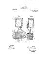
According to the arrangement illustrated in Figs 1 and 2, the beat accumulator or mass at is in the form'of a parallelepiped and has a coiled air duct b cast therein. The air duct 12 emerges at one end at the middle of the top of the heat accumulator a into the hot air supply pipe 0 which passes 'up into the oven arranged'immediateiy "above the'heat accumulator a. The return pipefe fonthe cooled air is led into the other heat accumulator a so that the air is reheated in the duct 5. The heat accumulator a and oven d areeach'inelosed in a casing f of a heat insulating material which in turn is conveniently incased in acasing g of sheet metal or other suitable material. accumulator is fitted with a. heater in of known type'a-rranged in a recess in portion of the mass. In order'to still further improve the circulation of the medium, anenlargement 2' is suitably made, in the hotair supply pipe 0, at or near the point at which it leaves the heat accumulator a, to contain an additional heater 7' which tends to set up additional convection currents in theair. The distribution of heat ifis. eflicientlycontrolled by dampers or valves A1 and l of any known type and arranged'one at the outlet and the'other at the inlet of the air duct 12. 7
According to a modified and convenient arrangement as illustrated in Figs. 3 and 4:, the heat'accum'ulator a is also in the form-of, a parallelepiped and is provided with a heating element 71-. The said heat accumu' lator has a horizontal and preferably cylindrical-ail; duct provided with' vertical plates m serving "as bathe-plates and suitably cast into the thermal mass or otherwise mounted in the duct 1) at intervals along its length, The said plates preferably have central apertures through which is passed the central shaft or core. 12 and holes 0 are punched or drilled in the plates m, the holes in succeeding plates being out of alinement, so that thuszig-zag or tortuous paths are provided for the air. The'hot-air supply pipe or duct 0 emerges at or near the inner end of the air duct 6 at the lower part of the s The heat the lower A end ofthe air duct 6 in the heataccumulator a and may pass directly up intothe oven (Z which, as before, 18 arranged immediately above the heat accumulator. The oven and heat accumulator are also incased in insulating material f. The return passage 6 for the cooled air, which passage is formed be tween the outersoveu door 7) and the inner oven door (7 connnunicatcs.\vith the oven by holes 1' in the oven door (7, and leads into-the conduit 8 which opens into the front of the air duct 6. The additional heater 7' is in this construction arranged-in the hot'air supply pipe or duct 0 itself. The distribution of heat is controlled by hit and miss valves t and it operated through handles u and these can be so operated as to completely isolate the heat accumulator a, and by a simple sliding damper 'v, and if desired a sliding damper orhit-and-miss valve w may be provided for further regulating the flow of air through the holes r. Moreover holes m with a damper or hit-and-miss valve 3 maybe provided at the lower end of the oven door 9. v
- In order to further control the distribution of the heat a duct or uptake a maybe provided leading from, or forming a con-v tinuation of, the hot air supply duct 0 and this uptake is providedwith dampers or valves 1 which can be so operated as to'permit the hot air to be delivered to any desired part of the oven d. For instance, if most heat is required at the lower part of the oven, the lowermost damper or valve 1 is opened as shown, and'if most heat is required at the top or at an intermediate part of the oven, the uppermost damper of valve Z or an intermediate damper or valve l, respectively, is opened, the other dampers being then closed. This uptake 2 is ofcourse not an essential part of the invention and may be dispensed with if desired, in which case the duct 0 would communicate direct with the oven 03. 1
The cooking or heating apparatus accord ing to this invention may, if desired, be provided with yet another and auxiliary electric heater 2 placed, as shown in Figs. 1,
'2, 3 and 4, in the oven at near the top to provide top heat or to-heat quickly for a short time if necessary. The heaters j and 2 may be adapted to be switched on when required by means of switches 3 and 4 re-' spectively and the main heater his switched on or off by a switch 5 according to the load on the central station or to equalize the demand of the cooking apparatus. Further the apparatus may, as shown in Figs. 3. and 4, be inelosed in a tank 6 for water which may be heated by any heat escaping through the heat insulating material What I claim as new and desire to secure by Letters Patent, is:
1. The combination of an oven, an air heater for supplying heated air thereto provided with a heat storage mass having a passageway for the air therethrough de'flected.
at numerous places, whereby the air will be retarded in its passage through the air heater and will be brought frequently into contact with the heated surfaces of the heat storage mass.
2. The combination of an air heater provided with a heat storage mass'having a passagewayfor the air therethrough deflected at numerous places, whereby the air will be retarded in its passage through the airheater and will be brought frequently into contact with the heated surfaces of the heat storage mass.
3. The combination of air heater proafded with a heat storage mass having a series of projecting annular rings provided with holes arranged in the difierent rings in staggered fashion, whereby the air will be retarded in its passage thrpugh the air heater and will be brought frequently into contact with the heated surfaces of the heat storage mass, an oven supplied with heated air from the air heater, and an electrical heating element for heating the heat storage mass.
4. In a cooking device an air heater provided with a heat storage mass having a solid core and a series of projecting anrihlar flanges or ringsprovided with holes arranged in staggered fashion, whereby the air will be retarded in its passage through the air heater and will be brought frequently into contact with the heated surface of the heat storage mass and its projecting rings.
5, Apparatus for heating air or other me-. dia for cooking or other purposes, comprissisting of a mass of a material capable of storing heat and belnga good conductor of heat, electrical means for heating said mass,
.a duct in said mass through which the air or other medium to be heated is adapted to pass, baffles in said duct so adapted as to proing in combination, a heat accumulator convide a zig-zag or tortuous path for. the air or other medium through said duct, a chamber serving as an oven and connected by passages with both ends of said duct, and means for promoting circulation of the air orother medium through said duct and said chamber, substantially as set forth.
.6. Apparatus for heating air or other media for cooking or other purposes, comprising in combination, a heat accumulator consisting of'a mass of a material capable of storing heat and being a good conductor of.
heat, electrical means for heating said mass,-
a duct in said mass through which the air or other inedium to be heated is adapted to pass, a chamber connected with both ends of said duct, and means for promoting circulation of the air or other medium through said duct and said chamber, substantially as set forth.
7; Apparatus for heating air or other media for cooking or other pur-poses,{ cpmpr"ising in combination, a heat accumulator .consisting of a mass of a material capable of storing heat and being a good conductor of heat, electrical means for heating said mass, a duct insaid mass through which the air or other medium to be heated is adapted to pass, a chamber connected with both ends of said duct, and electrical means for promoting circulation of the air or other medium through said duct and said chamber, substantially as set forth.
' other medium to be heated. is adapted to pass, a chamber serving as an oven arranged above said mass, a passage connecting one end of said duct withsaid chamber, a'pas-' sage connecting the other end of said duct with saidchamber, an auxiliary' electric heating means in said chamber and auxiliary means in one of said passages'for promoting circulationof 'the air or other medium through salid duct and said chamber, substantially as set forth,
9. The combination of an oven, an air heater, arranged below the oven, an electrical heating element for the air heater, a vent;- cal air flue leading fromthe air heater to the oven, an electrical heating element ar ranged in the flue, and means for cutting the electrical heating element for the air heater out of operation and the electrical heating element in the vertical flue into operation for'heating the air therein and for starting and maintaining an upward flow of heated air therein.
10. The combination of an oven, an air heater provided with a heat storage mass arranged below the oven,-an electrical heating element for the said heat storage mass, a vertical air flue leading from the air heater to the oven, an electrical heating elementarranged in the flue for heating the air therein and for starting and maintaining an upward flow of heated air therein, means for cutting one of the heating elemntsinto operation and the other out of operation, and a return passage from the oven to the air heater for" the return to it of the spentheated air.
11. Apparatus for heating air or other media for cooking or other purposes, comprising in combination, a heat accumulator consisting of a mass of a material capable of storing heat and being a good conductor of heat, electrical means for heatingesaid mass a duct in said mass through which the air or other medium to be heated is adapted to pass,'a chamber serving as an oven ar ranged above said mass, a passage connecting one end of said duct with said chamber, a passage connecting the other end of said duct with said chamber, auxiliary means in one of said passages for promoting circulation of the air or other medium through said duct and said chamber, and means in the said passages for regulating the circulation of the air or other'medium,--substantially as set forth.-
12. The combination of an oven, an air heater arranged 'below the oven, an electrical heating element for the air. heater, a -YrtlCll air flue leading from the air heater to the men, an QlQCtllCill' heating element arranged in the flue for heating the air therein and for starting and maintaining anupward fiow of heated air therein, and a return passage from the oven to the air heater for the return to it of the spentheated air.
13. Apparatus for heating air or other media for cooking or other purposes,-co1nprising in combination, a heat accumulator consisting of a mass of a material capable of storing heat and being a good conductor of heat, electrical means for heating said mass, a duct in said mass through which the air orother medium to be heated is adapted to pass, a chamber serving as an oven and connected with one end. of said duct, an uptake in said chamber communicatin with the other end of said duct and adapte to be placed in communication with said chamber, means for regulating the supply of hot air or other medium from said uptake into-said chamber, and means for circulating the airor other medium through said duct and,
said chamber, substantially as set forth 14. Apparatus for heating air or other media for cooking or other purposes,comprising in combination, a heat acumulator consi'sting of a mass of a material capableof storing heat and beinga good conductor of heat,
electrical means for heating said mass, a
'duct in said mass through whichthe air or other medium to be heated is adapted to pass, baflles in said duct so adapted as to provide a zig zag or tortuous path for'the air or other medium through said duct a chamben serving as an oven and arranged above said mass, an uptake in sai'd chamber communicating with one end ofsaid duet, means for controlling the supply of hot air or other medium from said uptake into "id chamber, an inner door of said chamber; an outer door of said chamber, a passagebetween said doors, holes in said inner door to allow the air orother medium to pass from said chamber into said passage between said doors, means for regulating the flow of air or otherJnedium through said holes, a conduit connecting the passage between said two doors with the otherjend of the said duct, electrical heating means;
in the first-named passage for promoting I circulation of the air or other medium through saidduct and said chamber, means, I in the said passages for regulating the circulation of the air or other "medium, an auxiliary heating means in said chamber, a coveringof heat insulating material surrounding said mass and said ehamber and a water jacket surrounding said covering. of insulating "material, forth.
15. The combination of an 'oven, an air substantially as set heatei for-supplying heated air thereto, a door for the oven, an inclosed space outside -'of the oven door, one or more openings in the oven door for the escape of heated air '5 from the oven into such inclosed space,- a i door in the wall of such inclosed space 0pposite the oven door, and a return passage from the inclosed space to the air heater, whereby the spent heated. air may be used 10 to prevent undue cooling of the oven, esper cially when access is being hd .to the oren, and may be reheated and used over again.
In testimony whereof, I have signed my name to this specification, in the presence of O. J. WORTH,
H. D..JAMESQN.
Priority Applications (1)
| Application Number | Priority Date | Filing Date | Title |
|---|---|---|---|
| US65903911A US1069376A (en) | 1911-11-07 | 1911-11-07 | Cooking apparatus. |
Applications Claiming Priority (1)
| Application Number | Priority Date | Filing Date | Title |
|---|---|---|---|
| US65903911A US1069376A (en) | 1911-11-07 | 1911-11-07 | Cooking apparatus. |
Publications (1)
| Publication Number | Publication Date |
|---|---|
| US1069376A true US1069376A (en) | 1913-08-05 |
Family
ID=3137613
Family Applications (1)
| Application Number | Title | Priority Date | Filing Date |
|---|---|---|---|
| US65903911A Expired - Lifetime US1069376A (en) | 1911-11-07 | 1911-11-07 | Cooking apparatus. |
Country Status (1)
| Country | Link |
|---|---|
| US (1) | US1069376A (en) |
Cited By (4)
| Publication number | Priority date | Publication date | Assignee | Title |
|---|---|---|---|---|
| US2561517A (en) * | 1946-12-26 | 1951-07-24 | Ladge Morris | Dispensing cabinet |
| US2904666A (en) * | 1957-11-08 | 1959-09-15 | Jackson Robert Alfre Frederick | Electric space heaters |
| US3012332A (en) * | 1959-04-16 | 1961-12-12 | Gen Electric | Heat storage reservoir for clothes dryer |
| US12130086B1 (en) * | 2024-04-01 | 2024-10-29 | Alterno Pte. Ltd. | Thermal storage batteries and thermal storage battery systems for drying agricultural and food products |
-
1911
- 1911-11-07 US US65903911A patent/US1069376A/en not_active Expired - Lifetime
Cited By (4)
| Publication number | Priority date | Publication date | Assignee | Title |
|---|---|---|---|---|
| US2561517A (en) * | 1946-12-26 | 1951-07-24 | Ladge Morris | Dispensing cabinet |
| US2904666A (en) * | 1957-11-08 | 1959-09-15 | Jackson Robert Alfre Frederick | Electric space heaters |
| US3012332A (en) * | 1959-04-16 | 1961-12-12 | Gen Electric | Heat storage reservoir for clothes dryer |
| US12130086B1 (en) * | 2024-04-01 | 2024-10-29 | Alterno Pte. Ltd. | Thermal storage batteries and thermal storage battery systems for drying agricultural and food products |
Similar Documents
| Publication | Publication Date | Title |
|---|---|---|
| US1069376A (en) | Cooking apparatus. | |
| US1719659A (en) | Heating and ventilating apparatus | |
| US1517434A (en) | Heater | |
| US3396781A (en) | Process and apparatus for the recovery of waste heat | |
| US1907357A (en) | Electric hot air furnace | |
| US1998329A (en) | Elastic fluid generator or boiler | |
| US2417606A (en) | Furnace for the production of carbon black | |
| US1758474A (en) | Storage and utilization of electrically-generated heat | |
| US2369993A (en) | Fluid heater | |
| US1349130A (en) | Heating apparatus | |
| US1869623A (en) | Electric heating apparatus | |
| US558714A (en) | Electric heating | |
| US1770936A (en) | Recuperator | |
| US3786232A (en) | Apparatus for the charging and discharging of storage heaters | |
| US1693133A (en) | Electric heater | |
| US1819608A (en) | Heating apparatus | |
| US975107A (en) | Electric baking-oven. | |
| US2600044A (en) | Domestic electric furnace | |
| US1430596A (en) | Heating apparatus | |
| US1462339A (en) | Air heater | |
| US2254383A (en) | Heat exchanger | |
| US762591A (en) | Device for heating or cooling air. | |
| US1052834A (en) | Air-heater. | |
| US1868824A (en) | Oven-circulating air type | |
| US652867A (en) | Electrical drying apparatus. |