US1069360A - Feed-water heater. - Google Patents
Feed-water heater. Download PDFInfo
- Publication number
- US1069360A US1069360A US63178311A US1911631783A US1069360A US 1069360 A US1069360 A US 1069360A US 63178311 A US63178311 A US 63178311A US 1911631783 A US1911631783 A US 1911631783A US 1069360 A US1069360 A US 1069360A
- Authority
- US
- United States
- Prior art keywords
- water
- heating chamber
- chamber
- heater
- tank
- Prior art date
- Legal status (The legal status is an assumption and is not a legal conclusion. Google has not performed a legal analysis and makes no representation as to the accuracy of the status listed.)
- Expired - Lifetime
Links
- XLYOFNOQVPJJNP-UHFFFAOYSA-N water Substances O XLYOFNOQVPJJNP-UHFFFAOYSA-N 0.000 title description 49
- 238000010438 heat treatment Methods 0.000 description 32
- 230000003137 locomotive effect Effects 0.000 description 4
- 238000010276 construction Methods 0.000 description 3
- 102000004405 Collectins Human genes 0.000 description 1
- 108090000909 Collectins Proteins 0.000 description 1
- 235000014443 Pyrus communis Nutrition 0.000 description 1
- 238000007689 inspection Methods 0.000 description 1
- 230000001105 regulatory effect Effects 0.000 description 1
Images


Classifications
-
- F—MECHANICAL ENGINEERING; LIGHTING; HEATING; WEAPONS; BLASTING
- F22—STEAM GENERATION
- F22D—PREHEATING, OR ACCUMULATING PREHEATED, FEED-WATER FOR STEAM GENERATION; FEED-WATER SUPPLY FOR STEAM GENERATION; CONTROLLING WATER LEVEL FOR STEAM GENERATION; AUXILIARY DEVICES FOR PROMOTING WATER CIRCULATION WITHIN STEAM BOILERS
- F22D1/00—Feed-water heaters, i.e. economisers or like preheaters
- F22D1/42—Feed-water heaters, i.e. economisers or like preheaters specially adapted for locomotives
Definitions
- the invention relates to feed water heaters and particularly to feed water heaters for locomotives.
- One of the objects of my invention is the, provision of improved means for quickly and economically heating a small portion of water in the tender-tank by passing. the water through tubes in a heating chamber whereby the area of heating surface is greatly increased.
- Another of the objects of my invention is the provision of an improved means for preventing circulationbetween the heated and the cool portions of the water in the heater and tank.
- Another object is the provision of a feed water heater of the character specified having improved means for collecting the con'-.
- my invention is designed to provide an improved arrangement of tender and feed water heater which is simple in construction and effective in operation.
- FIG. 1 is a diagrammatic illustration of a locomotive and-tender. havingimy improved heater applied; ' Figure 2 is a partial longitudinal section through the tender; Figure 3 is a, transverse section on the line IIIIII of Figure 2'on an enlarged scale; and Figures 4 and v5are detail'views of the thermostat and valve mechanism employedin my improved heater.
- the chamber, 12, has communication at the top with the main tank, 10, by means of a portor opening 14.
- a ser-ies of tubes, 15, eX- tend through the heating chamber and open into the water chambers.
- Steam is admitted to the heating chamber from the pipe 7 through the valve 16 and the pipe 17, said valve being controlled by a thermostat, 18, the operation of which will hereinafter ap- ,pear.
- the water chamber, 13, ' is provided with a connection 19 for the usual steam mjector, not shown, and with a vent pipe, 20, extending to a point substantially at the normal level of the water in the main tank, and adapted to exhaust the heater fromsair and permit water to flow therein when filling the tender tank.
- Ii'he end plates 12 and 13 of the heating chamber are preferably made detachable in order to give free access to the tubes 1;.5.'
- the waterchamber', 12, is divided into twocompartments by means of the wall, 23, the said compartments having communication with each other at a point substantially belowthe level of the tubes'15. (See Figure 2).
- thermostatic valve control for the admis- .sion ofsteam.
- the steam admission valve, 16 is normally held in closed position b means of airpressure admitted to the va ve casing from the main reservoir or other source of supply, by means of the pipe 24 and the port 25, which port is'controlled by the thermostat, 18.
- the thermostat is mounted in the water chamber, 13. and is provided with a stem, 26, which seats on the port 25 when inclosed position.
- the stem 26 is normally held in closed position by means of the spring, 29, until the water in the heater reaches the predetermined deate-ant gree, which time vthe action of the heat expands the thermostat proper, 30, and raises the stem 26 from off its seat and thereby permits air pressure to ehter the casing and close the steam valve.
- the thermostat will contract and the spring 29 will seat the stem 26 and close the port 25, thereby permitting the steam valve to open.
- the condensate in the heating chamber will collectin the receptacle 21' and upon theadmission of steam into the heating chamber, such condensate will be blown up through the pipe 22 and discharged into the top of the tender tank.
- the pipe 22 is provided with a looped portion 22, which retains a small amount of condensate after exhaust steam has been admit-ted to the heateruand the steam valve has been closed.
- the condensate that will collect in this loop portion is sufiicient to prevent the steam from escaping from the heating chamber during the periods when the steam valve is closed.
- a main tank an elongated heating chambermounted therein at a point below the level of the water line, said chamber having no communication with the tank, a water chamber adjacent the forward end of the heating chamber, a water chamber adjacent the rearward end of the heating chamber opening into the main tanlr, and a series of tubes ea tending through the heatin chamber and opening into the water chambers, the said rear water chamber being composed of two communicating compartments opening into each other at their lower portions.
- a feed water heater for locomotive ten ders comprising a heating chamber located in the bottom. of the tender tank, a water chamber at the forward end of the heating chamber, a water chamber at the rearward end thereof communicating with the main tender tank, a pluralit of tubes extending through the heating c amber and opening into the water chambers, an outlet from the forward water chamber, a wall dividing the rear water chamber into two compartments communicating with each other at a point below the level of the tubes, and means tor admitting steam to the heating chamber.
- a main tank a heating chamber therein, a water chamber at each end of said heating chamber, one ot which communicates with the main tank, a series of tubes extending through the heating chamber and opening into the water chambers, a removable plate for one of the water chambers opposite the ends of the tubes arranged to give access to the tubes when the plate is removed, a steam inlet to the heating chamber, and a discharge outlet :trom one of the water chambers.
- a main tank a heating chamber therein, a water chamber at each end oi said heating chamber, one of which commimicates with the main tank, a series of tubes extending through the heating chamber and opening into the water chambers, a removable plate for each of the water chambers opposite the ends of the tubes in such chambers, and arranged to give access to the end of the tubes when the plates'are removed, a steam inlet to the heating chamber, and a disgharge outlettrom one of the water chamere.
Landscapes
- Engineering & Computer Science (AREA)
- Physics & Mathematics (AREA)
- Thermal Sciences (AREA)
- Mechanical Engineering (AREA)
- General Engineering & Computer Science (AREA)
- Devices For Medical Bathing And Washing (AREA)
Description
H. H. VAUGHAN; FEED WATER HEATER. APPLICATION FILED 111111: 7, 1911.
1 9 3 Patented Aug. 5, 1913.
4 SHEETS-SHEET 1.
WITNESS24 INpV/ENTZ/R H. H. VAUGHAN. FEED WATER HEATER. APPLICATION FILED JUNE 7, 1911.
1,069,860, Patented Aug. 5, 1913' 4 SHEETSSHEET 2.
H. H. VAUGHAN. FEED WATER HEATER.
APPLICATION FILED JUNE 7, 1911.
1,069,36Q Patented Aug.5,1913.
4 SHEETS-SHEET 3.
WITNESj ES INVENTOR .7
H. H. VAUGHAN.
FEED WATER HEATER.
' APPLICATION FILED J U'NI17,'1911. 1,069,360, Y Patented Aug'. 5, 1913.
4 SH EETSSHEET 4.
HENRY "n. VAUGHAN, or m'ouranan, cn'naml man-warm name's.
. Specification or Letters Patent.
Patented Aug. 5,1913.
Application filed June 7, 1911. Serial No. 631,783.
To all whom it may concem:
Be it'known that I, HENRY H. VAUGHAN, a citizen of the United States, residing at Montreal, Canada, (his post-office address being 8 \Veredale Park, \Vestmount P. 0.,) have invented certain new and useful "Improvements in Feed-\Vater Heaters, of which the following is a specification.
The invention relates to feed water heaters and particularly to feed water heaters for locomotives. One of the objects of my invention is the, provision of improved means for quickly and economically heating a small portion of water in the tender-tank by passing. the water through tubes in a heating chamber whereby the area of heating surface is greatly increased. Another of the objects of my invention is the provision of an improved means for preventing circulationbetween the heated and the cool portions of the water in the heater and tank.
Another object is the provision of a feed water heater of the character specified having improved means for collecting the con'-.
densate in the heating chamber and returning, the same to the tender-tank proper. In general, my invention is designed to provide an improved arrangement of tender and feed water heater which is simple in construction and effective in operation.
These, together with such other objects as may hereinafter appear or are incidental to my invention 1 attain by means of a construction illustrated in preferred form in the accompanying drawings wherein:
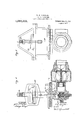
' Figure 1 is a diagrammatic illustration of a locomotive and-tender. havingimy improved heater applied; 'Figure 2 is a partial longitudinal section through the tender; Figure 3 is a, transverse section on the line IIIIII of Figure 2'on an enlarged scale; and Figures 4 and v5are detail'views of the thermostat and valve mechanism employedin my improved heater.
y exhaust steam either from the locomotive cylinders or from the air-compressor or both, and on inspection of Figure 1, it will be seen that the pipe 7 leads fromthe exhaust chamber ofthe cylinders and is connected to the heater by a flexible connection 8, and to the air compressor by a pipe, 9.
Referring now to Figure 2, it will be seen that I have provided a heating chamber, 10, in the bottom of one of the legs of the main water tank, l1, of the tender. Adjacent to heater is preferably designed to use.
either end of the heating chamber-which is shut off from-communication with the main tank-are water chambers 12 and 13. The
chamber, 12, has communication at the top with the main tank, 10, by means of a portor opening 14. A ser-ies of tubes, 15, eX- tend through the heating chamber and open into the water chambers. Steam is admitted to the heating chamber from the pipe 7 through the valve 16 and the pipe 17, said valve being controlled by a thermostat, 18, the operation of which will hereinafter ap- ,pear. The water chamber, 13, 'is provided with a connection 19 for the usual steam mjector, not shown, and with a vent pipe, 20, extending to a point substantially at the normal level of the water in the main tank, and adapted to exhaust the heater fromsair and permit water to flow therein when filling the tender tank. Ii'he end plates 12 and 13 of the heating chamber are preferably made detachable in order to give free access to the tubes 1;.5.' At the rear end of the heating chamber is a condensate tank, 21, from which extends a pipe, 22, leading to the top of the main tank. The waterchamber', 12, is divided into twocompartments by means of the wall, 23, the said compartments having communication with each other at a point substantially belowthe level of the tubes'15. (See Figure 2). By this arrangement, acirculation between the portion of water which is'heated in theitub-es and the cool Water in the tank is prevented, although the water in the tank can flow freely into the heater whenever hot water is being drawn therefrom.
In order that -the temperature of the water may be regulated and maintained at a degree at which the steam injector-will be most efiective' in its operation, I have provided.
a thermostatic valve control for the admis- .sion ofsteam. Referring to Figures 4 and 5, it will be seen that the steam admission valve, 16, is normally held in closed position b means of airpressure admitted to the va ve casing from the main reservoir or other source of supply, by means of the pipe 24 and the port 25, which port is'controlled by the thermostat, 18. The thermostat is mounted in the water chamber, 13. and is provided with a stem, 26, which seats on the port 25 when inclosed position. The stem 26 is normally held in closed position by means of the spring, 29, until the water in the heater reaches the predetermined deate-ant gree, which time vthe action of the heat expands the thermostat proper, 30, and raises the stem 26 from off its seat and thereby permits air pressure to ehter the casing and close the steam valve. Whenthe temperature of the water in the heater falls below the required degree, the thermostat will contract and the spring 29 will seat the stem 26 and close the port 25, thereby permitting the steam valve to open.
The condensate in the heating chamber will collectin the receptacle 21' and upon theadmission of steam into the heating chamber, such condensate will be blown up through the pipe 22 and discharged into the top of the tender tank. It will be noted that the pipe 22 is provided with a looped portion 22, which retains a small amount of condensate after exhaust steam has been admit-ted to the heateruand the steam valve has been closed. The condensate that will collect in this loop portion is sufiicient to prevent the steam from escaping from the heating chamber during the periods when the steam valve is closed.
It will be apparent that my construction is simple and effective in operation and that it is particularly adapted to the requirements of standard structure in tenders. It will also be seen that my improved arrange ment is very-economical in its operation.
Having thus described my invention and illustrated its use, what i claim as new and desire to secure by Letters Patent is the following 1. in combination in a feed water heater, a main tank, a heating chamber therein but having no communication therewith, a water chamber at each end of said heating cham her, one of which communicates with the main tank, a series of tubes extending through the heating chamber and openinginto the water chambers, a steam inlet to the heating chamber and a discharge outlet from one of the water chambers.
2. in combination in a feed water heater,
a main tank, an elongated heating chambermounted therein at a point below the level of the water line, said chamber having no communication with the tank, a water chamber adjacent the forward end of the heating chamber, a water chamber adjacent the rearward end of the heating chamber opening into the main tanlr, and a series of tubes ea tending through the heatin chamber and opening into the water chambers, the said rear water chamber being composed of two communicating compartments opening into each other at their lower portions.
3. A feed water heater for locomotive ten ders comprising a heating chamber located in the bottom. of the tender tank, a water chamber at the forward end of the heating chamber, a water chamber at the rearward end thereof communicating with the main tender tank, a pluralit of tubes extending through the heating c amber and opening into the water chambers, an outlet from the forward water chamber, a wall dividing the rear water chamber into two compartments communicating with each other at a point below the level of the tubes, and means tor admitting steam to the heating chamber.
4. In combination in a feed water heater, a main tank, a heating chamber therein, a water chamber at each end of said heating chamber, one ot which communicates with the main tank, a series of tubes extending through the heating chamber and opening into the water chambers, a removable plate for one of the water chambers opposite the ends of the tubes arranged to give access to the tubes when the plate is removed, a steam inlet to the heating chamber, and a discharge outlet :trom one of the water chambers.
5. In combination in a feed water heater, a main tank, a heating chamber therein, a water chamber at each end oi said heating chamber, one of which commimicates with the main tank, a series of tubes extending through the heating chamber and opening into the water chambers, a removable plate for each of the water chambers opposite the ends of the tubes in such chambers, and arranged to give access to the end of the tubes when the plates'are removed, a steam inlet to the heating chamber, and a disgharge outlettrom one of the water chamere.-
l'n testimony whereof l have hereunto signed my name in the presence or the two subscribed witnesses.
HENRY H. VAUGHAN.
Witnesses:
L. A. Mrnns, JULIAN H. Knnnro.
Priority Applications (1)
| Application Number | Priority Date | Filing Date | Title |
|---|---|---|---|
| US63178311A US1069360A (en) | 1911-06-07 | 1911-06-07 | Feed-water heater. |
Applications Claiming Priority (1)
| Application Number | Priority Date | Filing Date | Title |
|---|---|---|---|
| US63178311A US1069360A (en) | 1911-06-07 | 1911-06-07 | Feed-water heater. |
Publications (1)
| Publication Number | Publication Date |
|---|---|
| US1069360A true US1069360A (en) | 1913-08-05 |
Family
ID=3137597
Family Applications (1)
| Application Number | Title | Priority Date | Filing Date |
|---|---|---|---|
| US63178311A Expired - Lifetime US1069360A (en) | 1911-06-07 | 1911-06-07 | Feed-water heater. |
Country Status (1)
| Country | Link |
|---|---|
| US (1) | US1069360A (en) |
-
1911
- 1911-06-07 US US63178311A patent/US1069360A/en not_active Expired - Lifetime
Similar Documents
| Publication | Publication Date | Title |
|---|---|---|
| US1069360A (en) | Feed-water heater. | |
| US1078623A (en) | Water-heating apparatus. | |
| US1596423A (en) | Water-deaerating apparatus | |
| US406512A (en) | Feed-water heater | |
| US1036826A (en) | Water-heating apparatus. | |
| US2255904A (en) | Suction-vapor heating system | |
| US1591822A (en) | Heater | |
| US1902969A (en) | Feed water heater for locomotives | |
| US1554258A (en) | Boiler-feed-water heater | |
| US384540A (en) | William oliphant | |
| US2230087A (en) | Boiler | |
| US938573A (en) | Feed-water heater. | |
| US1698787A (en) | Feed-water heater | |
| US586968A (en) | Arthur graham glasgow | |
| US569637A (en) | Edward e | |
| US1657319A (en) | Water-tube boiler | |
| US503745A (en) | Apparatus | |
| US474404A (en) | prescott | |
| US153951A (en) | Improvement in automatic boiler-feeders | |
| US1014822A (en) | Water-heating apparatus. | |
| US1117947A (en) | System and apparatus for blowing off, washing, and filling locomotive boilers. | |
| US350820A (en) | Teeeitoey | |
| US1109352A (en) | Boiler washing and filling system. | |
| US880806A (en) | Heating system. | |
| US1108633A (en) | Means for heating boiler feed-water. |