US1069303A - Card-holder for time-recorders. - Google Patents
Card-holder for time-recorders. Download PDFInfo
- Publication number
- US1069303A US1069303A US67882312A US1912678823A US1069303A US 1069303 A US1069303 A US 1069303A US 67882312 A US67882312 A US 67882312A US 1912678823 A US1912678823 A US 1912678823A US 1069303 A US1069303 A US 1069303A
- Authority
- US
- United States
- Prior art keywords
- card
- guide
- holder
- card holder
- machine
- Prior art date
- Legal status (The legal status is an assumption and is not a legal conclusion. Google has not performed a legal analysis and makes no representation as to the accuracy of the status listed.)
- Expired - Lifetime
Links
- 238000010276 construction Methods 0.000 description 3
- 244000221110 common millet Species 0.000 description 2
- 230000008878 coupling Effects 0.000 description 1
- 238000010168 coupling process Methods 0.000 description 1
- 238000005859 coupling reaction Methods 0.000 description 1
- 238000006073 displacement reaction Methods 0.000 description 1
- 230000037431 insertion Effects 0.000 description 1
- 238000003780 insertion Methods 0.000 description 1
- 238000004890 malting Methods 0.000 description 1
- 239000002184 metal Substances 0.000 description 1
- 210000002105 tongue Anatomy 0.000 description 1
Images


Classifications
-
- G—PHYSICS
- G07—CHECKING-DEVICES
- G07C—TIME OR ATTENDANCE REGISTERS; REGISTERING OR INDICATING THE WORKING OF MACHINES; GENERATING RANDOM NUMBERS; VOTING OR LOTTERY APPARATUS; ARRANGEMENTS, SYSTEMS OR APPARATUS FOR CHECKING NOT PROVIDED FOR ELSEWHERE
- G07C1/00—Registering, indicating or recording the time of events or elapsed time, e.g. time-recorders for work people
- G07C1/02—Registering, indicating or recording the time of events or elapsed time, e.g. time-recorders for work people not involving the registering, indicating or recording of other data
- G07C1/04—Registering, indicating or recording the time of events or elapsed time, e.g. time-recorders for work people not involving the registering, indicating or recording of other data wherein the time is indicated in figures
- G07C1/06—Registering, indicating or recording the time of events or elapsed time, e.g. time-recorders for work people not involving the registering, indicating or recording of other data wherein the time is indicated in figures with apparatus adapted for use with individual cards
Definitions
- WITN ESSES
- This invention relates to recording machines and has for its object a particularly simple and e'lfieient means for automatically controlling the positions of records on the record sheets or cards used in connection with the machine; and it consists in the combinations and constructions hereinafter set forth and claimed.
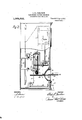
- Figure 1 is a front elevation of one formof iecordmg machine in connection with which my invention may be used.
- Fig. 2 is a side elevation, partly in section, of the machine shown in Fig. 1.
- Figs. 3 and 4 are plan views, partly broken away, of one form of card holder. contiguous portions of the recording machine being shown, the mechanism associated with the holder being shown in its position occupied when the holder is approaching the limit of its movement; in Fi 3, and when the holder is at the limit of its movement, in Fig. 4.
- Fig. 5 is an edge view of the cardholder, contiguous parts of the recording machine being shown.
- Fig. (i is a sectional. view throughthe body of the card holder showing the mechanism therein.
- FIG. 6 is a detail View of one of the movable stops associated with each card lmlder.
- Figs. 7 and 8 are plan views, similar to Figs. 3 and 4, of a slightly modified form of card holder, the body of the card holder in Fig. 8 being shown in section.
- Fig. 9 is an edge view similar to Fig. 5, of the card holder seen in l igs. 7 and 8.
- Fig. 10 is a different form of card holder from that shown in Figs. 3, 4, 7 and 8.
- Figs. 11 and 12 are plan views-similar to Figs. 3 and 4, showing the means associated with the machine for operating the resetting imichanisin on the card holder.
- Fig. 13 is an edge view, looking upwardly, of parts seen in Figs. '11 and 12, parts being omitted.
- This invention comprises, a card holder for the individual record cards of recording machines having card guides, there being one holder for each workman, and such holders being detachable from the machine, and mechanism for automatically determining successive ositions of the card holder relatively to t e guide, comprising means carried by'the card holder.
- the recording machine may be of any desirable form, size and construction and is here shown as a time recorder comprising a time movement 1, a printing element, as type wheels 2, 3 connected to the time movement to be operated thereby by means of shafts 4,5 connected respectively to the time movement, and to one of the wheels as 2, and miter gears 6 connectingthe shafts.
- the other type wheel 3 is actuated by the wheel 2 connected to the shaft 5, in any well known manner.
- the shaft 5 is formed of two sections having their contiguous ends connected by a universal clutch of well known construction operable to permit a slight depression of the part of the shaft associated with the type wheel 2 during the printing operation.
- the universal coupling is composed of three plates having interfitt-ing tongues and grooves extending diametrically of the plates at diiferent angles as will be understood by tho skilled in the art.
- the time recorder is also formed with a guide 7 inelosing a slot for the card holder and having a face plate 8 on the front face of the time recorder, the guide 7 serv- 7 ing as a platen.
- a suitable inking ribbon 9 1s interposed between the type wheels and the platen and the type wheels are movable toward and from the platen to eifect the printing of a record on the card-held by the card holder in the guide 7.
- This movement of the type wheels is here shown as effected by means of a handle 10 located on the front side of the machine and connected to the oscillating frame 11 carrying the type wheels, by means of a link 12, angle lever 13 and link 14-, the link 12 connecting the handle 10 and one arm of the angle lever 13.
- the frame 11 is supported by arms 15 pivoted at their opposite ends respectively at 16 and 17 to the frame 11 and to a bracket 18 supported by the rear wall of the casing of the machine.
- the downward movement of the frame is against the action of. the returning spring 19.
- the mechanism for automatically determining the successive positions of the card holder relatively to the guide 7, thatis into the guide comprises a series of successively effective stops 20 carried by each card holder 21 and means preferably associated with the machine and arranged to engage the foremost effective stop and limit the movement of the card holder into the guide and move such stop out of effective position and expose the next stop to the action of such means during the next positioning, of the card holder relatively to the guide.
- card holder 21 comprises a body 22 and a fiat card support 23, the body and card support being flat and arranged in alinement, and the body confining a chamher in which is located the series of abutments 20.
- abutments are preferably movable independently of each other, that is, all are not formed on a single movable part, and said abutments 20 are movable in guides 24 extending in a direction at a right angle to the movement of the card holder into the guide 7, Fig. 6, the abutments .being arranged with their engaging ends exposed at an open side edge of the body 22.
- the abutments are held in either their normal or their shifted positions by means of impositive locking means as spring brakes 25 carried thereby and bearing against the walls of the guides 24.
- the means associated with the machine for shifting the abutments one by one, is here shown as a. pawl 26 pivoted at one side of the guide 7 and arranged with its pivot 27 extending crosswise of the guide and having its engaging end 2S'projecting through the open edge of the body 22 into position to engage the angular surface 29 at the end of each stop 20.
- the card support 23 is provided with suitableopposite marginal guides 33 under which the edges of the card moves when the card is being inserted in, or removed from, the card holder, and usually the body 22 projects laterally beyond the edge of the card support so that the stops 20 normally project laterally beyond one edge of the card support 23, as seen at the left of Figs. 3, 4, 7 and 8.
- the stops 20 are reset by means located within the chamber of the body 22, and as here shown, said means comprises a member 34 slidable rectilinearly in the body 22 and having arms 35 engaging opposite edge walls of such chamber, said member being arranged to engage the rear ends of all the stops 20 and also to limit the inward movement of such stops 20.
- the resetting member 34 is held from free movement by a spring-pressed brake 36 carried by one of the arms 35 en gaging one of the edge walls of the body 22.
- the resetting member 34 may be moved in any suitable manner, as by an operating lever 37 pivoted at 38 between its ends to the walls of the body 22 and having one arm thereof engaged with the member 34 and the other arm thereof exposed through the open edge of the body 22 in position to be operated by hand, or by means associated with the machine, as hereinafter set forth.
- the member 34 is in its normal position, it is held by the lever 37 from movement toward said lever for the reason that the member 34 engages the hub of the lever 37 as clearly seen in Fig. (3.
- the resetting member prevents the stops 20 from being pressed inwardly beyond their inefi ective positions.
- the stops 20 control the position of successive records transversely of the card and prevent two records being made on the same space and cause successive records to be arranged side by side, and preferably these records are the successive records of the workman during one day. For instance, on the card illustrated in Figs. 3 and 4, eight successive records can be made side by side during one day.
- the type wheels 2, 3 may be shifted. axially by hand, or automatically, in any well known manner, or the card guide may be shifted either by hand or automatically as will be understood by those skilled in the art.
- the card guide 7 as adjustable laterally by hand, the face plate 8 of the guide being formed with a handle 39, Fig.
- the guide may be shifted laterally from the front of the machine in the direction indicated by the arrow, the guide being held in its adjusted position in any suitablemanner, as by a springpressed pin 40 for entering any one of a series of holes 41 in the face plate of said guide 7.
- the card support 23 may be shifted relatively to the body 22, and preferably such shifting is effected at the same time that the stops 20 are being reset.
- the body 22 is of sutH- cient width to permit the day to day shifting of the card support 23, and is formed with a groove or channel 42 in one edge thereof in which the margin 43 of the card support projects, such margin being bent in the form shown in Fig. 9, in order to snugly fit the channel 42, the channel having a contracted entrance 44 for holding the card support in position.
- the card support 23 is shifted by the resetting member 34 which is shown as carrying a pawl 45 projecting through the bottom of the channel 42 into position to engage a rack 46 formed on the edge of the card holder 23.
- the resetting member 34 is operated by means of a link 47 pivoted at 43 to the member 34 and having a handle 49 movable in an arc-shaped slot 50 formed in the front face of the body 22, the slot being concentric with the axis 43, and units side farthest removed from such axis, being provided with notches or radially extending slots 51 corresponding in number to the days of the week represented on the card.
- the card support is returned by hand to its starting position in engagement with a shoulder 23, and the pawl 45 is withdrawn out of engagement with the rack 46 to permit the return of the support 23, by moving the member 34 inwardly by means of the handle 49 until.
- the pawl 45 engages a surface 45 at one end of the opening in the bottom of the channel 42 for said pawl, which surface holds the pawl out of engagement with the rack.
- the card support is prevented from unintentional displacement to the porting surface.
- this form of card holder which may be used to hold cards upon which a large number of registrations are to be made or for cost keeping, space is provided for a large number of stops without malting the card holder longer than the card used.
- the lever 37 operating the resetting member 34 may be operated either by "hand at the beginning or end of each day, or as seen in Figs. 11, 12 and 13 may be operated by means associated with the clock, this means being here shown as a shoulder 52 which is movable into the path of the end 53 of the lever 37 so that during the first insertion of the card holder into, the guide the end 53 of such lever will engage the shoulder 52 causing the lever to move the resetting member 34, this shoulder being set in operative position during a certain period oftime as for instance, from shortly before the beginning of the working period until shortly after.
- the shoulder may be controlled in its movement into and out of operative. position either automatically by the clock, or may be set by hand by an authorized person having access to the clock.
- the shoulder 52 is carried by one arm of a hand operated lever 54 pivoted at 55. between its ends to the card guide 7 and having a button or handle 56 at its opposite end.
- the shoulder 52 might be operated from the time movement.
- it may 7 act as a stop for determining the first position of the card holder, that is the stop 20 for determining the first position of the card holder may be dispensed with;
- My card holder can be built for the most part of sheet metal in a durable and inexpensive manner. and the mechanism carried by the card holder is simple, and economical of nanufacture and cannot readily get out of order.
- one card holder is assigned to each workman and when he enters or leaves the factory or begins or finishes a job, he places Ill the card holder in the card guide 7 and 7 shown in Figs. 3 and 4 is used, the lever 37 is operated to reset the abutments either'at the end or beginning of each day and the card guide shifted laterally by hand, in case no automatic means for shifting such guide or the type wheels is employed.
- the casing having an opening, and mechanism for automatically determining successive positions of the card holder relatively to the guide of the recording machine, said mechanism comprising means located in the chamber and operable through the opening, substantially as and for the purpose described.
- a card holder for the individual record cardsv of recording machines having card guides, the holder being detachable from the machine. and comprising a flattened casing confining a chamber, the chamber being open at one edge, and mechanism for automatically determining successive positions of the card holder relatively to the guide of the recording machine, said mechanism comprising means located in the chamber and exposed to,and operable through, such open edge, substantially as and for the purpo'sespecified.
- a card holder for the individual record cards of recording machines having card guides, the holder being detachable from the machine and comprising a flat card support, and a casing alined with the card support and confining a chamber, and mechanism for automati-- matically determining successive positions of the card holder relatively to the guide of the recording machine, said mechanism comprising a series of consecutively arranged stops carried by the flat portion. of the card holder, substantially as and for the purpose described.
- a recording machine having a card guide, a holder for in dividual record cards.
- the holder being detachalole from the machine and movable relatively to the guide. and comprising a flattened casing confining a chamber, the casing having an opening, a series of successively etlective stops located in the chamber and having their engaging portions aecessihle through such opening, and means associated with the machine for engaging the foremost effective stop through such opening and limiting the movement of the card holder relatively to the guide and displacing said stop and exposing the next citectivo stop in position to be engaged by said means during the next positioning of the card holder relatively to the guide, substantially as and for the purpose specified.
- a recording machine having a card guide, a holder for individual record cards, the holder'being detachable from the machine and movable rel-" ativelv to the guide, and comprising a fiattened casing confining a chamber, the chamber being open at one edge, a series of successively etl'ective stops located in the chamber and havii'ig their engaging portions accessible through such open edge.
- a recording machine havinga card guide, a holder for individual record cards, the holder being ,de tachable from the machine and movable relatively to the guide, a series of successively etlective stops Carried by the card holder, a movable pawl associated with the machine contiguous to the guide, the pawl projecting into the path of the card holder in position to engage the foremost effective stop and move such stop out of effective position, and ex 'iose the next stop to the action of the pawl during the next positioning of the card holder relatively to the guide, and a stop for limiting the movement of the pawl, substantially as and for the purpose specitied.
- a recording ma chine having a card guide, a holder for individual record cards, the holder being detachablc from the machine and movable relatively to the guide, a series of successively ei'l'ective movable stops carried by the card holder, a pivoted pawl associated with the machine and arranged to project into the path of the card holder to engage the foremost effective stop, the engaging end of the pawl being movable in an arc curving in the direction of movement of each stop for moving such stop out of effective position, and exposing the next stop to the action of the pawl during the next positioning of the card holder relatively to the guide, and a stop for limiting the pivotal movement of the pawl, substantially as and for the purpose described.
- a recording machine having a card guide, a holder for individual record cards, the holder being detachable from the machine and movable relatively to the guide, and comprising a flattened casing confining a chamber, the chamber being open at one edge,-a series of successively effective stops located in the chamber and having their engaging port-ions accessible through such open edge, a pivoted I I 1 t pawl associated With the machine and arranged With its axisextending-crosswise of the plane of movement of the card holder into the guide, and the pawl being arranged at one side of the guide and having its free end projecting into the path of the card holder into position to enter through the open edge of the chamber to engage the foremost efi'ective stop and move the same out of effective position, and expose the next effective stop into position to be en gaged by such pawl during the next positioning of the card holder relatively to the guide, and a stop for limiting the pivotal -the individual record cards of recording movement of the pawl,
- a card holder for the individual record cards of recording machines having card guides, the holder being detachable from the machine and comprising a flat card support and a flattened casing alined with the card support and confining a chamber, the casing having an opening, and mechanism for automatically determining successive positions of the card holder relatively to the guide of the recording machine, said mechanism comprising a series of successively efiective stops located in the chamber, and having their engaging portions accessible through such opening, substantially as and for the purpose described.
- mechanism for automatically determining successive positions of the card holder relatively to the guide of the recording machine comprising a series-of successively effective stops located in the chamber for determining successive positions of the card holder relatively-to the guide of the recording machine, the stops having their engaging portions accessible and operable through such opening, the stops being displaceable one by one through such opening during "successive 'positionings of the card holder relatively to the guide of the recording machine, and resetting means in the chamber comprising a slide common to all of the stops and engaging edge walls of the chamber, substantially as and for the purpose described.
- a card holder for the individual record cards of recording machines having card guides the holder being detachable from the machine, and mechanism for automatically determining successive positions of the card holder relatively to the guide of the recording machine, said mechanism comprising a series of'su-c- (-essivelv efiective movable stops carried by the card holder for determining the extent of movement of the card relatively to the guide of the recording machine during suceessive positionings of the card holder, the stops being displaceable one by one, during successive positionings oi the card holder relatively to the guide of the recording machine, and resetting means carried by the card holder and comprising a pivoted lever, substantially as and for the purpose specitied.
- a card holder for the individual recr ord cards of recording machines having card guides, the holder being detachablefrom the machine and provided with a chamber, and mechanism for automatically determining successive positions of the card holder relatively to the guide of the recording machine, said mechanism comprising a series of independently movable and successively effective stops in the chamber for determining successive positions of the and holder relatively to the guide of the recording machine, the stops being displaceable one by one during successive positionings of the card holder relatively to the.
- stop resetting means comprising a rectilinear-1y movable member slidable in the chamber and being common to all of the stops, and an operating lever pivoted between its ends and having one arm thereof arranged to cooperate with said member, substantially as and for the purpose described.
- a card holder for the individual rec ord cards of recordingmachines having card guides, the holder being detachable from the machine and movable relatively to the guide of the recording machine, and comprising a body, and a card support adjust able relatively to the body, substantially as and for the purpose specified.
- a card holder for the individual record cards of recording machines having card guides, the holder being detachable from the machine and movable relatively to the guide of the recording machine, and comprising a body, and a card support adjustable relatively to the body, and means carried by the body for adjusting the card support, sul stantially as and for'the purpose set forth.
- a card holder for the individual record cards of reco ding machines having card guides, the holder being detachable from the machine and movable relatively to the guide of the recording machine, and comprising a body anda card support slidable along the body, substantially as and for the purpose described.
- a card holder for the individual rec- 0rd cards of recording machines having card guides, the holder being detachable from the machine and movable relatively to the guide of the recording machine, and comprising a body, and a card support adjustable relatively to the body and being formed with a rack and means carrie d by the body for coacting with the rack for shifting the card support relatively to the body, substantially as and for the purpose set forth.
- a card holder for the individual record cards of recording machines having card guides comprising a body in the form of a flattened casing confining a chamber, the body being formed with an external channel at one end, and a card support having a portion fitting and slidable in the channel and provided with a rack, and means for shifting the card holder relatively tothe body and comprising means located within the chamber and having a pawl working through the bottom record cards of recording machines having card guides, the holder being detachable from the machine and movable relatively to the guide of the recording machine, and comprising a body, a card support shiftable relatively to the body, a series of successive 'sively effective stops carried by the body,
- the stops being displaceable one by one during successive positionings of the card holder relatively to the guide of the recording machine, and means carried by the body for resetting the stops and for shifting the card support relatively to the body in one operation, substantially as and for the,purpose set forth.
- a card holder for the individual record cards of recording machines having card "guides, the holder being detachable from the machine and movable relatively to the guide of the recording machine, and comprising a body, a card support shiftable relatively to the body, a series of successively efiect-ive stops carried by the body, the stops being displaceable, stop resetting means carried by the body and comprising a movable member common to all of the stops, means associated with said member for coacting with the card support for shifting the same, and an operating element coacting with said member, substantially as and for the purpose described.
- a casing and printing mechanism associated therewith including an imprint making element, a card holder for an individual record card, the holder being insertible into the casing for locating the card in relation to the imprint making element and being removable from the casing, and a mechanism for automatically reg istering successive spaces on the card with the imprint making element'comprising a plurality of independently movable abutments associated with the card holder, substantially as and for the purpose specified.
- a card carrier comprising two sections relatively movable in reference to each other, means associated with one of the sections for engaging the card, and a plurality of shiftable stop surfaces associated with the other section, substantially as and for the purpose described.
Landscapes
- Physics & Mathematics (AREA)
- General Physics & Mathematics (AREA)
- Control Of Vending Devices And Auxiliary Devices For Vending Devices (AREA)
Description
, c. E. TOMLINSON. CARD HOLDER FOR TIME REGORDERS.
APPLICATION TILED IEB.20, 1912,
Patented Aug. 5, 1913.
5 SHEETS-SHEET 1.
wnuassgs:
Patented Aug. 5, 1913.
6 SHEETS-SHEET 2.
I II III! aww I ATTORNEYS G. B. TOMLINSON.
CARD HOLDER FOR TIME REGORDERS.
APPLIUATION FILED FEB-20, 1912. 1,069,303.
///////I//I//Y/I/////', M i
' WITNESSES:
O. E. TOMLINSON.
CARD HOLDER FOR TIME REGORDERS.
APPLICATION FILED $33.20, 1912.
Patented Aug. 5, 1913.
6 SHEETSSHEIET 3.
3:2 I i: 5%. l I 2 a 3: 3 M3 v ATTORN EYS O. E. TOMLINSON.
CARD HOLDER FOR TIME RECORDERS.
APPLICATION FILED FEB.20,1912.
Patented Aug. 5, 1913.
5 SHEETSSHEET 4.
WITN ESSES:
APPLICATION FILED FEILZO, 1912.
Patented Aug. 5, 1913.
5 SHEETS-SHEET 5 WITN ESSES J 7/; g ww/ ATTORNEYS UNITED STATES PATENT OFFICE. i
CHARLES E. TOMLINSON, OF SYRACUSE, NEW YORK, ASSIGNOR, BY ME SNE ASSIGN- MENTS, TO INTERNATIONAL TIME RECORDING COMPANY OF NEW YORK, OF ENDI- CO'IT, NEW YORK, A CORPORATION OF NEW YORK.
CARD-HOLDER FOR TIME-BECORDERS.
Specification of Letters Patent.
?atented Aug. 5,1913.
Application filed February 20, 1912. Serial No. 678,823.
To a. who-11bit may concern:
lie it known that 1, CHARLES E. TOMLIN- mm. of Syracuse, in the county of Onondaga and State of New York, have invented a certain new and useful Card-Holder for Tiinc-Recorders, of which the following is a specification.
This invention relates to recording machines and has for its object a particularly simple and e'lfieient means for automatically controlling the positions of records on the record sheets or cards used in connection with the machine; and it consists in the combinations and constructions hereinafter set forth and claimed.
in describing this invention reference is had to the accompanying drawings in which like characters designate corresponding parts in all the views.
Figure 1 is a front elevation of one formof iecordmg machine in connection with which my invention may be used. Fig. 2 is a side elevation, partly in section, of the machine shown in Fig. 1. Figs. 3 and 4 are plan views, partly broken away, of one form of card holder. contiguous portions of the recording machine being shown, the mechanism associated with the holder being shown in its position occupied when the holder is approaching the limit of its movement; in Fi 3, and when the holder is at the limit of its movement, in Fig. 4. Fig. 5 is an edge view of the cardholder, contiguous parts of the recording machine being shown. Fig. (i is a sectional. view throughthe body of the card holder showing the mechanism therein. Fig. 6 is a detail View of one of the movable stops associated with each card lmlder. Figs. 7 and 8 are plan views, similar to Figs. 3 and 4, of a slightly modified form of card holder, the body of the card holder in Fig. 8 being shown in section. Fig. 9 is an edge view similar to Fig. 5, of the card holder seen in l igs. 7 and 8. Fig. 10 is a different form of card holder from that shown in Figs. 3, 4, 7 and 8. Figs. 11 and 12 are plan views-similar to Figs. 3 and 4, showing the means associated with the machine for operating the resetting imichanisin on the card holder. Fig. 13 is an edge view, looking upwardly, of parts seen in Figs. '11 and 12, parts being omitted.
This invention comprises, a card holder for the individual record cards of recording machines having card guides, there being one holder for each workman, and such holders being detachable from the machine, and mechanism for automatically determining successive ositions of the card holder relatively to t e guide, comprising means carried by'the card holder.
The recording machine, with which my invention may be used, may be of any desirable form, size and construction and is here shown as a time recorder comprising a time movement 1, a printing element, as type wheels 2, 3 connected to the time movement to be operated thereby by means of shafts 4,5 connected respectively to the time movement, and to one of the wheels as 2, and miter gears 6 connectingthe shafts. The other type wheel 3 is actuated by the wheel 2 connected to the shaft 5, in any well known manner. The shaft 5 is formed of two sections having their contiguous ends connected by a universal clutch of well known construction operable to permit a slight depression of the part of the shaft associated with the type wheel 2 during the printing operation. The universal coupling is composed of three plates having interfitt-ing tongues and grooves extending diametrically of the plates at diiferent angles as will be understood by tho skilled in the art. The time recorder is also formed with a guide 7 inelosing a slot for the card holder and having a face plate 8 on the front face of the time recorder, the guide 7 serv- 7 ing as a platen. A suitable inking ribbon 9 1s interposed between the type wheels and the platen and the type wheels are movable toward and from the platen to eifect the printing of a record on the card-held by the card holder in the guide 7. This movement of the type wheels is here shown as effected by means of a handle 10 located on the front side of the machine and connected to the oscillating frame 11 carrying the type wheels, by means of a link 12, angle lever 13 and link 14-, the link 12 connecting the handle 10 and one arm of the angle lever 13. I
and the link 14- conneeting the other arm of the angle lever and the frame 11, and being connected to the frame in any suitable manner. The frame 11 is supported by arms 15 pivoted at their opposite ends respectively at 16 and 17 to the frame 11 and to a bracket 18 supported by the rear wall of the casing of the machine. The downward movement of the frame is against the action of. the returning spring 19.
The means for efiecting the movement toward and from the platen forms no part of this invention, and as various means for effecting such .movement are well known,
further description is thought to be unnecessary.
The mechanism for automatically determining the successive positions of the card holder relatively to the guide 7, thatis into the guide, comprises a series of successively effective stops 20 carried by each card holder 21 and means preferably associated with the machine and arranged to engage the foremost effective stop and limit the movement of the card holder into the guide and move such stop out of effective position and expose the next stop to the action of such means during the next positioning, of the card holder relatively to the guide.
As seen in Figs. 3, 4, 7 and 8 each, card holder 21 comprises a body 22 and a fiat card support 23, the body and card support being flat and arranged in alinement, and the body confining a chamher in which is located the series of abutments 20. These abutments are preferably movable independently of each other, that is, all are not formed on a single movable part, and said abutments 20 are movable in guides 24 extending in a direction at a right angle to the movement of the card holder into the guide 7, Fig. 6, the abutments .being arranged with their engaging ends exposed at an open side edge of the body 22. The abutments are held in either their normal or their shifted positions by means of impositive locking means as spring brakes 25 carried thereby and bearing against the walls of the guides 24. The means associated with the machine for shifting the abutments one by one, is here shown as a. pawl 26 pivoted at one side of the guide 7 and arranged with its pivot 27 extending crosswise of the guide and having its engaging end 2S'projecting through the open edge of the body 22 into position to engage the angular surface 29 at the end of each stop 20. Owing to the posit-ion of the pivot 27-and the engaging end 28 of the pawl, said end moves in an arc curving in the direction of movement of the stops 20, so that when the card holder is inserted in the guide 7, the pawl 26 will engage the foremost effective stop 20. and shift the same from the position shown in Fig. 3, to that shown in Fig. 4, and when the stops reach the position v of the foremost stop shown in Fig. 4, further pivotal movement of the pawl 26 is prevented by a stop 30 on the guide. The pawl is returned to its operative position into engagement with a pin 31, by a spring 32. .The movement of the stops 20 is limited as hereinafter set forth. The card support 23 is provided with suitableopposite marginal guides 33 under which the edges of the card moves when the card is being inserted in, or removed from, the card holder, and usually the body 22 projects laterally beyond the edge of the card support so that the stops 20 normally project laterally beyond one edge of the card support 23, as seen at the left of Figs. 3, 4, 7 and 8. The stops 20 are reset by means located within the chamber of the body 22, and as here shown, said means comprises a member 34 slidable rectilinearly in the body 22 and having arms 35 engaging opposite edge walls of such chamber, said member being arranged to engage the rear ends of all the stops 20 and also to limit the inward movement of such stops 20. The resetting member 34 is held from free movement by a spring-pressed brake 36 carried by one of the arms 35 en gaging one of the edge walls of the body 22. The resetting member 34 may be moved in any suitable manner, as by an operating lever 37 pivoted at 38 between its ends to the walls of the body 22 and having one arm thereof engaged with the member 34 and the other arm thereof exposed through the open edge of the body 22 in position to be operated by hand, or by means associated with the machine, as hereinafter set forth. \Vhen the member 34 is in its normal position, it is held by the lever 37 from movement toward said lever for the reason that the member 34 engages the hub of the lever 37 as clearly seen in Fig. (3. Thus the resetting member prevents the stops 20 from being pressed inwardly beyond their inefi ective positions. The stops 20 control the position of successive records transversely of the card and prevent two records being made on the same space and cause successive records to be arranged side by side, and preferably these records are the successive records of the workman during one day. For instance, on the card illustrated in Figs. 3 and 4, eight successive records can be made side by side during one day.
For the purpose of relatively positioning the card holder and the type wheels to shift the records from the space of one day to the space of the next as frornMonday to Tuesday or from Tuesday to lVednesday, etc... either the type wheels 2, 3 may be shifted. axially by hand, or automatically, in any well known manner, or the card guide may be shifted either by hand or automatically as will be understood by those skilled in the art. I have here shown the card guide 7 as adjustable laterally by hand, the face plate 8 of the guide being formed with a handle 39, Fig. 1, by means of which the guide may be shifted laterally from the front of the machine in the direction indicated by the arrow, the guide being held in its adjusted position in any suitablemanner, as by a springpressed pin 40 for entering any one of a series of holes 41 in the face plate of said guide 7. However, instead of providing the machine with movable parts for effecting the shifting of the card from day to day, the card support 23 may be shifted relatively to the body 22, and preferably such shifting is effected at the same time that the stops 20 are being reset.
In Figs. 7 and 8, the body 22 is of sutH- cient width to permit the day to day shifting of the card support 23, and is formed with a groove or channel 42 in one edge thereof in which the margin 43 of the card support projects, such margin being bent in the form shown in Fig. 9, in order to snugly fit the channel 42, the channel having a contracted entrance 44 for holding the card support in position. In the embodiment of my invention shown in Figs. 7 and 8, the card support 23 is shifted by the resetting member 34 which is shown as carrying a pawl 45 projecting through the bottom of the channel 42 into position to engage a rack 46 formed on the edge of the card holder 23. in this form of my invention the resetting member 34 is operated by means of a link 47 pivoted at 43 to the member 34 and having a handle 49 movable in an arc-shaped slot 50 formed in the front face of the body 22, the slot being concentric with the axis 43, and units side farthest removed from such axis, being provided with notches or radially extending slots 51 corresponding in number to the days of the week represented on the card.
In operation, at the end of each day the handle 49 is moved inwardly out of one slot 51, thus causing the member 34 to reset the stops 20, the handle is then moved in the slot 50 until itis alined with the next notch 51 and then said handle 49 is pulled outwardly into such next notch. During the reciprocating movement of the member 34, efiected by the movement of theuhandle 49 out of one notch in one direction into another notch in the other direction, "the pawl 45 moves in one direction and takes hold of a teeth of the rack 46 and then moves in the opposite direction advancing the card support 23 one step laterally in the channel 42. The card support is returned by hand to its starting position in engagement with a shoulder 23, and the pawl 45 is withdrawn out of engagement with the rack 46 to permit the return of the support 23, by moving the member 34 inwardly by means of the handle 49 until. the pawl 45 engages a surface 45 at one end of the opening in the bottom of the channel 42 for said pawl, which surface holds the pawl out of engagement with the rack. The card support is prevented from unintentional displacement to the porting surface. In this form of card holder which may be used to hold cards upon which a large number of registrations are to be made or for cost keeping, space is provided for a large number of stops without malting the card holder longer than the card used. As before stated the lever 37 operating the resetting member 34 may be operated either by "hand at the beginning or end of each day, or as seen in Figs. 11, 12 and 13 may be operated by means associated with the clock, this means being here shown as a shoulder 52 which is movable into the path of the end 53 of the lever 37 so that during the first insertion of the card holder into, the guide the end 53 of such lever will engage the shoulder 52 causing the lever to move the resetting member 34, this shoulder being set in operative position during a certain period oftime as for instance, from shortly before the beginning of the working period until shortly after. The shoulder may be controlled in its movement into and out of operative. position either automatically by the clock, or may be set by hand by an authorized person having access to the clock. As here shown the shoulder 52 is carried by one arm of a hand operated lever 54 pivoted at 55. between its ends to the card guide 7 and having a button or handle 56 at its opposite end. However, as time cams and means for automatically operating devices by time controlled mechanism is common in the art, obviously the shoulder 52 might be operated from the time movement. When the shoulder 52 is employed, it may 7 act as a stop for determining the first position of the card holder, that is the stop 20 for determining the first position of the card holder may be dispensed with; and
during the movement of the card holder into the guide, the end 53 of the reset-ting lever 37 would engage the shoulder 52, and be moved until the member 34 abuts against the inner ends of the stop guides 24, thus limiting the movement of the card holder into the guide 7. My card holder can be built for the most part of sheet metal in a durable and inexpensive manner. and the mechanism carried by the card holder is simple, and economical of nanufacture and cannot readily get out of order.
In use, one card holder is assigned to each workman and when he enters or leaves the factory or begins or finishes a job, he places Ill the card holder in the card guide 7 and 7 shown in Figs. 3 and 4 is used, the lever 37 is operated to reset the abutments either'at the end or beginning of each day and the card guide shifted laterally by hand, in case no automatic means for shifting such guide or the type wheels is employed.
Generic claims for certain features disclosed herein, but not claimed broadly, are
contained in certain of my pending applications, among others, application filed August 27, 1908, Sr. No. 450,469 and application filed August 10, 1911, Sr. No. 643,286.
What I claim is:
1. The combination of a card holder for the individual record cards of recording machines having card guides, the holder being detachable from the. machine and provided with a flat portion, and mechanism for automatically determining successive positionsof the card holder relatively to the guide of the recording machine, said mechanism comprising means carried by the flat portion of the card holder, substantially as and for the purpose specified.
2. The combination of a card holder for the individual record cards of'recording machines ha ving card guides, the holder being detachable from the machine and provided with a chamber, and mechanism for automatically determining successive positions of thecard holder relatively to the guide of the recording machine, said mechanism comprising means located in said chamber, substantially as and for the purpose set forth.
3. The combination of a card holder for the individual record cards of recording machines having card guides, the holder being detachable from the machine and com prising a flattened casing confining a chamber,
the casing having an opening, and mechanism for automatically determining successive positions of the card holder relatively to the guide of the recording machine, said mechanism comprising means located in the chamber and operable through the opening, substantially as and for the purpose described.
4. The combination of a card holder for the individual record cardsv of recording machines having card guides, the holder being detachable from the machine. and comprising a flattened casing confining a chamber, the chamber being open at one edge, and mechanism for automatically determining successive positions of the card holder relatively to the guide of the recording machine, said mechanism comprising means located in the chamber and exposed to,and operable through, such open edge, substantially as and for the purpo'sespecified.
5. Thecomhination of a card holder for the individual record cards of recording machines having card guides, the holder being detachable from the machine and comprising a flat card support, and a casing alined with the card support and confining a chamber, and mechanism for automati-- matically determining successive positions of the card holder relatively to the guide of the recording machine, said mechanism comprising a series of consecutively arranged stops carried by the flat portion. of the card holder, substantially as and for the purpose described.
7. The combination of a card holder for the individual record cards of recording machines having card guides, the holder being detachable from the machine and comprising a flattened casing confining a chamher, and mechanism for automatically determining successive positions of thecard holder relatively to the guide of the recording machine, said mechanism comprising a series of consecutively arranged stops located in the chamber, substantially as and for the purpose specified.
8. The combination of a recording machine having a card guide, a holder for individual record cards, the holder being detachable from the machine and movable relatively to the guide, a series of successively effective movable stops carried by the card holder, and means associated with the machine and arranged to engage the foremost effective stop and limit the movement of? the card holder relatively to the guide and move such stopout of effective position and expose the next stop to the action of such means during the next positioning of the card holder relatively to the guide, substantially as and for the purpose set forth.
9. The combination of a recording machine having a card guide, a holder for individual vrecord-cards, the holder being detachable from the machine and movable relatively to the. guide and being provided with a chamber, a series of successively effective stops in the chamber, and means associated with the machine and arranged to engage the foremost effective stop and limit the movement of the cardholder relatively to the guide, and also move such stop out of effective position and expose the next stop to the action of such means during the next positioning of the card holder relatively to the guide, substantially as and for the purpose described.
1.0. The combination of a recording machine having a card guide, a holder for in dividual record cards. the holder being detachalole from the machine and movable relatively to the guide. and comprising a flattened casing confining a chamber, the casing having an opening, a series of successively etlective stops located in the chamber and having their engaging portions aecessihle through such opening, and means associated with the machine for engaging the foremost effective stop through such opening and limiting the movement of the card holder relatively to the guide and displacing said stop and exposing the next citectivo stop in position to be engaged by said means during the next positioning of the card holder relatively to the guide, substantially as and for the purpose specified.
11. The combination of a recording machine having a card guide, a holder for individual record cards, the holder'being detachable from the machine and movable rel-" ativelv to the guide, and comprising a fiattened casing confining a chamber, the chamber being open at one edge, a series of successively etl'ective stops located in the chamber and havii'ig their engaging portions accessible through such open edge. and means tlh'htfl'lill'ttl with .the machine tor engaging the foremost eti'ective stop through the open edge and limiting the movement of the card holder relatively to the guide and displacing said stop, and exposing the next effec tive stop in position to be engaged by such means during the next positioning of the cardholder relatively to the guide, substantially as and for the purpose set forth.
12. The combination of a card holder for the individual record cards of recording machines having card guides, the holder being detachable from the machine, and mechanism for automatically determining successive positions of the card holder relatively to the guide of the recording machine, said mechanism comprising a series of successively effective stops, the stops being movable relatively to each other, substantially as and for the purpose described.
13. The combination of a card holder for the individual record cards of recording machines having card guides, the holder being detachable from the machine and provided with a chamber, and mechanism for automatically .letermining successive positions of the card holder relatively to the guide of the recording machine, said mechanism comprising a series of, successively eii'ective stops in the, hamber, the Chamber being formed with guides, and the stopsbeing slidable independently of each other in the guides, respectively, substantially as and for the purpose specified.
14. The combinationof a recording machine havinga card guide, a holder for individual record cards, the holder being ,de tachable from the machine and movable relatively to the guide, a series of successively etlective stops Carried by the card holder, a movable pawl associated with the machine contiguous to the guide, the pawl projecting into the path of the card holder in position to engage the foremost effective stop and move such stop out of effective position, and ex 'iose the next stop to the action of the pawl during the next positioning of the card holder relatively to the guide, and a stop for limiting the movement of the pawl, substantially as and for the purpose specitied.
15. The combination of a recording ma chine having a card guide, a holder for individual record cards, the holder being detachablc from the machine and movable relatively to the guide, a series of successively ei'l'ective movable stops carried by the card holder, a pivoted pawl associated with the machine and arranged to project into the path of the card holder to engage the foremost effective stop, the engaging end of the pawl being movable in an arc curving in the direction of movement of each stop for moving such stop out of effective position, and exposing the next stop to the action of the pawl during the next positioning of the card holder relatively to the guide, and a stop for limiting the pivotal movement of the pawl, substantially as and for the purpose described.
16. The combination of a recording machine having a card guide, a holder for individual record cards, the holder being detachable from the machine and movable relatively to the guide, and comprising a flattened casing confining a chamber, the chamber being open at one edge,-a series of successively effective stops located in the chamber and having their engaging port-ions accessible through such open edge, a pivoted I I 1 t pawl associated With the machine and arranged With its axisextending-crosswise of the plane of movement of the card holder into the guide, and the pawl being arranged at one side of the guide and having its free end projecting into the path of the card holder into position to enter through the open edge of the chamber to engage the foremost efi'ective stop and move the same out of effective position, and expose the next effective stop into position to be en gaged by such pawl during the next positioning of the card holder relatively to the guide, and a stop for limiting the pivotal -the individual record cards of recording movement of the pawl, substantially as and for the purpose specified.
17. The combination of a card holder for tively to the guide of the recording machine, said mechanism comprising a series 0f successively effective stops carried by the stop support, substantially as and for the purpose set forth.
18. The combination of a card holder for the individual record cards of recording machines having card guides, the holder being detachable from the machine and comprising a flat card support and a flattened casing alined with the card support and confining a chamber, the casing having an opening, and mechanism for automatically determining successive positions of the card holder relatively to the guide of the recording machine, said mechanism comprising a series of successively efiective stops located in the chamber, and having their engaging portions accessible through such opening, substantially as and for the purpose described.
19. The combination of a card holder for the individual record cards of recording machines having card guides, the holder being detachable from the machine, and mechanism for automatically determining successive positions of the card holder relatively to the guide of the recording machine, said n1echanism-c0mprising a series of successively effective stops carried by the card holder for determining the extent of movement of the card holder relatively to the guide of the recording machine during successive positionings of the card holder, the stops being displaceable one by one, during successive positionings of the card holder relatively to the guide of the recording machine, and stop resetting means carried by the card holder, substantially as and for the purpose described.
20. The combination of a card holder for the individual record cards of recording machines having card guides, the holder being detachable from the machine, and mechanism for automatically determining successive positions of the card holder relatively to the guide of the recording machine, said mechanism comprising a series of successively effective stops carried by the card holderfor determining the extent of movement of the cardholder relatively to the guide of the recording machine during successive positionings of the card holder, thestops being displaceable" one by one, during successive positionings of the card holder the individual record cards of recording machines having card guides, the holder being detachablefrom themachine and comprising a flat portion, and mechanism for automatically determining successive positions of the card holder relatively to the guide of the recording machine, said mechanism compris ing a series of successively e-fiective stops carried by the flat portion for determining successive positions of the card holder relatively to the guide of the recording machine, the stops being displaceable one by one, during successive positionings of the card holder relatively to the guide of the recording machine, and stop resetting means carried by such flat portion, substantially as and for the purpose described.
22. The combinatlon of a card holder for i the individual record cards of recording maguides, the holder being chines having card detachable from the machine and provided with a chamber, and mechanism for automatically determining successive positions of the card holder relatively to the guide of the recording machine, said mechanism comprising a series of independently movable and successively effective stops in the chamher for determining successive positions of the card holder relatively to the guide of the recording machine, the stops being displaceable one by one, during successive positionings of the card holder relatively to the guide of the recording machine, and stop resetting means movable in the chamber, such means'being common to all of the stops, substantially as and for the purpose specified.
23. The combination of a card holder for the individual record cards of recording machines having card guides, the holder being detachable from the machine and provided with a chamber, and mechanism for automatically determining successive positions of the card holder relatively "to the guide of the recording machine, said mechanism comprising a series of independently movable and successively eflfective stops in the chamber for determining successivepositions of the. card holder relatively to the guide of the recording machine, the stops being displaoeable one by one, during successive positionings of the card holder relatively to the guide of the recording. machine, and stop resetting means movablein the chamber, and comprising a rc 'tilinearly movable slide movable in the chamber, substantially as and for the purpose set Forth 24. The combinationwof a card holder for .the individual record cards of recording ma chines having card guides, the holder being detachable from the machine and'comprising a flat card support, and a flattened casing alined with the card support and confining a chamber, the casing having an opening at. one edge thereof, and mechanism for automatically determining successive positions of the card holder relatively to the guide of the recording machine, said mechanism comprising a series-of successively effective stops located in the chamber for determining successive positions of the card holder relatively-to the guide of the recording machine, the stops having their engaging portions accessible and operable through such opening, the stops being displaceable one by one through such opening during "successive 'positionings of the card holder relatively to the guide of the recording machine, and resetting means in the chamber comprising a slide common to all of the stops and engaging edge walls of the chamber, substantially as and for the purpose described.
The combination of a card holder for the individual record cards of recording machines having card guides, the holder being detachable from the machine, and mechanism for automatically determining successive positions of the card holder relatively to the guide of the recording machine, said mechanism comprising a series of'su-c- (-essivelv efiective movable stops carried by the card holder for determining the extent of movement of the card relatively to the guide of the recording machine during suceessive positionings of the card holder, the stops being displaceable one by one, during successive positionings oi the card holder relatively to the guide of the recording machine, and resetting means carried by the card holder and comprising a pivoted lever, substantially as and for the purpose specitied.
26. The combination of'a card holder for the individual record cards of recording machines having card guides, the holder being detachable from the machine and provided with a chamber, and mechanism for automatically determining successive positions of the card holder relatively to the guide of the recording machine, said mechanism comprising a series of independently movable and successively effective stops in the chamber for determining successive positions of the card holder relatively to the guide of the recording machint, the stops being displaceable one by one, during successivepositionings of the card holder relaitively to the guide, and resetting means comprising a lever located in the chamber, substantially as and for the purpose set forth.
27. A card holder for the individual recr ord cards of recording machines having card guides, the holder being detachablefrom the machine and provided with a chamber, and mechanism for automatically determining successive positions of the card holder relatively to the guide of the recording machine, said mechanism comprising a series of independently movable and successively effective stops in the chamber for determining successive positions of the and holder relatively to the guide of the recording machine, the stops being displaceable one by one during successive positionings of the card holder relatively to the. guide of the recording machine, and stop resetting means comprising a rectilinear-1y movable member slidable in the chamber and being common to all of the stops, and an operating lever pivoted between its ends and having one arm thereof arranged to cooperate with said member, substantially as and for the purpose described.
28. A card holder for the individual rec ord cards of recordingmachines having card guides, the holder being detachable from the machine and movable relatively to the guide of the recording machine, and comprising a body, and a card support adjust able relatively to the body, substantially as and for the purpose specified.
29. A card holder for the individual record cards of recording machines having card guides, the holder being detachable from the machine and movable relatively to the guide of the recording machine, and comprising a body, and a card support adjustable relatively to the body, and means carried by the body for adjusting the card support, sul stantially as and for'the purpose set forth.
30. A card holder for the individual record cards of reco ding machines having card guides, the holder being detachable from the machine and movable relatively to the guide of the recording machine, and comprising a body anda card support slidable along the body, substantially as and for the purpose described.
31.. A card holder for the individual record cards of recording machines having card guides, the holder being detachable from the machine and movable relatively to the guide of the recording machine, and comprising a body, and a card support adjustable relatively to the body, mechanism carried by the body for automatically determining successive positions of the card holder relatively to the guide, and means carried by the body for shifting the card support relatively to the body, substantially as and for the purpose specified.
. 32. A card holder for the individual rec- 0rd cards of recording machines having card guides, the holder being detachable from the machine and movable relatively to the guide of the recording machine, and comprising a body, and a card support adjustable relatively to the body and being formed with a rack and means carrie d by the body for coacting with the rack for shifting the card support relatively to the body, substantially as and for the purpose set forth.
33. A card holder for the individual record cards of recording machines having card guides, the holder being detachable from the machine and movable relatively to the guide of the recording machine, and comprising a body in the form of a flattened casing confining a chamber, the body being formed with an external channel at one end, and a card support having a portion fitting and slidable in the channel and provided with a rack, and means for shifting the card holder relatively tothe body and comprising means located within the chamber and having a pawl working through the bottom record cards of recording machines having card guides, the holder being detachable from the machine and movable relatively to the guide of the recording machine, and comprising a body, a card support shiftable relatively to the body, a series of succes 'sively effective stops carried by the body,
the stops being displaceable one by one during successive positionings of the card holder relatively to the guide of the recording machine, and means carried by the body for resetting the stops and for shifting the card support relatively to the body in one operation, substantially as and for the,purpose set forth.
36. In a card holder for the individual record cards of recording machines having card "guides, the holder being detachable from the machine and movable relatively to the guide of the recording machine, and comprising a body, a card support shiftable relatively to the body, a series of successively efiect-ive stops carried by the body, the stops being displaceable, stop resetting means carried by the body and comprising a movable member common to all of the stops, means associated with said member for coacting with the card support for shifting the same, and an operating element coacting with said member, substantially as and for the purpose described.
37. The combination of a recording machine having a guide, a card holder detachable from the machine, a series, of successively effective stops carried by the card holder for determiningthe extent of movement of the card holder relatively to the guide during successive positioning of the card holder, means associated'with the machine for displacing "the stops, one by one, during successive positionings of the card holder relativelyto the guide, st0p resetting means carried by the card holder and including an operating member, and means associated with the machine and movable at a predetermined period into the path of said operating member to actuate the same when'the card holder is being inserted in the guide, substantially as and for the purpose specified.
38. In a workmans time recorder of the individual card type, a casing and printing mechanism associated therewith including an imprint making element, a card holder for an individual record card, the holder being insertible into the casing for locating the card in relation to the imprint making element and being removable from the casing, and a mechanism for automatically reg istering successive spaces on the card with the imprint making element'comprising a plurality of independently movable abutments associated with the card holder, substantially as and for the purpose specified.
39. In a workmans time recorder of the individual card type, the combination with a casing ,having associated therewith a device for cooperating with stop surfaces, of a card carrier having a plurality of shiftable surfaces associated therewith and a resetting device for. said stop surfaces, substantially as and for the purpose set forth.
40. In a workmans time recorder of the individual card type, 'acasing, an imprint making element located therein and operating to make an imprint at a fixed printing point, a card carrier comprising two sections relatively movable in reference to each other, means associated with one of the sections for engaging the card, and a plurality of shiftable stop surfaces associated with the other section, substantially as and for the purpose described.
In testimony whereof, I have hereunto signed my name in the presence of two attesting witnesses, at Syracuse, in the county of Onondaga, and in the State of New York, this 20 dayof Jan. 1912.
CHARLES E. TOMLINSON.
Witnesses;
C. C. ScHoENEoK, FREDER'IG G. BODELL.
Priority Applications (1)
| Application Number | Priority Date | Filing Date | Title |
|---|---|---|---|
| US67882312A US1069303A (en) | 1912-02-20 | 1912-02-20 | Card-holder for time-recorders. |
Applications Claiming Priority (1)
| Application Number | Priority Date | Filing Date | Title |
|---|---|---|---|
| US67882312A US1069303A (en) | 1912-02-20 | 1912-02-20 | Card-holder for time-recorders. |
Publications (1)
| Publication Number | Publication Date |
|---|---|
| US1069303A true US1069303A (en) | 1913-08-05 |
Family
ID=3137540
Family Applications (1)
| Application Number | Title | Priority Date | Filing Date |
|---|---|---|---|
| US67882312A Expired - Lifetime US1069303A (en) | 1912-02-20 | 1912-02-20 | Card-holder for time-recorders. |
Country Status (1)
| Country | Link |
|---|---|
| US (1) | US1069303A (en) |
Cited By (1)
| Publication number | Priority date | Publication date | Assignee | Title |
|---|---|---|---|---|
| US2773733A (en) * | 1956-12-11 | Workmen s in-and-out recorder |
-
1912
- 1912-02-20 US US67882312A patent/US1069303A/en not_active Expired - Lifetime
Cited By (1)
| Publication number | Priority date | Publication date | Assignee | Title |
|---|---|---|---|---|
| US2773733A (en) * | 1956-12-11 | Workmen s in-and-out recorder |
Similar Documents
| Publication | Publication Date | Title |
|---|---|---|
| US2026020A (en) | Carriage for accounting machines | |
| US2950048A (en) | Computer for verifying numbers | |
| US2285353A (en) | Calculating machine | |
| GB605132A (en) | Improvements in or relating to record-controlled printing mechanisms | |
| US1069303A (en) | Card-holder for time-recorders. | |
| US2346250A (en) | Accounting machine | |
| US2690017A (en) | Marking rack for business forms | |
| US1422944A (en) | Calcttlatob | |
| US2206116A (en) | Record taking apparatus | |
| US2150227A (en) | Tabulating machine | |
| US2008396A (en) | Punching mechanism | |
| GB550618A (en) | Improvements in or relating to statistical machines | |
| US1473554A (en) | Recording apparatus | |
| US1219765A (en) | Recording apparatus and device. | |
| US1110085A (en) | Time-recorder. | |
| US2516033A (en) | Machine for verifying perforated record cards | |
| US3049989A (en) | Record punching machine | |
| US1267510A (en) | Calculating-machine. | |
| US1946896A (en) | Time recorder | |
| US2110858A (en) | Statistical card machine | |
| US2363811A (en) | Container | |
| US1649379A (en) | Jean bergmann | |
| US976086A (en) | Computing-machine. | |
| US1504360A (en) | Indexing device | |
| US1091820A (en) | Combined type-writing and adding machine. |