US1069272A - Balancing-machine. - Google Patents
Balancing-machine. Download PDFInfo
- Publication number
- US1069272A US1069272A US71004912A US1912710049A US1069272A US 1069272 A US1069272 A US 1069272A US 71004912 A US71004912 A US 71004912A US 1912710049 A US1912710049 A US 1912710049A US 1069272 A US1069272 A US 1069272A
- Authority
- US
- United States
- Prior art keywords
- spindle
- balancing
- machine
- needle
- support
- Prior art date
- Legal status (The legal status is an assumption and is not a legal conclusion. Google has not performed a legal analysis and makes no representation as to the accuracy of the status listed.)
- Expired - Lifetime
Links
- 238000010276 construction Methods 0.000 description 4
- 241001155430 Centrarchus Species 0.000 description 1
- 241001155433 Centrarchus macropterus Species 0.000 description 1
- 238000004519 manufacturing process Methods 0.000 description 1
Images

Classifications
-
- G—PHYSICS
- G01—MEASURING; TESTING
- G01M—TESTING STATIC OR DYNAMIC BALANCE OF MACHINES OR STRUCTURES; TESTING OF STRUCTURES OR APPARATUS, NOT OTHERWISE PROVIDED FOR
- G01M1/00—Testing static or dynamic balance of machines or structures
- G01M1/14—Determining imbalance
- G01M1/16—Determining imbalance by oscillating or rotating the body to be tested
- G01M1/22—Determining imbalance by oscillating or rotating the body to be tested and converting vibrations due to imbalance into electric variables
Definitions
- l' -A jur-therohject of the invention resides in providiijig a spindle. for .carrying the' flier and au. loscillating ⁇ or vibrating member in 2-0 comiectinn with.. the spindle vwhich latter member only adapted to vibrate when the llier, is yu,nlmlaneed.V and a still further object resides'in.providing ⁇ a device which is eX- trenielyzsiinple and durable in construction,
- Figure 1 is a side elevation of the device.
- Fig. 2 is a top plan view thereof.
- Fig'. 3 is a vertical transverse section through the v'same as seen on line to the drawings in which similar reference" characters designate Corresponding ⁇ 'parts throughoutthe several views and in which-.
- l indicates-a base or platform uponv one end of which is mounted the supportingl standards or the like 2, having ⁇ bearings formed at the upper ends thereof, said bearings rotatably receiving therein an axle or shaft carryingthe grooved drive wheel 3, and a crank l carried on the one end of the. shaft oraxle forms a' means whereby the wheel may be readily rotated in the bearings.
- a supporting frame 5 von the upper port-ion of which is carried the tap .groove or opening ⁇ 13 tapers .outwardly plate or table 6 and loosely disposed through* this plate or table is a spindle 7, the lower.' end of which isy rotatably supportedon stud or the ⁇ like 8 mounted onthebase 41%.”
- This4 spindle extending vertically 'through the top 'plate 6, has a pulley 19-1nounted thereon, adjacent its lower end, with; which is engaged a guide belt or the like-.10,'the-i latter also extending over the driVe-yvheelzfg shaped groove or opening .13 extending for a considerableportion of the lengthltll'iereof S0 and leading to a cross bar 1.1 mounted uv the rear end of the tableor top plate. .
- Ato the bar 14, on said top plate, is a forwardly projecting ⁇ block or the like 15,
- This projecting block or the like 15 extends for a' portion g() of the length'of said groove 13. and pivotally secured to the outer end thereof through the medium of a vertically' extendmg pintle 1G, are the upper and lower .projecting arms 17 formed on a vibrating block. 95
- This vibrating block 1S is substantially circular in plan and receives therethrough the spindle- T and'in order to keep'the same disposedL in proper position.
- the lea' ⁇ springs 19 are secured to the side faces of the block 15 and projected forwardly to loosely contact v,with the periphery o-fthe block 1S at diametrically oppositeI points thereon.
- an indicatiiig ⁇ needle or the like Q0 Pivotally and loosely engaged with the block 1S forward of the spindle 7 is an indicatiiig ⁇ needle or the like Q0, said needle being fulcrumed interniedia te of its ends on a stud 21 mounted vertically on the.- topv plate l5.
- ⁇ Said needle is bent somewhatdown Vwardly and offset from the fulnrum point so 110 as to dispose the outer or free end thereof in close proximity to said to) plate.
- a member pivotally'niounted on said support adapted to cooperate with said spindle, spring members engaged With said pivotedmember to normally retain the same in positiongg'xyii ifi indicating needle fulcrunied on said supp and having pivotal connection with said piv- V oted member, a scale formed ony said support 't coperate with said needle, and ni'eans to rotate said spindle.
Landscapes
- Physics & Mathematics (AREA)
- General Physics & Mathematics (AREA)
- Stringed Musical Instruments (AREA)
Description
W. 1W. ILINDR."
BALANGING MACHINE.' APPLIOATIOHLBD .JULY 17;, 1912.
Patented Aug. 5; 1913.. A a Sgnntbygggmfrfl. l
@i Homme? 'WILLIS WALTER LINDER, CHARLOTTE, NORTE CABOLIA.
BALANCING-WIACHINE.
noname. A
Specification of Letters atent.
Patented .appuqauoa nea July 17z 19.12. serial No. 710,049.
17 `o aZZ Iwhom it may concern. t
`Bc ity known that I, VILLIS Vvlanrnr. LLNDER, a citizen ofthe United States, residing at Charlotte` inthe county of Mecklenburg' and State. of .North Carolina, have invented' certain-new and useful Improvements in BalaucingeMachines, of which the following` is a specification, reference being had to the accompanying drawing-s. ig This invention relates to new and useful improvements in balancingmachines and morev particularly' toa balancing- 'or testing machine for .fliers used in connection with rvingframes andniy object is to provide a l5 device which/will readily indicate when the hier-.with .the presser thereon is not. true. l' -A jur-therohject of the invention resides in providiijig a spindle. for .carrying the' flier and au. loscillating` or vibrating member in 2-0 comiectinn with.. the spindle vwhich latter member only adapted to vibrate when the llier, is yu,nlmlaneed.V and a still further object resides'in.providing` a device which is eX- trenielyzsiinple and durable in construction,
inexpensive to manufacture-and one which will'he very etlicientl and useful in operation.
llith these and other objects in View, the
invention consists in the ,novel features of construction,- combination .and arrangement of parts as will be hereinafter referred to and more particularly pointed outfin the specification and claims.
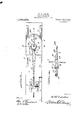
In the accompanyingl drawing` forming a part of this application, Figure 1 isa side elevation of the device. Fig. 2 is a top plan view thereof. Fig'. 3 is a vertical transverse section through the v'same as seen on line to the drawings in which similar reference" characters designate Corresponding` 'parts throughoutthe several views and in which-.
l indicates-a base or platform uponv one end of which is mounted the supportingl standards or the like 2, having` bearings formed at the upper ends thereof, said bearings rotatably receiving therein an axle or shaft carryingthe grooved drive wheel 3, and a crank l carried on the one end of the. shaft oraxle forms a' means whereby the wheel may be readily rotated in the bearings. l
Mounted on the opposite end of the base or platform 1 is -a supporting frame 5 von the upper port-ion of which is carried the tap .groove or opening` 13 tapers .outwardly plate or table 6 and loosely disposed through* this plate or table is a spindle 7, the lower.' end of which isy rotatably supportedon stud or the `like 8 mounted onthebase 41%."60 This4 spindle extending vertically 'through the top 'plate 6, has a pulley 19-1nounted thereon, adjacent its lower end, with; which is engaged a guide belt or the like-.10,'the-i latter also extending over the driVe-yvheelzfg shaped groove or opening .13 extending for a considerableportion of the lengthltll'iereof S0 and leading to a cross bar 1.1 mounted uv the rear end of the tableor top plate. .This
ward its' outer end, thesaine receiving" the through the spindle 'T and removably seA g5 cured Ato the bar 14, on said top plate, is a forwardly projecting` block or the like 15,
which is designed somewhat similar to the groove oropening;` 13. .This projecting block or the like 15 extends for a' portion g() of the length'of said groove 13. and pivotally secured to the outer end thereof through the medium of a vertically' extendmg pintle 1G, are the upper and lower .projecting arms 17 formed on a vibrating block. 95
` 18. This vibrating block 1S is substantially circular in plan and receives therethrough the spindle- T and'in order to keep'the same disposedL in proper position. the lea'` springs 19 are secured to the side faces of the block 15 and projected forwardly to loosely contact v,with the periphery o-fthe block 1S at diametrically oppositeI points thereon.
Pivotally and loosely engaged with the block 1S forward of the spindle 7 is an indicatiiig` needle or the like Q0, said needle being fulcrumed interniedia te of its ends on a stud 21 mounted vertically on the.- topv plate l5. `Said needle is bent somewhatdown Vwardly and offset from the fulnrum point so 110 as to dispose the outer or free end thereof in close proximity to said to) plate. 6 and the Y QL I outer endptv the'to'i plate @.vvhi'ch is convexed at its free e ge, is provided with a ect-ly balanced, the blockjlS Will be caused the needle 20, p In operation, when the spindle 7 is, r0- `tated,`the -lier with the presser thereon Will `also berotated' and if the i-ier is not perscale 22 Which is adapted to `cooperate with to vibrate, therebyvibra-ting the needleQO. The .unbalancing of the hier may be caused by 'the' fact. that the' one arm thereof may be'bent or the presser is to) heavy or too light, and in anyV instance, it can be determined by the indicatingfneedle and'scale.
From the foregoing, it will be seen that I have provided. a device -Which-is extremely simple and durable ,in` construction, inexpensive to manufacture and onel which Willbe very efficient and useful in operation. VWhile I have particularly described the elements best adapted to perform the `functions set forth., it'is obvious that various changes ,in 'form, proportion and in' the minor de.
l tails f construction may be resorted to Withi out departing from A the spirit or sacrificing 'any' of the principles-of the invention.
' Having thus described this invention,
what I claim is z*- f 11. 'A balancing `machine of the class described compr'ising a support, a spindle en tending vertically therethrough,- a member pivo'tally mounted on said support and col o erating with said spindle to vibrate upon t erotation of the' latter, means to yieldingly retain said pivotal member in position on the support, an indicating needle fulcrumed onsaid support and having piv- 4 incedere otal connection with said pivotal member, -a scale -mounted on the support to coperate with said needle, and means to rotate said spindle. v
tending vertically therethrough, a member pivotally'niounted on said support adapted to cooperate with said spindle, spring members engaged With said pivotedmember to normally retain the same in positiongg'xyii ifi indicating needle fulcrunied on said supp and having pivotal connection with said piv- V oted member, a scale formed ony said support 't coperate with said needle, and ni'eans to rotate said spindle.
3. In a balancing machine of the class dei mally dispose the same in position, an indicatingneedle fulcrum'ed onsaid support and having pivotal connection with said block, a scale formed on said table to coperate With said needle, and means to rotate said ,spindle i In testimony whereof I hereunto affix my signature in the `presence of' two Witnesses. v WILLIS WALTER LINDER.l Witnesses: L
It. JENSEN DAWS,
P. l?. GRYDER.
lbalancing machine of the class described coiiiprising. a support, a spindle eX-
Priority Applications (1)
| Application Number | Priority Date | Filing Date | Title |
|---|---|---|---|
| US71004912A US1069272A (en) | 1912-07-17 | 1912-07-17 | Balancing-machine. |
Applications Claiming Priority (1)
| Application Number | Priority Date | Filing Date | Title |
|---|---|---|---|
| US71004912A US1069272A (en) | 1912-07-17 | 1912-07-17 | Balancing-machine. |
Publications (1)
| Publication Number | Publication Date |
|---|---|
| US1069272A true US1069272A (en) | 1913-08-05 |
Family
ID=3137509
Family Applications (1)
| Application Number | Title | Priority Date | Filing Date |
|---|---|---|---|
| US71004912A Expired - Lifetime US1069272A (en) | 1912-07-17 | 1912-07-17 | Balancing-machine. |
Country Status (1)
| Country | Link |
|---|---|
| US (1) | US1069272A (en) |
Cited By (1)
| Publication number | Priority date | Publication date | Assignee | Title |
|---|---|---|---|---|
| US2596762A (en) * | 1950-12-13 | 1952-05-13 | Ideal Machine Shops Inc | Dynamic flyer balancing apparatus |
-
1912
- 1912-07-17 US US71004912A patent/US1069272A/en not_active Expired - Lifetime
Cited By (1)
| Publication number | Priority date | Publication date | Assignee | Title |
|---|---|---|---|---|
| US2596762A (en) * | 1950-12-13 | 1952-05-13 | Ideal Machine Shops Inc | Dynamic flyer balancing apparatus |
Similar Documents
| Publication | Publication Date | Title |
|---|---|---|
| US1069272A (en) | Balancing-machine. | |
| US2205579A (en) | Testing machine | |
| US1252695A (en) | Shaft-balancing machine. | |
| US2065359A (en) | Testing machine for tensile tests | |
| US612978A (en) | Engraving-machine for glass | |
| US1546968A (en) | Machine-aligning apparatus | |
| US1271018A (en) | Connecting-rod jig. | |
| US1363478A (en) | Work-stand | |
| US902497A (en) | Testing-machine. | |
| US1240416A (en) | Testing-machine. | |
| US741911A (en) | Wringer. | |
| US1219914A (en) | Razor-blade sharpener. | |
| US450555A (en) | Tension device for self-binding harvesters | |
| US1186189A (en) | Drum-beater. | |
| GB326651A (en) | Improvements in or relating to machines for testing vehicle tyres | |
| US540324A (en) | luther | |
| US1086699A (en) | Tension-pulley. | |
| US473103A (en) | young | |
| US1003765A (en) | Drafting-machine. | |
| US421271A (en) | Device for testing car-wheels | |
| US1163264A (en) | Speed indicating and controlling device. | |
| US1031034A (en) | Curve-drawing machine. | |
| US246663A (en) | Pantograph | |
| US397700A (en) | William f | |
| US668154A (en) | Phonograph-record duplicator. |