US1069263A - Mantle-shaping machine for inverted mantles. - Google Patents
Mantle-shaping machine for inverted mantles. Download PDFInfo
- Publication number
- US1069263A US1069263A US69039312A US1912690393A US1069263A US 1069263 A US1069263 A US 1069263A US 69039312 A US69039312 A US 69039312A US 1912690393 A US1912690393 A US 1912690393A US 1069263 A US1069263 A US 1069263A
- Authority
- US
- United States
- Prior art keywords
- mantles
- shaft
- machine
- burners
- mantle
- Prior art date
- Legal status (The legal status is an assumption and is not a legal conclusion. Google has not performed a legal analysis and makes no representation as to the accuracy of the status listed.)
- Expired - Lifetime
Links
- 238000007493 shaping process Methods 0.000 title description 5
- 208000025814 Inflammatory myopathy with abundant macrophages Diseases 0.000 description 1
- PSGAAPLEWMOORI-PEINSRQWSA-N medroxyprogesterone acetate Chemical compound C([C@@]12C)CC(=O)C=C1[C@@H](C)C[C@@H]1[C@@H]2CC[C@]2(C)[C@@](OC(C)=O)(C(C)=O)CC[C@H]21 PSGAAPLEWMOORI-PEINSRQWSA-N 0.000 description 1
- 230000001105 regulatory effect Effects 0.000 description 1
- 230000000284 resting effect Effects 0.000 description 1
- 210000001364 upper extremity Anatomy 0.000 description 1
Images


Classifications
-
- F—MECHANICAL ENGINEERING; LIGHTING; HEATING; WEAPONS; BLASTING
- F21—LIGHTING
- F21H—INCANDESCENT MANTLES; OTHER INCANDESCENT BODIES HEATED BY COMBUSTION
- F21H1/00—Incandescent mantles; Selection of imbibition liquids therefor
Definitions
- the object of my invention is to provide a machine of this class, in which a number of mantles may be simultaneously and automatically shaped and burnt, so that an attendant need do nothing more than insert and remove frames containing the mantles. This object is accomplished by my invention, one embodiment of which is hereinafter set forth.
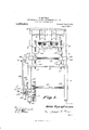
- FIG. 1 is a front elevation of the machine embodying my invention.
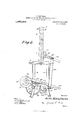
- Fig. 2 is an end elevation of the same.
- Fig. 3 shows details of the automatic and intermittent driving mechanism, the view being a plan view.
- Fig. 4 is an end view of the structure shown in Fig. 3.
- Figs. 5 to 9 inclusive show the sprocket and clutch mechanism, the sprocket being the element that receives power from a suitable source, not shown.
- Figs. 10 to 12 inclusive show details of the stop mechanism.
- My improved machine 1 is provided with suitable legs 2 and a table 3.
- the table 3 carries suitable standards 4 which are united at their upper extremities by means of a suitable gas drum 5, which may be a pipe or any other suitable structure and from this hang suitable pipes 6, the lower ends of which are provided with Bunsen burners 7. Gas is supplied to the drum 5 in any desired way.
- the pipes 6 pass through a suitable brace 8, which also unites the standards 4 and holds these pipes true at all times.
- the standards 4 also contain suitable projections 9 and 10, which are perforated and form guides for rack bars 11.
- the upper ends of these rack bars 11 are united by a suitable frame 12, which carries the inverted mantles 13 and these mantles 13 hang from Specification of Letters Patent.
- the bar 12 is fur ther supported by pins 14 that run upwardly from a shelf 15, which is parallel to the frame 12 and supported by suitable brackets 16 fixed to the rack bars 11. These supports 16 are preferably shaped as shown in Fig. l.
- the rack bars 11 engage segmental gears 17, which are fixed on a horizontally disposed shaft 18, which is mounted in bearings 19 and one end of this shaft 18 is provided with a slotted crank 20 which receives a bolt 21, to which is connected a link 22 that runs in a vertical plane to a second bolt 23 mounted in a slot 24 of a lever 25 on a shaft 26 (for details see Figs.
- the shaft 26 is suitably mounted in a bearing 27, which is a part of a leg 2.
- the shaft 26 also carries a disk 28 with a notch 29, a boss or sleeve 30 and an interrupted gear 31 separated from the bear ing 27 by this sleeve 30.
- the gear 31, the disk 29 and the arm 25 are all fixed to the shaft 26 by means of slots and keys or any other suitable means. As shown in Fig. 12, one wall of the slot 29 is radial.
- the interrupted gear 31 meshes with a corresponding and larger interrupted gear 32 mounted on a suitable shaft 33, the ends of which have bearings 34 in the legs of the machine, the gears being made as shown in Figs. 3 and 4. From these figures, it is obvious that the shafts 26 and 33 will revolve once in the same time or have the same num-, ber of revolutions per minute, so that the shaft 26 will revolve intermittently, while the shaft 33 will revolve continuously and then the shaft 26 will make half its movement in each revolution continuously and then be interrupted in its movement and then make about a quarter of its movement and will finally make tle remainder of its movement.
- the shaft 33 also carries a gear 35, which is fixed thereto and-also to'the interrupted gear 32, so that the gears 32 and 35 will always revolve together.
- the gear 35 is driven by a pinion 36 on a shaft 37 mounted in suitable bearings 38 in a leg 2.
- the shaft. 37 is fixed to a collar 39 provided with a pin 40 running parallel to its axis, as shown in Fig. 5, and surrounding this shaft 37 and resting against the collar 39 is a coiled spring 41, which is adapted to be compressed in a manner which will be described below.
- This spring 41 enters a recess in a sprocket wheel 42, which is mounted on a shaft 37 and normally runs idle thereon. At times, this sprocket wheel, which has pins 43, is forced toward the col hit 39, so that the pin 40 of this collar enga a corresponding pin d3 on the sprocket wheel 42.
- the means by which the sprocketwheel 42 is forced, so that its projections l-I-l engage the projection 4.0 is a crank 44, which is mounted so as to turn freely on the shaft 137 and this crank has a projection 45, that enters a corresponding recess 4L6 in the bearing so that when the crank l-it is moved one way or the other, the projection will ride out of the recess 46 and against the bearing 38, at which time the spring ll compressed and the pin 40 engages a pin 43.
- the sprocket wheel [2 runs continuously and when connected to the collar 39, in the manner above described, this collar will. force the shaft 37 to revolve and the rotation of this shaft will rotate the pinion 36, which is fixed to this shaft and through this pinion the entire apparatus is driven.
- the crank ist is provided with a suitable slot 47, in which is placed a suitable pin i8, and this pin is fixed in a link 49,which is pro vided with a handle 50 at its free end.
- This link 49 is provided with a pin, which engages a spring 51, that runs to a second pin on a leg 2 of the machine.
- This link 49. is also provided with a third pin 53, which is adapted to take into a recess 29 of the disk 28 and when in said recess, this spring 51 holds the pin 53, so that the link l9 causes the crank st-t to be placed in such a position that the projection 4:5 rests in the recess 46 of the bearing 38 and thereby prevents the rotation of the shaft 37.
- the operator grasps the handle 50 and raises the same and allows it to move in the direction of its length under the tension of the spring 51 and until the notch 45 is out of engagement with the recess 16 in the bearing 38.
- the sprocket wheel 42 then drives the shaft 37, as above described, and while the pinion 36 drives the gear 35, wl'iich drives the interrupted gear 32, and this in turn drives the second interrupted gear 31 and through it the shaft 26.
- the interrupted gear 31 is so driven that the mantles are first raised a certain distance and held stationary for a predetermined interval of time and thereafter the mantles are raised still higher or closer to the flame and held stationary another interval of time, after which they are lowered and held stationary another interval of time and finally lowered to the starting position, thus completing the operation.
- the machine then stops automatically because the pin 53 enters the recess 29, thereby forcing the projection 45 into the recess 46, the mantles are removed, a new set are inserted. and the operation is continued as before.
- a fixed frame supporting a plurality of burners
- a movable frame supporting a corresponding number of inverted mantles, racks on said movable frame, gears engaging said racks, and means for moving said gears with an intermittent motion, whereby the mantles are raised and lowered to and from said burners with an intermittent motion step by step.
- a fixed frame a plurality of burners supported by said frame, a movable frame and a plu rality of mantles supported by said movable frame, racks on said movable frame, gears engaging said racks, a shaft mounted in said fixed frame on which said gears are fixed, a crank arm secured to said shaft, a link and means for giving said link an intermittent motion.
- a set of burners removable means for supporting a setof mantles in alinement therewith, means for automatically locking said support against movement and means for unlocking said suppor and moving the mantles toward the burners with a step by step movement.
- a set of burners removable means for supporting a set of mantles in alinement therewith, means for automatically locking said support against movement and means for unlocking said support and moving the mantles toward the burners with a step by step movement and then moving said mantles away from the burners with a step by step movement.
- a set of burners removable means for supporting a set of mantles in alinement therewith, means for moving the mantles toward the burners with a step by step movement, means for moving the mantles away from the burners with a step by step movement, and means for automatically stopping the machine when the mantles reach their limit of movement away from the burners.
- a fixed form supporting a plurality of burners, a movable frame supporting a corresponding number of mantles, means for actuating the movable frame with a step by step movement, a crank, an actuating handle and a limited loose connection between said handle and crank.
- a fixed form supporting a plurality of burn ers, a movable frame supporting a corresponding number of mantles, means for actuating the movable frame with a step by step movement, a crank, an actuating handle, a limited loose connection between said handle and crank and automatic locking means for said handle.
- a fixed form supporting a plurality of burners
- a movable frame supporting a corresponding number of mantles
- means for actuating the movable frame with a step by step movement a crank, an actuating handle, a limited loose connection between said handle and crank and a cooperating locking pin and recess for preventing rotation of the actuating shaft.
- means for supporting a plurality of burners means for supporting a plurality of burners, a movable support for a corresponding number of mantles, means for actuating the latter with a step by step movement and a crank having limited loose connection with its actuating means .whereby the amount of movement of the mantle may be determined.
- means for supporting a plurality of burners means for supporting a plurality of burners, a movable support for a corresponding number of mantles, means for actuating the latter with a step by step movement, a crank having limited loose connection with its actuating means and cooperating means for preventing rotation of the actuating shaft.
Landscapes
- Engineering & Computer Science (AREA)
- General Engineering & Computer Science (AREA)
- Treatment Of Fiber Materials (AREA)
Description
0. KAUFMAN. MANTLE SHAPING MACHINE FOR INVERTED MANTLES.
APPLICATION FILED APR. 12 1912.
1,069,263. Patented Aug. 5, 1913.
5 SHEETSSHEET 1.
Big, 1.
55 gimme/44 301,
5 fa Mm an W qfi COLUMBIA pLANonn/um co wAsmNnTomn. c.
O. KAUFMAN.
MANTLE SHAPING MACHINE FOR. INVERTBD MANTLES.
APPLICATION FILED APR.12, 1912.
1,069,263. Patented Aug. 5, 1913.
5 SHEETSSHEET 2.
awuwwtw i i imam I 0 t a f, a]?
Qtbommg O. KAUFMAN.
MANTLE SHAPING MACHINE FOB. INVEETED MANTLES APPLICATION FILED APRJZ, 1912.
Patented Aug. 5, 1913.
5 SHEBTSSHEET 3.
. Otto Kan man QXM bneoow usumnm PLANDGRAPH co.,wAsmNuToN, n
0. KAUFMAN.
MANTLE SHAPING MACHINE FOB. INVERTED MANTLES.
APPLIOATION FILED APB.12,1912.
1,069,263, Patented Aug. 5, 1913.
5 SHEETS-SHEET 4.
amen tor,
1 W MV/Y' attmug O. KAUFMAN.
MANTLE SHAPING MACHINE FOR INVERTED MANTLES. APPLIOATION FILED APR. 12, 1912.
1,069,263. Patnted Augif), 1913.
5 SHBETSSHEET 5.
m N N N\ g g g N N N M N v ammo a 4 wmmw v I 0660 Ifha 7720172 TTNTTFQD 3TATES PATENT @FFTQE.
OTTO KAUFMAN, OF YOUNGSTOWN, OHIO.
MANTLE-SHAPING MACHINE FOR INVERTED MANTLES.
To all whom it may concern Be it known that I, O'r'ro KAUFMAN, a citizen of the United States, residing in the city of Youngstown, county of Mahoning, and State of Ohio, and whose post-office address is care of the Block Light Co. in said city, have invented a new and useful Improvement in Mantle-Shaping Machines for Inverted Mantles, of which the following is a specification.
The object of my invention is to provide a machine of this class, in which a number of mantles may be simultaneously and automatically shaped and burnt, so that an attendant need do nothing more than insert and remove frames containing the mantles. This object is accomplished by my invention, one embodiment of which is hereinafter set forth.
For a more particular description of my invention, reference is to be had to the accompanying drawings, forming a part hereof, in which- Figure 1 is a front elevation of the machine embodying my invention. Fig. 2 is an end elevation of the same. Fig. 3 shows details of the automatic and intermittent driving mechanism, the view being a plan view. Fig. 4 is an end view of the structure shown in Fig. 3. Figs. 5 to 9 inclusive show the sprocket and clutch mechanism, the sprocket being the element that receives power from a suitable source, not shown. Figs. 10 to 12 inclusive show details of the stop mechanism.
Throughout the various views of the drawings, similar reference characters designate similar parts.
My improved machine 1 is provided with suitable legs 2 and a table 3. The table 3 carries suitable standards 4 which are united at their upper extremities by means of a suitable gas drum 5, which may be a pipe or any other suitable structure and from this hang suitable pipes 6, the lower ends of which are provided with Bunsen burners 7. Gas is supplied to the drum 5 in any desired way. The pipes 6 pass through a suitable brace 8, which also unites the standards 4 and holds these pipes true at all times. The standards 4 also contain suitable projections 9 and 10, which are perforated and form guides for rack bars 11. The upper ends of these rack bars 11 are united by a suitable frame 12, which carries the inverted mantles 13 and these mantles 13 hang from Specification of Letters Patent.
Application filed April 12, 1912.
Patented Aug. 5,1913. Serial n 690,393.
the frame 12 just as they hang when in use and below the burners 7. The bar 12 is fur ther supported by pins 14 that run upwardly from a shelf 15, which is parallel to the frame 12 and supported by suitable brackets 16 fixed to the rack bars 11. These supports 16 are preferably shaped as shown in Fig. l. The rack bars 11 engage segmental gears 17, which are fixed on a horizontally disposed shaft 18, which is mounted in bearings 19 and one end of this shaft 18 is provided with a slotted crank 20 which receives a bolt 21, to which is connected a link 22 that runs in a vertical plane to a second bolt 23 mounted in a slot 24 of a lever 25 on a shaft 26 (for details see Figs. 10 to 12 inclusive) and the shaft 26 is suitably mounted in a bearing 27, which is a part of a leg 2. The shaft 26 also carries a disk 28 with a notch 29, a boss or sleeve 30 and an interrupted gear 31 separated from the bear ing 27 by this sleeve 30. The gear 31, the disk 29 and the arm 25 are all fixed to the shaft 26 by means of slots and keys or any other suitable means. As shown in Fig. 12, one wall of the slot 29 is radial.
The interrupted gear 31 meshes with a corresponding and larger interrupted gear 32 mounted on a suitable shaft 33, the ends of which have bearings 34 in the legs of the machine, the gears being made as shown in Figs. 3 and 4. From these figures, it is obvious that the shafts 26 and 33 will revolve once in the same time or have the same num-, ber of revolutions per minute, so that the shaft 26 will revolve intermittently, while the shaft 33 will revolve continuously and then the shaft 26 will make half its movement in each revolution continuously and then be interrupted in its movement and then make about a quarter of its movement and will finally make tle remainder of its movement. The shaft 33 also carries a gear 35, which is fixed thereto and-also to'the interrupted gear 32, so that the gears 32 and 35 will always revolve together. The gear 35 is driven by a pinion 36 on a shaft 37 mounted in suitable bearings 38 in a leg 2. The shaft. 37 is fixed to a collar 39 provided with a pin 40 running parallel to its axis, as shown in Fig. 5, and surrounding this shaft 37 and resting against the collar 39 is a coiled spring 41, which is adapted to be compressed in a manner which will be described below. This spring 41 enters a recess in a sprocket wheel 42, which is mounted on a shaft 37 and normally runs idle thereon. At times, this sprocket wheel, which has pins 43, is forced toward the col hit 39, so that the pin 40 of this collar enga a corresponding pin d3 on the sprocket wheel 42. The means by which the sprocketwheel 42 is forced, so that its projections l-I-l engage the projection 4.0 is a crank 44, which is mounted so as to turn freely on the shaft 137 and this crank has a projection 45, that enters a corresponding recess 4L6 in the bearing so that when the crank l-it is moved one way or the other, the projection will ride out of the recess 46 and against the bearing 38, at which time the spring ll compressed and the pin 40 engages a pin 43. The sprocket wheel [2 runs continuously and when connected to the collar 39, in the manner above described, this collar will. force the shaft 37 to revolve and the rotation of this shaft will rotate the pinion 36, which is fixed to this shaft and through this pinion the entire apparatus is driven.
The crank ist is provided with a suitable slot 47, in which is placed a suitable pin i8, and this pin is fixed in a link 49,which is pro vided with a handle 50 at its free end. This link 49 is provided with a pin, which engages a spring 51, that runs to a second pin on a leg 2 of the machine. This link 49. is also provided with a third pin 53, which is adapted to take into a recess 29 of the disk 28 and when in said recess, this spring 51 holds the pin 53, so that the link l9 causes the crank st-t to be placed in such a position that the projection 4:5 rests in the recess 46 of the bearing 38 and thereby prevents the rotation of the shaft 37.
In view of the foregoing, the operation of my improved machine will be readily un- ('lGl'SllOOtl.
Assuming the parts to be as shown in Figs. 1 and 2, and the burners all. lighted and ready for use, and the mantles 13 in place, the operator grasps the handle 50 and raises the same and allows it to move in the direction of its length under the tension of the spring 51 and until the notch 45 is out of engagement with the recess 16 in the bearing 38. The sprocket wheel 42 then drives the shaft 37, as above described, and while the pinion 36 drives the gear 35, wl'iich drives the interrupted gear 32, and this in turn drives the second interrupted gear 31 and through it the shaft 26. The interrupted gear 31 is so driven that the mantles are first raised a certain distance and held stationary for a predetermined interval of time and thereafter the mantles are raised still higher or closer to the flame and held stationary another interval of time, after which they are lowered and held stationary another interval of time and finally lowered to the starting position, thus completing the operation. The machine then stops automatically because the pin 53 enters the recess 29, thereby forcing the projection 45 into the recess 46, the mantles are removed, a new set are inserted. and the operation is continued as before.
It is clear that the number of interruptions and their periods will depend on the shapes of the gears 31 and andthcirangit lar velocity and by regulating either of these, any number of stops for any period of time may be provided for. It is im p-ortant that these gears should mesh properly and act as above described, but the pie cise number of stops and the speed at which these gears rotate can be left to the discretion of the operator.
While I have shown and described one embodiment of my lDYGllflClt, it is obvious that it is not restricted thereto, but is broad enough to cover all structures that come within the scope of the annexed claims.
Having thus described my invention, what I claim is 1. In a machine of the class described, a set of burners, removable means for s1 ipporting a set of inverted mantles under said burners, step-by-step means for raising and lowering said mantles with an interrupted motion whereby said mantles will be prop erly burned when the machine is in use and an automatic means for stopping the machine after the mantle has been raised and lowered a predetermined number of times.
2. In a machine of the class described, a fixed frame supporting a plurality of burners, and a movable frame supporting a corresponding number of inverted mantles, racks on said movable frame, gears engaging said racks, and means for moving said gears with an intermittent motion, whereby the mantles are raised and lowered to and from said burners with an intermittent motion step by step.
3. In a machine of the class described, a fixed frame, a plurality of burners supported by said frame, a movable frame and a plu rality of mantles supported by said movable frame, racks on said movable frame, gears engaging said racks, a shaft mounted in said fixed frame on which said gears are fixed, a crank arm secured to said shaft, a link and means for giving said link an intermittent motion.
4. In a machine of the class described, a set of burners, removable means for supporting a setof mantles in alinement therewith, means for automatically locking said support against movement and means for unlocking said suppor and moving the mantles toward the burners with a step by step movement.
5. In a machine of the class described, a set of burners, removable means for supporting a set of mantles in alinement therewith, means for automatically locking said support against movement and means for unlocking said support and moving the mantles toward the burners with a step by step movement and then moving said mantles away from the burners with a step by step movement.
6. In a machine of the class described, a set of burners, removable means for supporting a set of mantles in alinement therewith, means for moving the mantles toward the burners with a step by step movement, means for moving the mantles away from the burners with a step by step movement, and means for automatically stopping the machine when the mantles reach their limit of movement away from the burners.
7. In a machine of the class described, a fixed form supporting a plurality of burners, a movable frame supporting a corresponding number of mantles, means for actuating the movable frame with a step by step movement, a crank, an actuating handle and a limited loose connection between said handle and crank.
8. In a machine of the class described, a fixed form supporting a plurality of burn ers, a movable frame supporting a corresponding number of mantles, means for actuating the movable frame with a step by step movement, a crank, an actuating handle, a limited loose connection between said handle and crank and automatic locking means for said handle.
9. In a machine of the class described, a fixed form supporting a plurality of burners, a movable frame supporting a corresponding number of mantles, means for actuating the movable frame with a step by step movement, a crank, an actuating handle, a limited loose connection between said handle and crank and a cooperating locking pin and recess for preventing rotation of the actuating shaft.
10. In a machine of the class described, means for supporting a plurality of burners, a movable support for a corresponding number of mantles, means for actuating the latter with a step by step movement and a crank having limited loose connection with its actuating means .whereby the amount of movement of the mantle may be determined.
11. In a machine of the class described, means for supporting a plurality of burners, a movable support for a corresponding number of mantles, means for actuating the latter with a step by step movement, a crank having limited loose connection with its actuating means and cooperating means for preventing rotation of the actuating shaft.
Signed at the city of Youngstown, county of Mahoning, and State of Ohio, this 10th day of April, 1912.
OTTO KAUFMAN. Witnesses:
J os. PHILLIPS, CHARLES KIRsGH.
Copies of this patent may be obtained for five cents each, by addressing the Commissioner of Patents, Washington, D. C.
Priority Applications (1)
| Application Number | Priority Date | Filing Date | Title |
|---|---|---|---|
| US69039312A US1069263A (en) | 1912-04-12 | 1912-04-12 | Mantle-shaping machine for inverted mantles. |
Applications Claiming Priority (1)
| Application Number | Priority Date | Filing Date | Title |
|---|---|---|---|
| US69039312A US1069263A (en) | 1912-04-12 | 1912-04-12 | Mantle-shaping machine for inverted mantles. |
Publications (1)
| Publication Number | Publication Date |
|---|---|
| US1069263A true US1069263A (en) | 1913-08-05 |
Family
ID=3137500
Family Applications (1)
| Application Number | Title | Priority Date | Filing Date |
|---|---|---|---|
| US69039312A Expired - Lifetime US1069263A (en) | 1912-04-12 | 1912-04-12 | Mantle-shaping machine for inverted mantles. |
Country Status (1)
| Country | Link |
|---|---|
| US (1) | US1069263A (en) |
-
1912
- 1912-04-12 US US69039312A patent/US1069263A/en not_active Expired - Lifetime
Similar Documents
| Publication | Publication Date | Title |
|---|---|---|
| US1069263A (en) | Mantle-shaping machine for inverted mantles. | |
| US804170A (en) | Bottle-washing machine. | |
| US1069262A (en) | Mantle-shaping machine for upright mantles. | |
| US610781A (en) | Oooooooooooooooooooo | |
| US713621A (en) | Dipping ceramic glass, &c. | |
| US1241145A (en) | Crimping-machine. | |
| US1187864A (en) | Apparatus for changing the positions of hanks of yarn on dyeing-sticks. | |
| US1043672A (en) | Fabric-singeing machine. | |
| US689067A (en) | Candy-machine. | |
| US851253A (en) | Fuel-feeding device for boiler-furnaces. | |
| US914225A (en) | Hose-making machine. | |
| US1015998A (en) | Dipping-machine. | |
| US998257A (en) | Polishing apparatus. | |
| US1009413A (en) | Cake-centering device for depositing-machines. | |
| US1100785A (en) | Advertising-machine. | |
| US563330A (en) | smith | |
| US465842A (en) | Machine | |
| US1227545A (en) | Clutch-timing mechanism. | |
| US1213048A (en) | Washing-machine. | |
| US787285A (en) | Skein-dyeing machine. | |
| US671546A (en) | Machine for using side seams of metal cans, & c. | |
| US1179396A (en) | Oven-grate. | |
| US685351A (en) | Bottle-washing machine. | |
| US1615345A (en) | Ice-cream-cone-making machine | |
| US221438A (en) | Improvement in machines for flanging metal plates |