US1069231A - Baling-press. - Google Patents
Baling-press. Download PDFInfo
- Publication number
- US1069231A US1069231A US74985113A US1913749851A US1069231A US 1069231 A US1069231 A US 1069231A US 74985113 A US74985113 A US 74985113A US 1913749851 A US1913749851 A US 1913749851A US 1069231 A US1069231 A US 1069231A
- Authority
- US
- United States
- Prior art keywords
- baling
- plunger
- pinion
- head block
- feeder
- Prior art date
- Legal status (The legal status is an assumption and is not a legal conclusion. Google has not performed a legal analysis and makes no representation as to the accuracy of the status listed.)
- Expired - Lifetime
Links
Images


Classifications
-
- B—PERFORMING OPERATIONS; TRANSPORTING
- B30—PRESSES
- B30B—PRESSES IN GENERAL
- B30B9/00—Presses specially adapted for particular purposes
- B30B9/30—Presses specially adapted for particular purposes for baling; Compression boxes therefor
- B30B9/306—Mechanically-driven presses
- B30B9/3067—Mechanically-driven presses by rack-and-pinion means
Definitions
- This invention relates to baling presses and has for its object to produce a machine of this character having a longer stroke and capable of exerting greater power in such stroke than machines of the same general character and length.
- Another object is to produce a baling press provided with mechanism whereby the maximum power which could be applied directly by the pitman on the baling material is increased on the latter at a loss of speed on the part of the plunger or head block.
- Another object is to produce a baling press having an automatically operating feeder and means whereby the power of the operative stroke of the feeder is increased as the resistance offered to the feeder by the baling material is increased by the compact ing or condensing of the latter in the baling chamber.
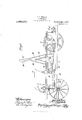
- Figure 1 is a side elevation of a part of a baling press embodying my invention.
- Fig. 2. is an enlarged central vertical longitudinal section of a part of the press.
- Fig. 8 is a section on the line IIIIII of Fig. 2.
- Fig. is a section on the line IV-IV of Fig. 2 with part of the crank shaft mecha nism in elevation.
- Fig. 5 is a central vertical longitudinal section of a part of a press embodying certain changes of construction from the press shown in the preceding figures.
- Fig. 1 is a side elevation of a part of a baling press embodying my invention.
- Fig. 2. is an enlarged central vertical longitudinal section of a part of the press.
- Fig. 8 is a section on the line IIIIII of Fig. 2.
- Fig. is a section on the line IV-IV of Fig. 2 with part of the crank shaft mecha nism in elevation.
- Fig. 5 is a central vertical longitudinal section of a part of
- Fig. 6 is a similar view but with the plunger at the beginning instead of at the end of its stroke as in Fig. 5.
- Fig. 7 is a vertical transverse section on the line VII-VII of Fig. 6.
- Fig. 8, is a detail perspective view of one member of the pinion segment shown on Sheets 4 to 6 inclusive.
- the frame 1 of the press is of the customary construction as shown and 2 incli- Specification of Letters Patent.
- a shaft adapted to be driven by an engine or belt and provided with a pair of pinions 5meshing with the large gear wheels 6 journal-ed in the frame of the machine and connected together by a cross pin 7 which pin in conjunction with the wheels 6 constitute a crank connected pivotally by a pitman 8 with agear toothed pinion 9, the connect-ion being out-ward of the center of the pinion for a purpose which hereinafter appears, and said pinion engages a rack bar 10 extending longitudinally of and rigid with the frame.
- the apron 11 of the head block or plunger operates above said rack bar and between the sides of the frame, as shown clearly in Fig. 2.
- a rack bar 12 adapted to travel longitudinally upon the bottom of the baling case and mounted at its rear end upon a pair of rollers 13 and pivotally connected at its front end to the head block or plunger by a pin 14.
- 2a is a clamp plate bridging the space between levers 21 and resting upon the upper edges of the same, and is aspring for causing said plate 24 to hold the levers 21 pressed yieldingly against the sleeve 17 the spring being held in position by means of a bolt 26, which extends through plate 25 and a similar plate 27 bridging the space between and hearing at its end upwardly against arms 18, a washer and a nut 29 fitting on the upper end of the bolt and holding the spring under tension.
- the head block of the plunger is also provided with extension sides 39 fitting against the inner side of the baling chamber and provided with short longitudinal slots 4:0 wherein travel flanged rollers ll journaled upon the shaft 32 and forming a means to guard against tilting of the head block of the plunger.
- the pitman S pivotally connected at one end to crank 7, is pivotally connected at 42 to the pinion segment, and the latter is also pivotally connected at 1:3 by a link ist with the head block or plunger at to, itbeing noted that radial planes intersecting the axis of the pinion segment from pivots t2 and extend at an angle to each other.
- the feeder mechanism for forcing baling material from the hopper into the baling chamber in advance of the head block or plunger corresponds substantially to that shown in Sheets 1 to 3 inclusive. its in the former sheets, 15 indicates the standards extending upward from the baling case and 16 the transverse shaft ournaled in said standards. 16 is a casting journaled on said shaft and provided with a pair of arms l? pivotally connected at as to a link 19 pivotally connected to the pinion segment 31 at as distinguished from the links 20 which are pivotally connected to the reciprocatory rack bar 12.
- levers 21 are levers pivotally connected at 128 to arms 17 and also connected to the presser foot 22 as in Sheets 1 to 3 inelusive, and said levers 21 are held pressed flatly against the casting 16 by clamp plate 24; through the instrumentality of a spring 25, a rod 26 extending through said plate 2% and casting 16 and said spring and a washer 28 and nut 29 engaging the upper end of the spring and rod respectively, and to maintain the presser foot in substantially vertical position it is pivotally connected as hereinbefore explained to the standards 15 by the links 30.
- Sheets 4 to 6 inclusive provides for more powerful compression at the extreme end of the advance stroke of the plunger and thus produces more compact bale, and owing to the connection of the feeder with the pinion segment instead of with the head block or plunger, the leverage on the feeder is increased at the time when power is most required, namely at the moment the feeder enters the baling case, when it is desirable that the baling material shall be condensed to the greatest extent as by giving the feeder additional power at such time, larger charges of baling material may be introduced within the hopper and the entire operation of baling be thereby facilitated.
- crank 7 pivot 42, pivot 43 and pivot 45 are alined, and at that moment the pressure of the head block or plunger on the baling material is equal to that imposed by the crank on the pitman. Under the remainder of the second half revolution of the crank, the parts move from the position shown in dotted lines Fig. 6, to the position shown in full lines Fig.
- a baling case a reciprocatory head block therein, a fixed part, a lever having a rolling fulcrum engagement with said bar, a pitman pivotally con nected to said lever to cause the same to roll along said part in opposite directions alteret- 1,oes,2s1
- a haling press a baling ass, a reciprocatory head-block thercm, a fixed rack bar extending liiiiigitndinalljv' oi? the press, a toothed lever to trawl along and constantly tulcrunr on iillil rack-liar, a pitinan to eitlect adrani're and retrograde trai'cl of said over, and means act art it by the rolling adv nee or retiogra le increment of the lever for n11- parting adwance or Withdrawal movement to the head block,
- balin ciprecatory iead block in a baling press, a balin ciprecatory iead block, a 1 nally extending g bar, a lever to roll. aon and constantly change its l: ilcruni point on said bar, a pitinan to eiiiecl; advance and r f 'n UI C 1 l 1!]1 41" f l 1 llllilfluo time or Win. we an a in. p
- a haling case In a baling press, a haling case, a reirin oi? with said rack bar, a link pivotally connectin said.
- pinion segment with the head-block, a pitinan pivotally connected at its front end with said pinion segment, a pivoted feeder for operating in a verticil plane, and a link pivotally connecting the feeder With said pinion segment.
- a baling case a baling case, a driven crank shaft, a fined rack bar extending longitudinally of the case, a reciprocatory head block in the case, pinion segment interineshed with the rack var, a pitinan pivotally connecting the (tank shaft "with the pinion segment, a link pivotally connecting the i inion segment with the head bio l1, and means for retaining the pinion 'nent in mesh with the rack bar Without interfering with its tr: Ye thereon.
- a baling ease having longigiulinal slots in its side Walls, a fixed liCli bar extending longitudinally of the cas'i and :lfacing downi'vard, a pinion segment engaging the rack bar and having a shaft projecting through the said slots, rollers mounted on said shaft, upper and lower cl; 1: at opposite sides of and ch nged by said rollers to retain the pinion sonnentin engagement with the 210k bar Without interfering with the travel thereof, a reciprecatory head block in the case, means to impart rolling travel to the pinion on the bar, and a link pivotally connecting V 'on segment with the head block.
- a baling case having longitudinal slots in its sire Walls, a fixed rael: bar extending longitudinally of the case and facing downward, a plnlon segment engaging the rack bar and having a shaft projecting through the said slots, rollers n o l (11 said shaft, upper and 1 track bars ,1 opgosite sides of and enlers to retain the pinion G.
- rollers n o l 11 said shaft, upper and 1 track bars ,1 opgosite sides of and enlers to retain the pinion G.
Description
C. L. COOKSON.
BALING PRESS.
APPLICATION FILED FEB. 21, 1913.
Patented Aug. 5, 1913.
6 SHEETS-SHEET 1.
C. L. OOOKSON.
BALING PRESS.
APPLICATION 111mm FEB. 21, 1913.
1,069,231, Patented Aug.5, 1913.
6 SHEETS-SHEET 2.
11E I BYL %'iiwtmw 50216??? 6.15.6 00 07 zzfifi W M FLAND'GRAPH CD-.WASHINUTON D c C. L. GOOKSON.
BALING PRESS.
APPLICATION FILED FEB. 21. 191% 1,069,231 Patented Aug. 5, 1913.
6 SHEETSSHEET 3. Q g
5 Q Q E s M @5 6L5. bokaovc I MW m PLANOGRAPH C0..wAsH|NGTO G. L. OOOKSON.
BALING PRESS. V
APPLIcATIpN FILED FEB. 21, 1913.
1,069,231 Patented Aug. 5, 1913.
6 SHEETSSHEET 4v 22%;??? N \1 Q Can/5 21c .G. L. GOOKSON.
BALING PRESS.
APPLICATION FILED 313.21, 1913 1,069,231 v Patented Aug.5, 1913.
6 SHEETS-SHEET 5.
COLUMBIA PLANOGRAPH 110., WASHINGTON. D, c,
C. L. COOKSON.
BALING PRESS.
APPLICATION FILED FEB. 21, 1913.
Patented Aug. 5, 191 3.
6 'SHBETS-SHEET 6.
w A w a W TATES PATENT OFFIQE.
CHARLES L. COOKSON, OF KANSAS CITY, MISSOURI, ASSIGNOR TO ADMIRAL HAY PRESS COMPANY, OF KANSAS CITY, MISSOURI, A CORPORATION OF MISSOURI.
BALING-PRESS.
T (ZZZ whom it may concern:
Be it known that 1, CHARLES L. CooitsoN, a citizen of the United States, residing at Kansas City, in the county of Jackson and State of Missouri, have invented certain new and useful Improvements in Baling- Presses, of which the following is a specification.
This invention relates to baling presses and has for its object to produce a machine of this character having a longer stroke and capable of exerting greater power in such stroke than machines of the same general character and length.
Another object is to produce a baling press provided with mechanism whereby the maximum power which could be applied directly by the pitman on the baling material is increased on the latter at a loss of speed on the part of the plunger or head block.
Another object is to produce a baling press having an automatically operating feeder and means whereby the power of the operative stroke of the feeder is increased as the resistance offered to the feeder by the baling material is increased by the compact ing or condensing of the latter in the baling chamber.
With these general objects in view the invention consists in certain novel and peculiar features of construction and organization as hereinafter described and in order that it may be fully understood reference is to be had to the accompanying drawings, in which Figure 1, is a side elevation of a part of a baling press embodying my invention. Fig. 2. is an enlarged central vertical longitudinal section of a part of the press. Fig. 8, is a section on the line IIIIII of Fig. 2. Fig. is a section on the line IV-IV of Fig. 2 with part of the crank shaft mecha nism in elevation. Fig. 5, is a central vertical longitudinal section of a part of a press embodying certain changes of construction from the press shown in the preceding figures. Fig. 6, is a similar view but with the plunger at the beginning instead of at the end of its stroke as in Fig. 5. Fig. 7, is a vertical transverse section on the line VII-VII of Fig. 6. Fig. 8, is a detail perspective view of one member of the pinion segment shown on Sheets 4 to 6 inclusive.
The frame 1 of the press is of the customary construction as shown and 2 incli- Specification of Letters Patent.
Application filed February 21, 1913.
Patented Aug. 5,1913. Serial No. 749,851.
cates the usual hopper and 3 the reciprocatory head block or plunger.
4 is a shaft adapted to be driven by an engine or belt and provided with a pair of pinions 5meshing with the large gear wheels 6 journal-ed in the frame of the machine and connected together by a cross pin 7 which pin in conjunction with the wheels 6 constitute a crank connected pivotally by a pitman 8 with agear toothed pinion 9, the connect-ion being out-ward of the center of the pinion for a purpose which hereinafter appears, and said pinion engages a rack bar 10 extending longitudinally of and rigid with the frame. In Figs. 1 to 1 inclusive, the apron 11 of the head block or plunger operates above said rack bar and between the sides of the frame, as shown clearly in Fig. 2.
Underlying and engaging the pinion 9 is a rack bar 12 adapted to travel longitudinally upon the bottom of the baling case and mounted at its rear end upon a pair of rollers 13 and pivotally connected at its front end to the head block or plunger by a pin 14.
15 are standards mounted upon the frame and forming a support and journal for a transverse shaft 16, and mounted pivotally upon said shaft between the ends of the spacing sleeve 17 thereon and said standards 15, is a pair of swing arms 18, connected at their outer ends by a cross pin 19.
20 is a pair of links pivotally connecting cross pin 19 with rack bar 12, at opposite sides of the pinion 9 for the purpose of imparting rocking movement to arms 18 and a pair of levers 21 which are pivoted on cross pin 19, and rest on sleeve 17 and pivotally carry at their front ends a presser foot 22 for forcing baling material from the hopper into the baling chamber, the upper end of the hopper being notched at 23 to accommodate the levers 21.
2a is a clamp plate bridging the space between levers 21 and resting upon the upper edges of the same, and is aspring for causing said plate 24 to hold the levers 21 pressed yieldingly against the sleeve 17 the spring being held in position by means of a bolt 26, which extends through plate 25 and a similar plate 27 bridging the space between and hearing at its end upwardly against arms 18, a washer and a nut 29 fitting on the upper end of the bolt and holding the spring under tension.
To maintain the presser foot in a substantially vertical position throughout its entire travel in feeding hay from the hopper into the baling chamber and in withdrawing to position above the hopper, I provide apair of links which pivotally connect the upper end of the presser foot with the upper ends of the standards 15.
In Sheets 1-, 5 and 6, parts identical in construction and function with parts of Sheets 1 to 3 inclusive, are correspondingly numbered. In said Sheets 4: to 6 inclusive, 1 use a pinion segment 31 in place of the gear pinion and axially of the said segment it is provided with a transverse shaft 32 which extends thrcugh longitudinal slots 33 in the side walls of the baling case and is equipped at its ends with rollers 34 traveling upon and between pairs of spaced tracks and 36 secured externally to the baling case, it being noted in this connection that the pinion mentconsists of two members correspondingly numbered and that there is a pair of fixed overlying rack bars 37 cast or otherwise rigidly formed with the bridge plate 38 mounted on the sides of the frame and forming a substitute for the single rack bar 10 of Sheets 1 to 3 inclusive. In Sheets 4 to 6 inclusive, the head block of the plunger is also provided with extension sides 39 fitting against the inner side of the baling chamber and provided with short longitudinal slots 4:0 wherein travel flanged rollers ll journaled upon the shaft 32 and forming a means to guard against tilting of the head block of the plunger. The pitman S pivotally connected at one end to crank 7, is pivotally connected at 42 to the pinion segment, and the latter is also pivotally connected at 1:3 by a link ist with the head block or plunger at to, itbeing noted that radial planes intersecting the axis of the pinion segment from pivots t2 and extend at an angle to each other. The feeder mechanism for forcing baling material from the hopper into the baling chamber in advance of the head block or plunger corresponds substantially to that shown in Sheets 1 to 3 inclusive. its in the former sheets, 15 indicates the standards extending upward from the baling case and 16 the transverse shaft ournaled in said standards. 16 is a casting journaled on said shaft and provided with a pair of arms l? pivotally connected at as to a link 19 pivotally connected to the pinion segment 31 at as distinguished from the links 20 which are pivotally connected to the reciprocatory rack bar 12. 21 are levers pivotally connected at 128 to arms 17 and also connected to the presser foot 22 as in Sheets 1 to 3 inelusive, and said levers 21 are held pressed flatly against the casting 16 by clamp plate 24; through the instrumentality of a spring 25, a rod 26 extending through said plate 2% and casting 16 and said spring and a washer 28 and nut 29 engaging the upper end of the spring and rod respectively, and to maintain the presser foot in substantially vertical position it is pivotally connected as hereinbefore explained to the standards 15 by the links 30.
Referring first to the operation. of the construction shown in Sheets 1 to inclusive, and assuming that the feeder is elevated, the head block or plunger is advanced, and the crank is being turned in the direction indicated by the arrow Fig. 1, it will be seen that the pitman is about to startin the direction indicated by the adjacent arrow, and hence utilize the pinion 9 as a lever fulcrumed. at its upper side on rack bar 10, to effect withdrawing movement of rack bar 12 and the head block or plunger and down ward movement of the feeder. The initial. part of the withdrawal mov ment of the head block or plunger is relatively slow but increases rapidly owing to the fact that the leverage decreases as the pivotal point of connection between the pitman and 'he pinion gradually approaches nearer to the fulcrum point, that is to say moves convergingly upward with respect to the end of the rack bar remote from the hopper, and in this connection it will be apparent that owing to the gradual increase in speed of the with drawal movement of the plunger, the downward movement of the feeder likewise becomes more rapid and hence more eifective in overcoming resistance of the baling material, as the latter becomes closely bunched in the baling chamber, as will be readily under-- stood by reference to Fig. 2, which figure also shows that the head block or plunger has nearly completed its withdrawal stroke before the lower end of the feeder passes from the hopper into the baling chamber, and for this reason there is no chance of conflict between the head block or plunger and the feeder. At the end of a half revolution of the crank, the latter in the position shown in Fig. 2, so that as its rotation continues, the initial advance movement of the head block or plunger and upward move ment of the feeder is very rapid owing to the long leverage which the pinion 9, has on the rack bar 12. This rapid preliminary move ment of the head block or plunger is desirable because it occurs when the baling mate rial is loose and offers but little resistance and when the least power or force is required. As the head block or plunger is advanced the leverage thereon is diminished by diverging movement of the pivotal point of connection of the pitman with the pinion from the said remote end of the rack bar 10, and as the first revolution of the crank is completed the advance movement of the head block or plunger is slow but powerful, owing to the fact that the pivotal point of connection between the pitman and the pinion 9 is very close to the point where said pinion applies its power on the rack bar 12. It will be obvious that the upward movement of the feeder diminishes in speed as the advance of the plunger slows down, owing to the factthat the said elements are linked together.
Referring now to Sheets 4 to 6 inclusive, in which the crank of course operates in the same direction as in Sheets 1 to 3 inclusive, it is desired to call attention to two features of construction which in principle are be lieved to be the same as in Sheets 1 to 3 inclusive but which are believed to possess advantages not possessed by the latter type of construction. The construction shown by Sheets 4 to 6 inclusive provides for more powerful compression at the extreme end of the advance stroke of the plunger and thus produces more compact bale, and owing to the connection of the feeder with the pinion segment instead of with the head block or plunger, the leverage on the feeder is increased at the time when power is most required, namely at the moment the feeder enters the baling case, when it is desirable that the baling material shall be condensed to the greatest extent as by giving the feeder additional power at such time, larger charges of baling material may be introduced within the hopper and the entire operation of baling be thereby facilitated.
Referring now in detail to the operation of the construction shown by Sheets 4 to 6 inclusive, it will be seen that as the crank moves downward from the horizontal position shown in Fig. 5, it exerts a pull on the pinion segment 31 whereby the latter swings on the rack bars 37 as a fulcrum, and begins to withdraw the head block or plunger, through the instrumentality of the link 44, and the feeder is caused to descend through the connections between the same and the segment, continued movement of the pitman resulting in its pivot 42 traveling diagonally upward toward the end of the rack bars remote from the hopper, and thereby diminishing the leverage on the crank of the segment and effecting an'increase in the speed of withdrawal movement of the head block or plunger and the descending movement of the feeder. It will be noticed, however, that owing to the fact that the pivotal point 50 moves continually nearer to the fulcrum or rack bar on which the segment travels, the leverage on the feeder is increased and its speed of downward movement is proportionately diminished so that its maximum power is available for efiecting the greatest possible condensation of the baling material in the baling chamber in advance of the head block or plunger. As the rotation of the crank continues from the position shown in Fig. 6, the pinion segment swings under the pressure of pitman 8 and imparts rapid advance movement to the head block or plunger and upward movement to the feeder, the movement of the latter being relatively slow but sufficiently rapid to avoid conflict with the advancing head block or plunger. When the plunger has made something more than half of its advance stroke, the crank 7 pivot 42, pivot 43 and pivot 45 are alined, and at that moment the pressure of the head block or plunger on the baling material is equal to that imposed by the crank on the pitman. Under the remainder of the second half revolution of the crank, the parts move from the position shown in dotted lines Fig. 6, to the position shown in full lines Fig. 5, in which latter position it will be noticed that pivot 43 is above the plane occupied by pivots 7 and 42 and the inclined plane occupied by pivots 42 and 45, and that this final movement of the head block or plunger oc curs with the maximum power developed by the machine, that is with a greater power than that which is imposed by the crank when the four pivots mentioned are alined as shown in dotted lines Fig. 6, it being understood that this extra or excess power is of course obtained by a decrease in the speed of the advance movement of the plunger. It will be understood that the segment when it has attained the position shown by dotted lines Fig. 6constitutes one member of a toggle of which the link 44 constitutes the other member, and that after the parts have attained the position mentioned, the crank 7 utilizes the segment as a long lever fulcrumed on the rack-bar tooth nearest the head-block or plunger, for expanding said toggle and thereby efiecting advance moveaent of the hea d-block or plunger from the said dotted position to the position shown in Fig. 5. By thus straightening or expanding the toggle after the application of direct power by the crank upon the head block or plunger ceases, as when the parts are in the position shown by dotted lines Fig. 6, a compound leverage is obtained whereby the baling material is compressed to greater density than is possible by any direct application of power from the crank.
From the above description it will be apparent that I have produced a baling press embodying the features of advantage enumerated as desirable and 1 wish it to be understood that while 1 have illustrated and described the preferred embodiment of the invention I reserve the right to make all changes falling within the spirit and scope of the appended claims.
1 claim 1. In a baling press, a baling case. a reciprocatory head block therein, a fixed part, a lever having a rolling fulcrum engagement with said bar, a pitman pivotally con nected to said lever to cause the same to roll along said part in opposite directions alteret- 1,oes,2s1
nately, and means actuated by the increment oi said lever for imparting the power stress and r-ritluglra val stroke to the head-block.
2. ln a haling press, a baling ass, a reciprocatory head-block thercm, a fixed rack bar extending liiiiigitndinalljv' oi? the press, a toothed lever to trawl along and constantly tulcrunr on iillil rack-liar, a pitinan to eitlect adrani're and retrograde trai'cl of said over, and means act art it by the rolling adv nee or retiogra le increment of the lever for n11- parting adwance or Withdrawal movement to the head block,
in a baling press, a balin ciprecatory iead block, a 1 nally extending g bar, a lever to roll. aon and constantly change its l: ilcruni point on said bar, a pitinan to eiiiecl; advance and r f 'n UI C 1 l 1!]1 41" f l 1 llllilfluo time or Win. we an a in. p
Y r." .4 1 Z -i (Lill connecting said ieiei min rho heroblock and 01' ring with the lever, a toggle between the road block and a point along the length of paid bar.
t. in a haling press. a haling case, a reciproeatory head block, a fixed longitudinally extenilr bar, a l.'-3\\,i to roll along and eonstai tl clange its '5' ilcrun'i point on said bar, a pitin "an to eiieei adva .co and retrograde trai cl of said lever, a link pivot ally connecting said lever with the l block and hauling with the lover, a toggle between the head block and a point along the length or said bar, a pivoted feeder to force bailing material into the bailing chamher, and con motions between said lever and said feeder ior eilt'ecting upward more ntot the latter, as the he; =-l'iloclr is advanced and downiu'ard increment of iccder as L11 the head lilocl: is withdrawn balinr; a hali i ciprocaiony heao bloen, a lllicil lo nally extending bar, a lever to roll aim g cadl. i a
constantl cl'iange its tnlcruin point or bar, a pitinan to diet; adrance and grade travel oi? d lover. a link piioizi COZ13 GCil1 ni(l lbt' mining the lover, a between the head block and a point ale 116 length oi said bar, a pivoted .ii'eeder, a a lii l. pivoaally connect Mr the resale th said lever that the le rage of the lever on the feeder shall diminish as the feeder i upa Ward and shall increase as the ecder makes its op osite or power strikev 6- Zn a liialing p a baling c rocatory head hloclc illCl tending li'nigicndinally of the c in the form of a pinion se "with said. rack l ar, a link pivotally ing said pinion se ment with said head hloelr, and a pitinan piicctally connected at its front end \Ylill said pinion segmen i. In a baling press, a haling case, a reirin oi? with said rack bar, a link pivotally connectin said. pinion segment with the head-block, a pitinan pivotally connected at its front end with said pinion segment, a pivoted feeder for operating in a verticil plane, and a link pivotally connecting the feeder With said pinion segment.
8. In a baling press, a baling case, a driven crank shaft, a fined rack bar extending longitudinally of the case, a reciprocatory head block in the case, pinion segment interineshed with the rack var, a pitinan pivotally connecting the (tank shaft "with the pinion segment, a link pivotally connecting the i inion segment with the head bio l1, and means for retaining the pinion 'nent in mesh with the rack bar Without interfering with its tr: Ye thereon.
9. in a baling press, a baling ease having longigiulinal slots in its side Walls, a fixed liCli bar extending longitudinally of the cas'i and :lfacing downi'vard, a pinion segment engaging the rack bar and having a shaft projecting through the said slots, rollers mounted on said shaft, upper and lower cl; 1: at opposite sides of and ch nged by said rollers to retain the pinion sonnentin engagement with the 210k bar Without interfering with the travel thereof, a reciprecatory head block in the case, means to impart rolling travel to the pinion on the bar, and a link pivotally connecting V 'on segment with the head block.
110, in a haling press, a baling case having longitudinal slots in its sire Walls, a fixed rael: bar extending longitudinally of the case and facing downward, a plnlon segment engaging the rack bar and having a shaft projecting through the said slots, rollers n o l (11 said shaft, upper and 1 track bars ,1 opgosite sides of and enlers to retain the pinion G. Y. Ti-ionrn.
Copies of this patent may be obtained for five cents each, by addressing the Commissioner of Itatents. Washington, 13. U.
Priority Applications (1)
| Application Number | Priority Date | Filing Date | Title |
|---|---|---|---|
| US74985113A US1069231A (en) | 1913-02-21 | 1913-02-21 | Baling-press. |
Applications Claiming Priority (1)
| Application Number | Priority Date | Filing Date | Title |
|---|---|---|---|
| US74985113A US1069231A (en) | 1913-02-21 | 1913-02-21 | Baling-press. |
Publications (1)
| Publication Number | Publication Date |
|---|---|
| US1069231A true US1069231A (en) | 1913-08-05 |
Family
ID=3137468
Family Applications (1)
| Application Number | Title | Priority Date | Filing Date |
|---|---|---|---|
| US74985113A Expired - Lifetime US1069231A (en) | 1913-02-21 | 1913-02-21 | Baling-press. |
Country Status (1)
| Country | Link |
|---|---|
| US (1) | US1069231A (en) |
-
1913
- 1913-02-21 US US74985113A patent/US1069231A/en not_active Expired - Lifetime
Similar Documents
| Publication | Publication Date | Title |
|---|---|---|
| US1069231A (en) | Baling-press. | |
| US682514A (en) | Baling-press. | |
| US650494A (en) | Baling-press. | |
| US536765A (en) | Baljng-press | |
| US29874A (en) | Improvement in cotton-presses | |
| US1248753A (en) | Hay-press. | |
| US2286486A (en) | Power mechanism for hay balers | |
| US659799A (en) | Baling-press. | |
| US216785A (en) | Improvement in hay-presses | |
| US550598A (en) | Baling-press | |
| US372636A (en) | Baling-press | |
| US457369A (en) | Baling-press | |
| US561265A (en) | Press | |
| US526441A (en) | Hay-press | |
| US1333067A (en) | brandt | |
| US354304A (en) | Minoe s | |
| US837540A (en) | Baling-press. | |
| US772929A (en) | Baling-press. | |
| US715409A (en) | Baling-press. | |
| US1401715A (en) | Hay-press | |
| US827956A (en) | Hay-press. | |
| US1082454A (en) | Lever mechanism for baling-presses. | |
| US1073304A (en) | Hay-press. | |
| US575660A (en) | Baling-press | |
| US806808A (en) | Baling-press. |