US10692282B2 - Modeling apparatus and modeling method - Google Patents
Modeling apparatus and modeling method Download PDFInfo
- Publication number
- US10692282B2 US10692282B2 US16/507,038 US201916507038A US10692282B2 US 10692282 B2 US10692282 B2 US 10692282B2 US 201916507038 A US201916507038 A US 201916507038A US 10692282 B2 US10692282 B2 US 10692282B2
- Authority
- US
- United States
- Prior art keywords
- edge
- nodes
- edges
- node
- evaluation value
- Prior art date
- Legal status (The legal status is an assumption and is not a legal conclusion. Google has not performed a legal analysis and makes no representation as to the accuracy of the status listed.)
- Active
Links
Images


Classifications
-
- G—PHYSICS
- G06—COMPUTING OR CALCULATING; COUNTING
- G06T—IMAGE DATA PROCESSING OR GENERATION, IN GENERAL
- G06T17/00—Three-dimensional [3D] modelling for computer graphics
- G06T17/20—Finite element generation, e.g. wire-frame surface description, tesselation
- G06T17/205—Re-meshing
-
- G—PHYSICS
- G06—COMPUTING OR CALCULATING; COUNTING
- G06T—IMAGE DATA PROCESSING OR GENERATION, IN GENERAL
- G06T17/00—Three-dimensional [3D] modelling for computer graphics
- G06T17/20—Finite element generation, e.g. wire-frame surface description, tesselation
-
- G—PHYSICS
- G06—COMPUTING OR CALCULATING; COUNTING
- G06F—ELECTRIC DIGITAL DATA PROCESSING
- G06F30/00—Computer-aided design [CAD]
- G06F30/20—Design optimisation, verification or simulation
- G06F30/23—Design optimisation, verification or simulation using finite element methods [FEM] or finite difference methods [FDM]
-
- G—PHYSICS
- G06—COMPUTING OR CALCULATING; COUNTING
- G06T—IMAGE DATA PROCESSING OR GENERATION, IN GENERAL
- G06T2210/00—Indexing scheme for image generation or computer graphics
- G06T2210/41—Medical
Definitions
- the embodiments discussed herein relate to a modeling apparatus and a modeling method.
- a coronary artery model which is one of inputs for a patient-specific coronary artery simulation, is represented by triangular faces (hereinafter, referred to as meshes), which form the shapes of aorta and coronary arteries, and tetrahedral volume elements. Elements of each part are given a different material number.
- a computer that creates a coronary artery model first extracts a cardiovascular area from a medical image. The computer then creates the shape of a heart and boundary surfaces with meshes, which are triangular faces, by reference to the extracted cardiovascular area, and generates volume elements on the basis of these.
- a computer that creates a coronary artery model extracts the cardiovascular shape of a patient from medical images captured with a computed tomography (CT), magnetic resonance imaging (MRI), or another. Then, the computer creates a coronary artery model using triangular meshes by reference to the extracted area.
- CT computed tomography
- MRI magnetic resonance imaging
- the coronary artery model may have a rough shape even though it actually has a smooth shape.
- two parts that are actually disconnected from each other may happen to connect to each other in the coronary artery model.
- Sufficiently small meshes are first used to create a coronary artery model, and then the number of meshes is reduced according to the shape of the coronary artery model.
- a method for reducing the number of meshes is to sequentially select, on the basis of data on an isosurface of created triangles, the triangular meshes in ascending order of size, and then according to a preset reduction rate, remove the selected triangular mesh while confirming using the original three-dimensional data if the removal of the selected triangular mesh does not cause a big problem.
- edge collapse or edge contraction since the new node is generated by collapsing one edge and combining its both end nodes.
- a method of determining coordinates for a new node to be generated by collapsing an edge takes an important role. For example, consider the case where the coordinates of a middle point between two nodes connected by an edge is set as new coordinates. In this case, as the mesh reduction progresses, the coordinates of a point that more deviate from the original shape are set as the new coordinates, which results in losing the original shape.
- the above document “Surface Simplification Using Quadric Error Metrics” by M. Garland and P. S.
- a modeling apparatus including: a memory configured to store therein a three-dimensional mesh model representing a three-dimensional shape with a plurality of nodes, a plurality of edges each connecting two nodes among the plurality of nodes, and a plurality of faces each with three or more nodes among the plurality of nodes as vertices; and a processor configured to perform a process including calculating, based on a length of each of the plurality of edges, an evaluation value of the edge in such a way that the evaluation value is decreased with a decrease in the length, selecting the plurality of edges one by one as a first edge in ascending order of evaluation value, and removing, upon detecting a specific node placement position where a value of a calculation formula using distances between the specific node placement position and first faces each including at least either one of first nodes at both ends of the selected first edge as a vertex is lower than or equal to a threshold, the first edge, the first nodes, and the first faces from the three-dimensional mesh
- FIG. 1 illustrates an example of a configuration of a modeling apparatus according to a first embodiment
- FIG. 2 illustrates an example of a configuration of a system according to a second embodiment
- FIG. 3 illustrates an example of a hardware configuration of a modeling apparatus
- FIG. 4 is a block diagram illustrating functions of the modeling apparatus
- FIG. 5 illustrates an example of a coronary artery model
- FIG. 6 illustrates an example of a tetrahedral element
- FIG. 7 illustrates an example of a data structure of a three-dimensional mesh model
- FIG. 8 illustrates an example of reducing the number of meshes by edge collapse
- FIG. 9 illustrates relationship between a QEM value of a node and planes
- FIG. 10 illustrates an example of weighting according to the thickness of a blood vessel
- FIG. 11 illustrates an example of a queue for edge contraction
- FIG. 12 is a flowchart illustrating an example of a mesh reduction process
- FIG. 13 illustrates examples of reducing the number of meshes in a long thin model
- FIG. 14 illustrates examples of changes in a model shape at the time of mesh reduction
- FIG. 15 illustrates an example of mesh reduction in a three-dimensional mesh model having portions of different thickness.
- FIG. 1 illustrates an example of a configuration of a modeling apparatus according to the first embodiment.
- the modeling apparatus 10 of the first embodiment includes a storage unit 11 and a processing unit 12 .
- the storage unit 11 is a memory or storage device provided in the modeling apparatus 10 , for example.
- the processing unit 12 is a processor or a computational circuit provided in the modeling apparatus 10 , for example.
- the storage unit 11 stores therein a three-dimensional mesh model 1 , which represents a three-dimensional shape with a plurality of nodes, a plurality of edges each connecting two nodes, and a plurality of faces (meshes) each with three or more nodes as vertices.
- the three-dimensional mesh model 1 represents a long thin shape.
- the processing unit 12 reduces the number of meshes (the number of faces) in the three-dimensional mesh model 1 by collapsing edges. In reducing the number of meshes, the processing unit 12 first calculates an evaluation value of each edge of the three-dimensional mesh model 1 on the basis of the length of the edge. In this connection, a lower evaluation value is calculated for a shorter edge.
- the processing unit 12 selects the plurality of edges one by one as a first edge 2 in ascending order of their evaluation value.
- the first edge 2 is treated as a collapse candidate edge.
- the processing unit 12 performs the following process each time the first edge 2 is selected.
- the processing unit 12 specifies faces (first faces 4 ) each having either one of both end nodes (first nodes 3 ) of the selected first edge 2 . Referring to the example of FIG. 1 , ten faces indicated by hatching are specified as the first faces 4 . Then, the processing unit 12 determines whether there is a node placement position where the value of a calculation formula using distances between each of the first faces 4 and the node placement position is lower than or equal to a threshold.
- the calculation formula is a distance function to calculate the sum of squared distances between each plane of the first faces 4 and the node placement position. Such a distance function may be called QEM.
- the node placement position is a point where the distance function produces the lowest value. Then, the processing unit 12 determines whether the value (lowest value) of the distance function with respect to the node placement position is lower than or equal to the threshold.
- the processing unit 12 When detecting a node placement position (specific node placement position) where the value of the calculation formula with respect to the node placement position is lower than or equal to the threshold, the processing unit 12 removes the first edge 2 , first nodes 3 , and first faces 4 from the three-dimensional mesh model 1 . In addition, the processing unit 12 adds a second node 5 at the specific node placement position, second edges 7 having the second node 5 at their one ends, and second faces 6 each with the second node 5 as a vertex, to the three-dimensional mesh model 1 . By doing so, a three-dimensional mesh model 1 a where the first edge 2 has been collapsed is created, Referring to the example of FIG. 1 , the ten first faces 4 are removed and the eight second faces 6 are generated by the collapse of the first edge 2 . As a result, the number of faces is reduced by two.
- the processing unit 12 After that, each time the processing unit 12 selects a first edge 2 as a collapse candidate, the processing unit 12 collapses the first edge 2 if the collapse is possible. By repeating this, all edges whose collapse is possible are collapsed. As a result, a three-dimensional mesh model 1 b with reduced meshes is created.
- the processing unit 12 calculates the evaluation value of the second edge 7 on the basis of the length of the second edge 7 .
- the processing unit 12 selects one of the second edge 7 and edges that are not yet selected among the plurality of edges included in the original three-dimensional mesh model 1 , in ascending order of their evaluation value as a collapse candidate first edge 2 . This enables collapsing more edges.
- the length of the edge may be multiplied by a first weight based on the radius of the cylindrical portion including the edge, and the multiplication result may be used as the evaluation value of the edge.
- the first weight is set based on the radius of the cylindrical portion in advance. In this connection, a higher first weight is e for a smaller radius.
- the processing unit 12 multiplies the length of an edge by the average value of first weights respectively set for both end nodes of the edge, and uses the multiplication result as the evaluation value.
- edges included in a thin portion are given a higher weight than edges included in a thick portion. Therefore, the evaluation value of an edge in the thin portion is higher than that of an edge in the thick portion even if these edges are the same in length.
- the edges in the thin portion are to be selected as collapse candidate first edges 2 at later time points than the edges in the thick portion. The later an edge is selected, the higher the possibility that the value of the distance function calculated to determine whether to collapse the edge is high. This means that the possibility that the edge remains without being collapsed becomes higher.
- the processing unit 12 is able to end the edge collapse process when the number of meshes in the three-dimensional mesh model 1 b has been reduced to a prescribed value. In this case, there is a higher possibility that an edge to be selected at a later time point remains without being collapsed.
- edges in thick portions so that edges in thin portions are likely to remain, it is possible to prevent a great deviation from the original shape due to collapse of too many edges in the thin portions.
- a formula of multiplying a value based on distances between first faces 4 and a node placement position by a second weight based on the radius of the cylindrical portion may be used as the above calculation formula.
- the second weight may be set based on the radius of the cylindrical portion in advance. In this connection, a higher second weight is set for a smaller radius. The same value as the first weight may be used as the second weight.
- the processing unit 12 removes the first edge, first nodes, and first faces and adds a second node, second edges, and second faces.
- edges in thin portions are unlikely to be collapsed, thereby preventing collapse of too many edges in the thin portions.
- the average of weights given to both end nodes of an edge is set as the first weight to be used for calculating the evaluation value of the edge and as the second weight to be used for determining whether to collapse a first edge.
- This approach makes it possible to collapse appropriate edges even in the boundary between portions having different radii. That is, with respect to an edge in the boundary between a thick portion and a thin portion in the three-dimensional mesh model 1 , the average of a weight for the thick portion and a weight for the thin portion is used as the first weight or the second weight.
- This approach makes it possible to gradually change the mesh size in the boundary between portions having different thicknesses. As a result, it is possible to prevent an unnatural shape in the boundary in the three-dimensional mesh model 1 b when the number of meshes is reduced.
- the second embodiment is designed to reduce the number of meshes in a coronary artery model of a heart, which is to be used in a heart simulation.
- the first requirement is important in order to carry out a heart simulation with high accuracy. If the shape of a coronary artery model after mesh reduction is greatly different from the original shape, it is to not possible to carry out a heart simulation with high accuracy.
- the second requirement is also important in order to carry out a heart simulation with high accuracy.
- a heart model deforms along with heart beating, and the coronary artery model deforms accordingly. If each mesh is long and narrow, the coronary artery model does not deform smoothly, which deteriorates the accuracy of the heart simulation.
- the third requirement is important in order to reduce the amount of computation in a heart simulation sufficiently.
- a coronary artery may have a peripheral or narrow portion of 1 mm or smaller in diameter, whereas the aorta is 3 cm in diameter.
- An increase in mesh size for a thin blood vessel area loses the smoothness of the shape.
- small meshes are used for representing a thick blood vessel like the aorta, the heart simulation needs a large amount of computation. By setting the sizes of triangles according to blood vessels, it becomes possible to reduce more meshes without losing the smoothness of the shape.
- FIG. 2 illustrates an example of a configuration of a system according to the second embodiment.
- the modeling apparatus 100 is connected to a heart simulator 200 over a network 20 .
- the modeling apparatus 100 creates a three-dimensional model of a heart, and sends the three-dimensional model to the heart simulator 200 .
- the heart simulator 200 carries out a coronary circulation simulation of the heart on the basis of the three-dimensional model of the heart, for example.
- FIG. 3 illustrates an example of a hardware configuration of the modeling apparatus.
- the modeling apparatus 100 is entirely controlled by a processor 101 .
- a memory 102 and a plurality of peripherals are connected to the processor 101 via a bus 109 .
- the processor 101 may be a multiprocessor,
- the processor 101 is, for example, a central processing unit (CPU), a micro processing unit (MPU), or a digital signal processor (DSP).
- CPU central processing unit
- MPU micro processing unit
- DSP digital signal processor
- At least part of functions implemented by the processor 101 executing programs may be implemented by using an application-specific integrated circuit (ASIC), a programmable logic device (PLD), or other electronic circuits.
- ASIC application-specific integrated circuit
- PLD programmable logic device
- the memory 102 is used as a main storage device of the modeling apparatus 100 .
- the memory 102 temporarily stores therein at least part of operating system (OS) programs and application programs to be executed by the processor 101 .
- OS operating system
- the memory 102 stores therein a variety of data that is used by the processor 101 in processing.
- a random access memory (RAM) or another volatile semiconductor storage device may be used, for example.
- the peripherals connected to the bus 109 include a storage device 103 , a graphics processing device 104 , an input device interface 105 , an optical drive device 106 , a device interface 107 , and a network interface 108 .
- the storage device 103 electrically or magnetically reads and writes data on a built-in recording medium.
- the storage device 103 is used as an auxiliary storage device of the modeling apparatus 100 .
- the storage device 103 stores herein OS programs, application programs, and a variety of data.
- a hard disk drive (HDD) or a solid state drive (SSD) may be used as the storage device 103 .
- a monitor 21 is connected to the graphics processing device 104 .
- the graphics processing device 104 displays images on the display of the monitor 21 in accordance with instructions from the processor 101 .
- a display device using a cathode ray tube (CRT) or a liquid crystal display device may be used.
- a keyboard 22 and a mouse 23 are connected to the input device interface 105 .
- the input device interface 105 outputs signals received from the keyboard 22 and mouse 23 to the processor 101 .
- the mouse 23 is one example of pointing devices, and another pointing device may be used.
- Other pointing devices include touch panels, tablets, touch pads, and trackballs.
- the optical drive device 106 reads data from an optical disc 24 with laser light or the like.
- the optical disc 24 is a portable recording medium on which data is recorded such as to be readable with reflection of light.
- the optical disc 24 may be a digital versatile disc (DVD), DVD-RAM, compact disc-read only memory (CD-ROM), compact disc-recordable (CD-R), compact disc-rewritable (CD-RW), or another.
- the device interface 107 is a communication interface that allows peripherals to be connected to the modeling apparatus 100 .
- a memory device 25 and a memory reader-writer 26 may be connected to the device interface 107 .
- the memory device 25 is a recording medium having a function of communicating with the device interface 107 .
- the memory reader-writer 26 reads or writes data on a memory card 27 , which is a card-type recording medium.
- the network interface 108 is connected to the network 20 .
- the network interface 108 communicates data with another computer or communication device over the network 20 .
- the processing functions of the second embodiment is implemented.
- the modeling apparatus 10 of the first embodiment may have the same hardware configuration as the modeling apparatus 100 illustrated in FIG. 3 .
- the modeling apparatus 100 implements the processing functions of the second embodiment by executing programs recorded on a computer-readable recording medium, for example.
- the programs describing the processing content to be executed by the modeling apparatus 100 may be recorded on a variety of recording media.
- the programs to be executed by the modeling apparatus 100 may be stored on the storage device 103 .
- the processor 101 loads at least part of the programs from the storage device 103 to the memory 102 and then executes the programs.
- the programs to be executed by the modeling apparatus 100 may be recorded on the optical disc 24 , memory device 25 , memory card 27 , or another portable recording medium.
- the programs stored in such a portable recording medium become executable after being installed on the storage device 103 under the control of the processor 101 , for example.
- the processor 101 may execute the programs while directly reading them from a portable recording medium.
- FIG. 4 is a block diagram illustrating functions of the modeling apparatus.
- the modeling apparatus 100 includes a storage unit 110 , a model creation unit 120 , a mesh reduction unit 130 , and a model transmission unit 140 .
- the storage unit 110 stores therein a three-dimensional mesh model 111 of a heart.
- the three-dimensional mesh model 111 includes a structure mesh model, which represents the shape of the heart, and a coronary artery model.
- the model creation unit 120 creates the three-dimensional mesh model 111 using fine meshes. For example, the model creation unit 120 extracts a cardiovascular shape of a patient from medical images of the patient captured with a CT, MRI, or another. Then, the model creation unit 120 creates a coronary artery model using triangular meshes on the basis of the extracted cardiovascular area.
- the mesh reduction unit 130 reduces the number of meshes in the coronary artery model such as to satisfy the above-described three requirements. For example, the mesh reduction unit 130 sets a flag indicating invalidity in information about meshes to be removed among the meshes in the three-dimensional mesh model 111 . In addition, when meshes are merged into a new mesh to reduce the number of meshes, the mesh reduction unit 130 adds the new mesh to the three-dimensional mesh model 111 .
- the model transmission unit 140 sends the three-dimensional mesh model 111 with reduced meshes to the heart simulator 200 .
- each unit illustrated in FIG. 4 may be implemented by a computer executing a program module corresponding to the unit, for example.
- the following describes a specific structure of a coronary artery model.
- FIG. 5 illustrates an example of a coronary artery model.
- the coronary artery model 30 is a three-dimensional mesh model that represents the shape of an aortic root portion 31 (aorta surrounding an aortic valve) and a coronary artery 32 .
- the coronary artery model 30 is represented by a collection of many tetrahedral elements.
- FIG. 6 illustrates an example of a tetrahedral element.
- the tetrahedral element 41 is formed by four triangular meshes and has four vertices, six edges, and four faces.
- the tetrahedral element 41 may be called an object.
- the vertices may be called nodes.
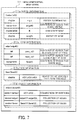
- FIG. 7 illustrates an example of a data structure of a three-dimensional mesh model.
- the three-dimensional mesh model 111 has vertex information 111 a , edge information 111 b , face information 111 c , and object information 111 d.
- the vertex information 111 a is provided for each vertex (node) in the three-dimensional mesh model 111 and is given an identifier (vID) of the vertex.
- the vertex information 111 a on a vertex includes the coordinates (x, y, z) of the vertex, identifiers (edgeID) of edges that share the vertex, a OEM coefficient (K) to be used for edge contraction, and a weight of the node.
- the edge information 111 b is provided for each edge in the three-dimensional mesh model 111 and is given an identifier (edgeID) of the edge.
- the edge information 111 b on an edge includes the identifier (prev_vID) of a vertex that is a start point of the edge, the identifier (next_vID) of a vertex that is an end point of the edge, and the identifiers (faceID) of faces that share the edge.
- the face information 111 c is provided for each face in the three-dimensional mesh model 111 and is given an identifier (faceID) of the face.
- faceID identifier
- the face information 111 c on a face includes the identifiers (vID 1 , vID 2 , vID 3 ) of vertices forming the triangular face.
- the object information 111 d is provided for each object (tetrahedral element) in the three-dimensional mesh model 111 and is given an identifier (objectID) of the object.
- the object information 111 d on an object includes a collection (vID 1 , vID 2 , . . . ) of vertices forming the object, a collection (edgeID 1 , edgeID 2 , . . . ) of edges forming the object, and a collection (faceID 1 , faceID 2 , . . . ) of faces forming the object.
- the three-dimensional mesh model 111 is defined by the above data structure. Triangular faces of objects in the three-dimensional mesh model 111 are meshes, and meshes are combined to each other to form one surface. Each triangular mesh is represented by three vertices and three edges connecting the vertices.
- the mesh reduction unit 130 moves two adjacent nodes to the same location to merge them into one node, thereby reducing the number of meshes. More specifically, the mesh reduction unit 130 removes one edge between the nodes to be merged and combine the both end nodes of the edge to generate a new node.
- the modeling apparatus 100 of the second embodiment is designed to reduce the number of meshes by collapsing edges.
- FIG. 8 illustrates an example of reducing the number of o 10 meshes by edge collapse.
- an edge 42 is collapsed by merging a node v 1 and a node v 2 .
- the nodes v 1 and v 2 are removed and a new node v 3 is generated.
- the edge connecting the nodes v 1 and v 2 is removed and new edges connecting to the newly generated node v 3 are generated. By doing so, two meshes that share the edge 42 are removed.
- a method of determining coordinates for the newly generated node v 3 takes an important role. For example, consider the case where the coordinates of a middle point between two nodes connected by an edge to be collapsed are set as new coordinates. In this case, as the mesh reduction progresses, the coordinates of a point that more deviate from the original shape are set as new coordinates, which results in losing the original shape. To keep the original shape as much as possible, the mesh reduction unit 130 calculates optimal coordinates taking the original shape into consideration. In the following, the meshes included in the original three-dimensional mesh model 111 are called original meshes.
- QEM squared distances
- a distance between the coordinates (x, y, z) and the plane is defined by
- w f denotes a weight for a mesh f based on the size or the like of the mesh f.
- K f is a matrix represented as follows:
- the QEM of a node v existing from before mesh reduction is calculated by the sum of squared distances between each plane of meshes holding the node v and the node v. Therefore, the QEMs of all nodes v existing from before the mesh reduction are calculated to be zero.
- the QEM of a node to be generated by collapsing an edge is calculated by the sum of QEMs for the planes of original meshes each holding any one of two nodes at both ends of the edge to be collapsed and nodes merged into the nodes.
- FIG. 9 illustrates relationship between a QEM value of a node and planes.
- FIG. 9 illustrates a plurality of planes 43 of original meshes each holding any one of two nodes at both ends of an edge to be collapsed and nodes merged into the nodes.
- FIG. 9 illustrates points as two possible coordinates for a new node to be generated by collapsing the edge. A point farther from the plurality of planes 43 has a higher QEM value, and a point closer to the plurality of planes 43 has a lower QEM value.
- the mesh reduction unit 130 takes coordinates that minimize the QEM value, as the coordinates of the new node. That is, coordinates that minimize the distances to meshes each holding any one of two nodes at both ends of an edge to be collapsed and nodes merged into the nodes are determined as the coordinates of the new node.
- the mesh reduction unit 130 gives an evaluation value to each edge and collapses edges in ascending order of their evaluation value. In this connection, a lower evaluation value is given to a shorter edge. This approach makes it possible to prevent triangular meshes from being too long and narrow after edge collapse.
- the mesh reduction unit 130 multiplies the length of the edge by a weight based on the thickness of a blood vessel to which the edge belongs, so as to set an appropriate mesh size according to the thickness of the blood vessel.
- the mesh reduction unit 130 provides each node with a 4-by-4 matrix for storing a QEM coefficient K and an area for storing a double-type weight node_weight, as a preparation for the reduction. Then, the mesh reduction unit 130 obtains the initial coefficient K and weight node_weight.
- the weight node_weight of a node is determined based on the thickness of a blood vessel and the type of the blood vessel determined from the thickness. In the second embodiment, it is assumed that aorta is represented by meshes that are three times as large as those for coronary artery.
- the mesh reduction unit 130 sets a weight w f for meshes belonging to the coronary artery to 3.0 and a weight w f for meshes belonging to the aorta to 1.0. Then, as the weight node_weight of a node, the mesh reduction unit 130 stores the average of w f values of all meshes sharing the node.
- the mesh reduction unit 130 calculates an evaluation value to be used for determining the order of collapse of edges, using the weights node_weight of nodes. For example, the mesh reduction unit 130 multiplies the length (edge_length) of an edge by the average of weights node_weight of the both end nodes of the edge and takes the multiplication result (edge_length ⁇ weight) as the evaluation value of the edge.
- FIG. 10 illustrates an example of weighting according to the thickness of a blood vessel.
- a weight for nodes representing the shape of the aortic root portion 31 is 1.0
- a weight for nodes representing the shape of the coronary artery 32 is 3.0.
- the evaluation value of the edge is calculated as “L1 ⁇ 1.0.”
- the evaluation value of the edge is calculated as “L2 ⁇ 3.0.”
- the edge in the aortic root portion 31 and the edge in the coronary artery 32 are the same in length, the edge in the coronary artery 32 has a higher evaluation value. In this case, by preferentially collapsing edges with low evaluation values, it is possible to preferentially collapse the aortic edges.
- the mesh reduction unit 130 uses a queue to efficiently select edges with low evaluation values.
- FIG. 11 illustrates an example of a queue for edge contraction.
- an edge contraction queue 51 collapse candidate edge information 52 of each edge, including the evaluation value and identifier (edgeID) of the edge, is registered.
- the collapse candidate edge information 52 in the queue 51 is sorted in ascending order of evaluation value.
- the mesh reduction unit 130 compares the already registered collapse candidate edge information 52 with the collapse candidate edge information 53 to be added in terms of evaluation value. Then, the mesh reduction unit 130 inserts the collapse candidate edge information 53 between the collapse candidate edge information 52 that has a lower evaluation value than the collapse candidate edge information 53 to be added and the collapse candidate edge information 52 that has a higher evaluation value than the collapse candidate edge information 53 to be added. In addition, when taking one piece of collapse candidate edge information out of the queue 51 , the mesh reduction unit 130 extracts the collapse candidate edge information 54 (with the lowest evaluation value) at the head of the queue 51 .
- the mesh reduction unit 130 collapses an extracted edge if the QEM of a new node to be generated by the collapse of the extracted edge is still below a threshold.
- edges are collapsed in ascending order of their length, and the second requirement of “to generate triangular meshes that are as close to equilateral triangles as possible” is satisfied. That is, when the number of meshes is reduced by collapsing edges, the lengths of surrounding edges become long. If long edges are collapsed with short edges remaining, surrounding meshes existing after the edge collapse become long and narrow. By contrast, by preferentially collapsing short edges, surrounding meshes existing after the edge collapse are expected to be close to equilateral triangles.
- a weight to be used in calculation of an evaluation value of an edge is determined according to the thickness of a blood vessel to which a mesh including the edge belongs. That is, the thinner a blood vessel, the higher the weight. Then, the higher the weight, the higher the evaluation value of the edge. This is because the evaluation value is calculated using the weight. If the edge has a higher evaluation value, the edge will be extracted as a collapse candidate at a later time point and thus has a lower possibility of being collapsed. Thus, the third requirement of “to determine appropriate sizes of meshes according to the thicknesses of blood vessels” is satisfied.
- Edge contraction is performed by removing the edge to be collapsed and all edges adjacent to the edge and then generating one new node and edges connecting to the node. Therefore, there is a possibility that collapse candidate edge information about an edge that no more exists remains in the queue 51 . It is not possible to perform the edge contraction process on such already removed edges. Therefore, when extracting collapse candidate edge information from the queue 51 , the mesh reduction unit 130 determines whether collapse of a corresponding edge is possible. If the collapse of the edge corresponding to the collapse candidate edge information extracted from the queue 51 is not determined possible, the mesh reduction unit 130 extracts new collapse candidate edge information from the queue 51 .
- the mesh reduction unit 130 uses a threshold to determine whether to collapse an edge. For example, when collapsing one edge, the mesh reduction unit 130 stores a QEM coefficient K and a weight node_weight in the node information of a newly generated node. The coefficient K and weight node_weight are the weighted averages of the corresponding values of two merged nodes. After that, the mesh reduction unit 130 generates a plurality of edges connecting to the new node and registers them in the queue. The evaluation value of an edge to be registered in the queue is calculated by multiplying the length of the edge by the weighted average of the weights node_weight of two nodes connected by the edge.
- FIG. 12 is a flowchart illustrating an example of the mesh reduction process. The following describes the process of FIG. 12 step by step.
- Step S 101 The mesh reduction unit 130 calculates QEM coefficients K ( ⁇ K f in equation (1)) with respect to all nodes.
- the mesh reduction unit 130 calculates the coefficient K of each node and sets it in the vertex information 111 a (see FIG. 7 ) of the node.
- the mesh reduction unit 130 calculates evaluation values with respect to all edges. For example, the mesh reduction unit 130 multiplies the length of an edge by the average of weights node_weight of two nodes connected by the edge, and takes the multiplication result as the evaluation value of the edge.
- Step S 103 The mesh reduction unit 130 registers the collapse candidate edge information corresponding to edges whose evaluation values are lower than or equal to an evaluation value threshold, in the queue.
- Each collapse candidate edge information includes the evaluation value and identifier (edgeID) of a corresponding edge.
- the mesh reduction unit 130 registers the collapse candidate edge information in the queue in ascending order of evaluation value.
- Step S 104 The mesh reduction unit 130 extracts the collapse candidate edge information one by one in order from the one placed at the head of the queue, and performs the edge contraction process of steps S 105 to S 110 .
- steps S 105 to S 110 whether collapse of an edge indicated in the collapse candidate edge information is possible is determined and, if the collapse of the edge is determined possible, the edge is subjected to a collapse process.
- Step S 105 The mesh reduction unit 130 takes the edge corresponding to the extracted collapse candidate edge information as a collapse candidate, and calculates the QEM of a node to be generated by the collapse of the edge.
- Step S 106 The mesh reduction unit 130 determines whether the collapse of the collapse candidate edge is possible. For example, there may be a case where the collapse candidate edge has been removed according to collapse of an edge adjacent to the collapse candidate edge. In this case, the collapse candidate edge is already removed and so its collapse is not possible. If the collapse of the collapse candidate edge is possible, the process proceeds to step S 107 . Otherwise, the process proceeds to step S 111 .
- Step S 107 The mesh reduction unit 130 determines whether the value calculated by multiplying the QEM of the node to be generated by the collapse of the collapse candidate edge by a corresponding weight is lower than a QEM threshold (maxcost). For example, the mesh reduction unit 130 obtains the coefficients K from the node information of both end nodes of the collapse candidate edge. Then, the mesh reduction unit 130 takes the sum of the coefficients K of the nodes as the coefficient K of the new node to be generated. Further, the mesh reduction unit 130 calculates the coordinates of the node v that minimize the QEM of the new node, with the equation (3). The mesh reduction unit 130 calculates the QEM of the new node to be generated with the equation (1) using the coordinates of the node v that minimize the QEM.
- a QEM threshold maxcost
- the mesh reduction unit 130 multiplies the calculated QEM by the weight and compares the multiplication result with the QEM threshold.
- the weight for the new node to be generated is the average of weights of both end nodes of the collapse candidate edge, for example.
- step S 108 If the result of multiplying the QEM by the weight is lower than the QEM threshold, the process proceeds to step S 108 . Otherwise, the process proceeds to step S 111 .
- Step S 108 The mesh reduction unit 130 collapses the collapse candidate edge and generates a new node. For example, the mesh reduction unit 130 removes the collapse candidate edge and other elements (edges, nodes, meshes, objects) to be removed according to the collapse of the collapse candidate edge. The mesh reduction unit 130 then generates the new node into which the both end nodes of the collapse candidate edge are merged, at a position that minimizes the QEM. Then, the mesh reduction unit 130 generates edges connecting to the new node, meshes having the generated edges, and objects having the generated meshes.
- Step S 109 The mesh reduction unit 130 calculates a coefficient K and weight of the generated node.
- Step S 110 The mesh reduction unit 130 calculates an evaluation value of each generated edge. Then the mesh reduction unit 130 registers collapse candidate edge information corresponding to an edge in the queue if the calculated evaluation value of the edge is lower than or equal to the evaluation value threshold.
- Step S 111 The mesh reduction unit 130 repeats steps S 105 to S 110 if the queue includes a collapse candidate edge that is not yet processed. If the queue does not include any unprocessed collapse candidate edge, the mesh reduction unit 130 completes the mesh reduction process.
- FIG. 13 illustrates examples of reducing the number of meshes in a long thin model.
- FIG. 13 illustrates examples of performing a mesh reduction process on a cylindrical three-dimensional mesh model 61 , on the basis of the lengths of edges (second embodiment) and on the basis of QEM values (comparative example).
- a node to be generated by collapse of an edge is placed at a position that minimizes QEM.
- edges are collapsed in ascending order of QEM of new nodes to be generated by edge collapse.
- the shapes of meshes after the edge collapse are not taken into account.
- long narrow triangular meshes are generated as illustrated in FIG. 13 .
- the meshes generated by the edge collapse are shaped close to equilateral triangles.
- FIG. 14 illustrates examples of changes in a model shape at the time of mesh reduction.
- FIG. 14 illustrates examples of performing a mesh reduction process on a donut-shaped three-dimensional mesh model 62 , on the basis of the lengths of edges (second embodiment) and on the basis of QEM values (comparative example).
- a node to be generated by collapse of an edge is placed at a position that minimizes QEM.
- the original three-dimensional mesh model 62 has 4032 nodes.
- To perform the mesh reduction process on the three-dimensional mesh model 62 gradually reduces the number of nodes and changes the shape of the model.
- the mesh model fails to keep its donut shape along with the reduction in the number of nodes.
- the mesh model keeps its donut shape even after the number of nodes is reduced.
- weighting is performed according to the thicknesses of blood vessels so that the mesh reduction does not increase the size of meshes forming thin portions too much. As a result, it is possible to reduce the number of meshes without greatly losing the original shape of the three-dimensional mesh model in which thick portions and thin portions coexist.
- FIG. 15 illustrates an example of mesh reduction in a three-dimensional mesh model having portions of different thicknesses.
- FIG. 15 illustrates an original coronary artery model 63 (before mesh reduction) and a coronary artery model 64 (after mesh reduction).
- the coronary artery model 63 includes a thick aortic root portion and a thin coronary artery. After the mesh reduction, the aorta and the coronary artery are represented by meshes of different sizes, and the boundary portion therebetween does not have narrow and pointed meshes due to a sudden change in mesh size but has made a favorable change.
- the second embodiment is designed to collapse edges in ascending order of their length and generate new nodes at positions that minimize QEMs, so that it is possible to generate triangular meshes that are as close to equilateral triangles as possible while keeping the original shape.
- this approach makes it possible that a three-dimensional mesh model that is long and thin like a blood vessel keeps its original shape even when the number of meshes is greatly reduced.
- the second embodiment is designed to use the length of an edge in calculation of an evaluation value.
- another index may be usable for calculating the evaluation value.
- an aspect ratio of a mesh may be used for this purpose.
- the aspect ratio is a radius ratio of an inner circle to an outer circle of a triangle representing a mesh, for example.
- the radius of the inner circle of the mesh is divided by the radius of the outer circle of the mesh, and a result of multiplying the division result by a prescribed constant value may be used as the aspect ratio.
- the constant value used in the multiplication is determined such that the aspect ratio of the mesh becomes one when the mesh is an equilateral triangle.
- the mesh reduction unit 130 selects meshes in descending order of their aspect ratio and collapses the shortest edge included in the selected mesh.
Landscapes
- Engineering & Computer Science (AREA)
- Physics & Mathematics (AREA)
- Theoretical Computer Science (AREA)
- General Physics & Mathematics (AREA)
- Geometry (AREA)
- Software Systems (AREA)
- Computer Graphics (AREA)
- General Engineering & Computer Science (AREA)
- Evolutionary Computation (AREA)
- Computer Hardware Design (AREA)
- Apparatus For Radiation Diagnosis (AREA)
- Image Generation (AREA)
- Processing Or Creating Images (AREA)
Abstract
Description
Claims (8)
Applications Claiming Priority (1)
| Application Number | Priority Date | Filing Date | Title |
|---|---|---|---|
| PCT/JP2017/001549 WO2018134914A1 (en) | 2017-01-18 | 2017-01-18 | Modeling device, modeling method, and modeling program |
Related Parent Applications (1)
| Application Number | Title | Priority Date | Filing Date |
|---|---|---|---|
| PCT/JP2017/001549 Continuation WO2018134914A1 (en) | 2017-01-18 | 2017-01-18 | Modeling device, modeling method, and modeling program |
Publications (2)
| Publication Number | Publication Date |
|---|---|
| US20190333271A1 US20190333271A1 (en) | 2019-10-31 |
| US10692282B2 true US10692282B2 (en) | 2020-06-23 |
Family
ID=62907839
Family Applications (1)
| Application Number | Title | Priority Date | Filing Date |
|---|---|---|---|
| US16/507,038 Active US10692282B2 (en) | 2017-01-18 | 2019-07-10 | Modeling apparatus and modeling method |
Country Status (4)
| Country | Link |
|---|---|
| US (1) | US10692282B2 (en) |
| JP (1) | JP6748368B2 (en) |
| CN (1) | CN110214342A (en) |
| WO (1) | WO2018134914A1 (en) |
Families Citing this family (4)
| Publication number | Priority date | Publication date | Assignee | Title |
|---|---|---|---|---|
| WO2018201437A1 (en) * | 2017-05-05 | 2018-11-08 | 上海联影医疗科技有限公司 | Image segmentation method and system |
| CN111553978B (en) * | 2020-04-28 | 2023-09-19 | 上海无线电设备研究所 | A three-dimensional rough model modeling method based on triangular mesh elements |
| WO2023228289A1 (en) * | 2022-05-24 | 2023-11-30 | 日本電信電話株式会社 | Video correction device, video correction method, and program |
| CN115582980A (en) * | 2022-09-26 | 2023-01-10 | 武汉嘉晨电子技术有限公司 | Method for adjusting double-layer grid in modular flow analysis |
Citations (10)
| Publication number | Priority date | Publication date | Assignee | Title |
|---|---|---|---|---|
| JPH0652271A (en) | 1992-06-24 | 1994-02-25 | Nippon Telegr & Teleph Corp <Ntt> | Simulation method for three-dimensional lsi shape |
| EP1113400A2 (en) | 1999-12-27 | 2001-07-04 | Minolta Co., Ltd. | Method and apparatus for reducing three-dimensional shape data |
| JP2001184528A (en) | 1999-12-27 | 2001-07-06 | Minolta Co Ltd | Method and device for reducing number of three- dimensional shape data |
| US20010013866A1 (en) * | 1999-01-27 | 2001-08-16 | Alexander Migdal | Adaptive subdivision of mesh models |
| US20010056308A1 (en) * | 2000-03-28 | 2001-12-27 | Michael Petrov | Tools for 3D mesh and texture manipulation |
| JP2003323637A (en) | 2002-04-30 | 2003-11-14 | Japan Science & Technology Corp | Image data compression processing method and image processing apparatus |
| US20050099420A1 (en) * | 1998-07-14 | 2005-05-12 | Microsoft Corporation | Regional progressive meshes |
| US20060050073A1 (en) | 2004-08-31 | 2006-03-09 | Satoshi Kanai | Tetrahedral mesh generating method and program |
| WO2009096891A1 (en) | 2008-02-01 | 2009-08-06 | Donya Labs Ab | Real-time user guided optimization of general 3d data |
| US20130300741A1 (en) * | 2012-05-14 | 2013-11-14 | Autodesk, Inc. | Adaptive mesh refinement |
-
2017
- 2017-01-18 CN CN201780083810.XA patent/CN110214342A/en active Pending
- 2017-01-18 JP JP2018562782A patent/JP6748368B2/en active Active
- 2017-01-18 WO PCT/JP2017/001549 patent/WO2018134914A1/en not_active Ceased
-
2019
- 2019-07-10 US US16/507,038 patent/US10692282B2/en active Active
Patent Citations (15)
| Publication number | Priority date | Publication date | Assignee | Title |
|---|---|---|---|---|
| US5377118A (en) | 1992-06-24 | 1994-12-27 | Intel Corporation | Method for accurate calculation of vertex movement for three-dimensional topography simulation |
| JPH0652271A (en) | 1992-06-24 | 1994-02-25 | Nippon Telegr & Teleph Corp <Ntt> | Simulation method for three-dimensional lsi shape |
| US20050099420A1 (en) * | 1998-07-14 | 2005-05-12 | Microsoft Corporation | Regional progressive meshes |
| US20010013866A1 (en) * | 1999-01-27 | 2001-08-16 | Alexander Migdal | Adaptive subdivision of mesh models |
| US20020003539A1 (en) | 1999-12-27 | 2002-01-10 | Yoshihisa Abe | Method and apparatus for reducing three-dimensional shape data |
| JP2001184528A (en) | 1999-12-27 | 2001-07-06 | Minolta Co Ltd | Method and device for reducing number of three- dimensional shape data |
| EP1113400A2 (en) | 1999-12-27 | 2001-07-04 | Minolta Co., Ltd. | Method and apparatus for reducing three-dimensional shape data |
| US20010056308A1 (en) * | 2000-03-28 | 2001-12-27 | Michael Petrov | Tools for 3D mesh and texture manipulation |
| JP2003323637A (en) | 2002-04-30 | 2003-11-14 | Japan Science & Technology Corp | Image data compression processing method and image processing apparatus |
| US20050219237A1 (en) | 2002-04-30 | 2005-10-06 | Akio Doi | Image data compression method and image processing device |
| US20060050073A1 (en) | 2004-08-31 | 2006-03-09 | Satoshi Kanai | Tetrahedral mesh generating method and program |
| JP2006072490A (en) | 2004-08-31 | 2006-03-16 | Hokkaido Univ | Tetrahedral mesh generation method and program |
| WO2009096891A1 (en) | 2008-02-01 | 2009-08-06 | Donya Labs Ab | Real-time user guided optimization of general 3d data |
| US20110050691A1 (en) | 2008-02-01 | 2011-03-03 | Koshjar Hamedi | Real-time user guided optimization of general 3d data |
| US20130300741A1 (en) * | 2012-05-14 | 2013-11-14 | Autodesk, Inc. | Adaptive mesh refinement |
Non-Patent Citations (3)
| Title |
|---|
| Garland et al., "Surface Simplification Using Quadric Error Metrics", Carnegie Mellon University, Proceedings of the 24th annual conference on Computer graphics and interactive techniques, Aug. 3-8, 1997, pp. 209-216. |
| International Search Report and Written Opinion dated Mar. 21, 2017 for PCT/JP2017/001549 filed on Jan. 18, 2017, 11 pages including English Translation of the International Search Report and Written Opinion. |
| Office Action dated Apr. 21, 2020 for corresponding Japanese Patent Application No. 2018-562782, with English Translation, 6 pages. |
Also Published As
| Publication number | Publication date |
|---|---|
| US20190333271A1 (en) | 2019-10-31 |
| WO2018134914A1 (en) | 2018-07-26 |
| JPWO2018134914A1 (en) | 2019-11-07 |
| JP6748368B2 (en) | 2020-09-02 |
| CN110214342A (en) | 2019-09-06 |
Similar Documents
| Publication | Publication Date | Title |
|---|---|---|
| US10692282B2 (en) | Modeling apparatus and modeling method | |
| Cebral et al. | Efficient pipeline for image-based patient-specific analysis of cerebral aneurysm hemodynamics: technique and sensitivity | |
| JP7829480B2 (en) | Method and system for determining the likelihood of regional rupture of blood vessels | |
| US10896508B2 (en) | System for segmentation of anatomical structures in cardiac CTA using fully convolutional neural networks | |
| US10325369B2 (en) | Method and system for analyzing blood flow condition | |
| Danilov et al. | Methods of graph network reconstruction in personalized medicine | |
| US9123169B2 (en) | Model generation method and model generation apparatus | |
| CN108280827B (en) | Method, system and device for automatic detection of coronary artery lesions based on deep learning | |
| US7574247B2 (en) | Automatic coronary isolation using a n-MIP ray casting technique | |
| US10262762B2 (en) | Apparatus for generating first vascular data having a tree structure based on anatomical data and generating second vascular data without relying on the anatomical data | |
| US10891787B2 (en) | Apparatus and method for creating biological model | |
| Thamsen et al. | Synthetic database of aortic morphometry and hemodynamics: overcoming medical imaging data availability | |
| WO2016182508A1 (en) | Medical image processing methods and systems | |
| JP2007289704A (en) | System and method for semi-automated analysis of aortic aneurysms | |
| Dillard et al. | From medical images to flow computations without user‐generated meshes | |
| Wang et al. | GPU acceleration of Volumetric Lattice Boltzmann Method for patient-specific computational hemodynamics | |
| Scarpolini et al. | Enabling supra-aortic vessels inclusion in statistical shape models of the aorta: a novel non-rigid registration method | |
| Sazonov et al. | Modelling pipeline for subject‐specific arterial blood flow—a review | |
| Yang et al. | A benchmark study of convolutional neural networks in fully automatic segmentation of aortic root | |
| US10699479B2 (en) | Apparatus and method for generating biological model | |
| Cai et al. | LABEL-SAM: A Semi-Automatic Interactive Annotation Model for Aortic Dissection Segmentation in 3D CTA Image | |
| Veress et al. | The direct incorporation of perfusion defect information to define ischemia and infarction in a finite element model of the left ventricle | |
| Bereska et al. | SACP: Spatially-Adaptive Conformal Prediction in Uncertainty Quantification of Medical Image Segmentation | |
| Fedele et al. | Semi-automatic three-dimensional vessel segmentation using a connected component localization of the region-scalable fitting energy | |
| Csippa | Hemodynamics of arterial malformations: intracranial aneurysms and coronary artery disease |
Legal Events
| Date | Code | Title | Description |
|---|---|---|---|
| FEPP | Fee payment procedure |
Free format text: ENTITY STATUS SET TO UNDISCOUNTED (ORIGINAL EVENT CODE: BIG.); ENTITY STATUS OF PATENT OWNER: LARGE ENTITY |
|
| AS | Assignment |
Owner name: FUJITSU LIMITED, JAPAN Free format text: ASSIGNMENT OF ASSIGNORS INTEREST;ASSIGNOR:NAKAGAWA, MACHIKO;REEL/FRAME:049964/0377 Effective date: 20190714 |
|
| AS | Assignment |
Owner name: FUJITSU LIMITED, JAPAN Free format text: ASSIGNMENT OF ASSIGNORS INTEREST;ASSIGNOR:NAKAGAWA, MACHIKO;REEL/FRAME:049994/0692 Effective date: 20190714 |
|
| STPP | Information on status: patent application and granting procedure in general |
Free format text: DOCKETED NEW CASE - READY FOR EXAMINATION |
|
| STPP | Information on status: patent application and granting procedure in general |
Free format text: NOTICE OF ALLOWANCE MAILED -- APPLICATION RECEIVED IN OFFICE OF PUBLICATIONS |
|
| STPP | Information on status: patent application and granting procedure in general |
Free format text: PUBLICATIONS -- ISSUE FEE PAYMENT VERIFIED |
|
| STCF | Information on status: patent grant |
Free format text: PATENTED CASE |
|
| MAFP | Maintenance fee payment |
Free format text: PAYMENT OF MAINTENANCE FEE, 4TH YEAR, LARGE ENTITY (ORIGINAL EVENT CODE: M1551); ENTITY STATUS OF PATENT OWNER: LARGE ENTITY Year of fee payment: 4 |