US1069204A - Bake-pan. - Google Patents
Bake-pan. Download PDFInfo
- Publication number
- US1069204A US1069204A US69077812A US1912690778A US1069204A US 1069204 A US1069204 A US 1069204A US 69077812 A US69077812 A US 69077812A US 1912690778 A US1912690778 A US 1912690778A US 1069204 A US1069204 A US 1069204A
- Authority
- US
- United States
- Prior art keywords
- pan
- strip
- bake
- bead
- pans
- Prior art date
- Legal status (The legal status is an assumption and is not a legal conclusion. Google has not performed a legal analysis and makes no representation as to the accuracy of the status listed.)
- Expired - Lifetime
Links
- 239000011324 bead Substances 0.000 description 26
- 230000003014 reinforcing effect Effects 0.000 description 12
- 230000002787 reinforcement Effects 0.000 description 9
- XEEYBQQBJWHFJM-UHFFFAOYSA-N Iron Chemical compound [Fe] XEEYBQQBJWHFJM-UHFFFAOYSA-N 0.000 description 2
- 235000008429 bread Nutrition 0.000 description 2
- 238000004519 manufacturing process Methods 0.000 description 2
- ATJFFYVFTNAWJD-UHFFFAOYSA-N Tin Chemical compound [Sn] ATJFFYVFTNAWJD-UHFFFAOYSA-N 0.000 description 1
- 239000011248 coating agent Substances 0.000 description 1
- 238000000576 coating method Methods 0.000 description 1
- 229910052742 iron Inorganic materials 0.000 description 1
- JEIPFZHSYJVQDO-UHFFFAOYSA-N iron(III) oxide Inorganic materials O=[Fe]O[Fe]=O JEIPFZHSYJVQDO-UHFFFAOYSA-N 0.000 description 1
- 230000002045 lasting effect Effects 0.000 description 1
- 239000000463 material Substances 0.000 description 1
- 238000000034 method Methods 0.000 description 1
- 239000005028 tinplate Substances 0.000 description 1
Images
Classifications
-
- B—PERFORMING OPERATIONS; TRANSPORTING
- B65—CONVEYING; PACKING; STORING; HANDLING THIN OR FILAMENTARY MATERIAL
- B65D—CONTAINERS FOR STORAGE OR TRANSPORT OF ARTICLES OR MATERIALS, e.g. BAGS, BARRELS, BOTTLES, BOXES, CANS, CARTONS, CRATES, DRUMS, JARS, TANKS, HOPPERS, FORWARDING CONTAINERS; ACCESSORIES, CLOSURES, OR FITTINGS THEREFOR; PACKAGING ELEMENTS; PACKAGES
- B65D88/00—Large containers
- B65D88/02—Large containers rigid
- B65D88/10—Large containers rigid parallelepipedic
Definitions
- FRANK I TH-IEN AND FRANK G. GUENTHER, OF CHICAGO, ILLINOIS.
- FRANK P. THIEN and FRANK G. GUENTHER citizens of the United States, and residents of the city of Chicago, .5 in the county of Cook and State of Illinois,
- This invention has general reference to improvements in bake'pans; in particular, to that class ofpans for baking bread in commercial bake shops.
- the object of our invention is the production of a cheap, yet at the same time efficient bake pan, possessing lasting qualities beyond such as at present produced. Another object is to provide a reinforcement for the pans at a point where the impact of a blow from the bakers peel is usually delivered when forcing the vsame under the pans when they are removed from the bake oven.
- the punctures'in thc tin plate exposes the black iron under the tin coating and renders 40 it susceptible to rust. Moreover, the rivet heads on the inner surface of the pans mar the smooth interior thereof, and makes the removal of the baked bread more difficult.
- our invention contemplates the production of a reinforcement which is applied to the outer pans of a set (usually four pans affixed together in spaced relatlon to each other with spaces between each pan, to insure even baking of the contents) without the use of rivets, screws, or studs and without puncturing, mutilating, or otherwise defacing 'the interior walls of the pans. It further contemplates a further rcmforcement at the point of impact of the peel, and novel means for deliecting the point of said proper ⁇ impact to the place of greatest reinforcement.
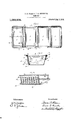
- Figure 1 is a plan of a set of four pansor trays comprising a so-called bake pan.
- Fig. 2 is a transverse sectional elevation in line Y. Y. of Fig. l.'
- Fig. 3 is a perspective view of the reinforcing members before being attached to the pans or trays.
- Like parts are designated by correspondmg symbols or characters of reference in all the figures.
- Our bake pan comprises a setI of usually four rectangular' trays 1, having bottoms 2, sides 3, and ends 4, all preferably formed up from a single sheet, with overlapping folds 5, for stiffening purposes at thecorners. These trays are connected in spaced relation to each other by light metallic bars 6 and rivets 7 there being punctures 8, in the ends of the trays and corresponding holes in the sides of the bars 6, to receive the rivets 7, already mentioned.
- the upper edges of the sides 3 and ends 4 are curled outwardly at 8, 9, and 9', to embraceand curl around a wire 10, which is bent into rectangular cont-our, and also to inclose beads ll and 12, of the pan reinforcement hereinafter to be described.
- These curled portions 8, 9, and 9' therefore serve the double purpose of not only stiffening the upper edges of the trays or pans, but also form the lock or hold of the reinforcing members. It should now be understood that our reinforcement is only applied to the outer sides of the exterior pans or trays of the set, they being the only ones that come in vcontact with the bakers peel.
- the reinforcement already referred to consists, first, of 'a comparatively light metallic strip A, the length of which is slightly less than that ofthe side 3 of the pan or tray 1, and of a width nearly equal to the depth thereof. Along its upper edge is formed an open U-shaped bead or curl 11, which embraces the wire 10, already mentioned and is embraced by the curled ⁇ portion 9, hereinbefore referred to. On the lower edge of this strip A, is formed a turned edge 13,v
- a wire C which totally incloses a wire C. as shown in Figs. 2 and 3.
- This wire is bent into the shape of an open rectangle and passes around the ends ofjthe pan or tray to the opposite side where it is locked ina turned edge 14 of a metallic strip B, at a point nearly adjacent to the top edge of the tray.
- This strip B has an open U-shaped bead 12, along its upper edge which passes over the wire 6, before mentioned, and is held in position thereon by the curled portion 9', in the same manner as the bead 11 of the strip A is held in fixed position by the curl 9 of the pan or tray 1.
- rlhese corrugations 15 serve a' triple function; first, enabling us to make the strip A of much lighter material than would otherwise be possible; second, in imparting greater stiffness to the strip to resist the irnpact of the bakers peel, and, lastly, thelower edge terminating abruptly, will defiect the point of the peel downwardly to the point 17, where the reinforcmeent is greatest by reason of the backing of the wire C, so that the impact of the blow is taken at the point where the reinforcement is best able to absorb it. lt will now be observed that forming the edge 13 on the inside of the strip A, we secure an air space 18, between it and the side of the pan or tray, allowing ample heat circulation therebetween and thereby not impeding the evenness of the baking processes.
- i bake pan comprising a bottom, sides, ends, and beads along the upper edges thereof, a reinforcing strip for one side of said pan having its upper edge embraced by the bead on said side, means engaging the lower edge of said strip, said means extending to the opposite side of said pan, and means there located to maintain the first mentioned means in position.
- a bake pan comprising a bottom, sides,
- a reinforcing strip for one side of said pan having its upper edge embraced by the bead on said side, means engaging the lower edge of said strip and extending around the ends of said pan to the opposite side thereof, and means there located to maintain the iirst mentioned means in position.
- a bake pan comprising a bottom, sides,
- a reinforcing strip for one side of said pan having its upper edge embraced by the bead on said side, means engaging the lower edge of said strip and extending parallel to the ends of said pan, and adjacent thereto, to t-he'opposite side of said pan, and means there located to retain first mentioned means in position.
- a bake pan comprising a bottom, sides, ends, and beads along the upper edges thereof, a reinforcing strip for one sideof said pan having its upper edge embraced by the bead on said side, a bead along the lower edge of said strip, a wire engaging said bead, and extending parallel to the ends of said pan, and adjacent thereto, to the opposite side of said pan, and means there located to retain said wire in position.
- a bake pan comprising a bottom, sides, ends, and beads along the upper edges thereof, a reinforcing strip for one side of said pan having its upper edge embraced by the bead on said side, an inturned bead along the lower edge of said strip, a series of vertical corrugations throughout the length of said strip merging into said strip near its upper edge and terminating abruptly above said inturned bead, and means engaging said bead and connecting the same with the opposite side of said pan.
- a bake pan comprising a bottom, sides ends, and beads along the upper edges thereof, a reinforcing strip for one side of said pan. having its upper edge embraced by thev bead on said side, a depending strip on the opposite side of said pan having its upper edge embraced by the bead on that side, and means connecting the lower edges of both of said strips.
- a bake pan comprising a bottom, sides, ends, and beads along the upper edges thereof, a reinforcing strip for one side of said pan having its upper edge embraced by the bead on said side, an inturned bead along the lower edge of said strip, a wire bent in the form of an open rect-angle. engaged by said inturned bead and embracing said pan, and means for retaining said wire in contact with said pan on the side opposite said reinforcing strip.
Landscapes
- Engineering & Computer Science (AREA)
- Mechanical Engineering (AREA)
- Cookers (AREA)
Description
F. P. THIEN & P. G. GUENTHER.
BAKE PAN.
APrLIoATIoN FILED APR. 15. 1912.
1,069,204. Patented Aug. 5, 1913.
f f @UM-@@di UNTTED STATES PATENT FFICE.
FRANK I. TH-IEN AND FRANK G. GUENTHER, OF CHICAGO, ILLINOIS.
BAKE-PAN.
Specicaton of Letters Patent.
Application filed April 15, 1912.
Patented Aug.5,1913. Serial No. 690,778.
To all 'whom t may concern: y
Be it known that we, FRANK P. THIEN and FRANK G. GUENTHER, citizens of the United States, and residents of the city of Chicago, .5 in the county of Cook and State of Illinois,
have invented' certain new and useful-Improvements in Bake-Pans; and we do hereby declarel that the following description of our said invention', taken in connection with the accompanying sheet ofv drawings, forms a full, clear, and exact specification, which will enable others skilled in the art to which it appertains to make and use the same.
This invention has general reference to improvements in bake'pans; in particular, to that class ofpans for baking bread in commercial bake shops.
lt consists, essentially, in the novel and peculiar combination of parts as hereinafter first fullyset forth and described, and then pointed out in the claims.
The object of our invention is the production of a cheap, yet at the same time efficient bake pan, possessing lasting qualities beyond such as at present produced. Another object is to provide a reinforcement for the pans at a point where the impact of a blow from the bakers peel is usually delivered when forcing the vsame under the pans when they are removed from the bake oven.
We are aware that bake pans with reinforcements have been made before, but in all such` cases the reinforcing members have been riveted to the pan proper, necessitating the puncturing of the walls of the an and reinforcement for. the reception o rivets. This is an objectionable feature, as
the punctures'in thc tin plate exposes the black iron under the tin coating and renders 40 it susceptible to rust. Moreover, the rivet heads on the inner surface of the pans mar the smooth interior thereof, and makes the removal of the baked bread more difficult.
Therefore, our invention contemplates the production of a reinforcement which is applied to the outer pans of a set (usually four pans affixed together in spaced relatlon to each other with spaces between each pan, to insure even baking of the contents) without the use of rivets, screws, or studs and without puncturing, mutilating, or otherwise defacing 'the interior walls of the pans. It further contemplates a further rcmforcement at the point of impact of the peel, and novel means for deliecting the point of said proper` impact to the place of greatest reinforcement.
In' the drawings already referred to, which serve to illustrate our invention more fully, Figure 1 is a plan of a set of four pansor trays comprising a so-called bake pan. Fig. 2 is a transverse sectional elevation in line Y. Y. of Fig. l.' Fig. 3 is a perspective view of the reinforcing members before being attached to the pans or trays. Like parts are designated by correspondmg symbols or characters of reference in all the figures.
Our bake pan comprises a setI of usually four rectangular' trays 1, having bottoms 2, sides 3, and ends 4, all preferably formed up from a single sheet, with overlapping folds 5, for stiffening purposes at thecorners. These trays are connected in spaced relation to each other by light metallic bars 6 and rivets 7 there being punctures 8, in the ends of the trays and corresponding holes in the sides of the bars 6, to receive the rivets 7, already mentioned.
.The upper edges of the sides 3 and ends 4 are curled outwardly at 8, 9, and 9', to embraceand curl around a wire 10, which is bent into rectangular cont-our, and also to inclose beads ll and 12, of the pan reinforcement hereinafter to be described. These curled portions 8, 9, and 9', therefore serve the double purpose of not only stiffening the upper edges of the trays or pans, but also form the lock or hold of the reinforcing members. It should now be understood that our reinforcement is only applied to the outer sides of the exterior pans or trays of the set, they being the only ones that come in vcontact with the bakers peel.
The reinforcement already referred to consists, first, of 'a comparatively light metallic strip A, the length of which is slightly less than that ofthe side 3 of the pan or tray 1, and of a width nearly equal to the depth thereof. Along its upper edge is formed an open U-shaped bead or curl 11, which embraces the wire 10, already mentioned and is embraced by the curled `portion 9, hereinbefore referred to. On the lower edge of this strip A, is formed a turned edge 13,v
.which totally incloses a wire C. as shown in Figs. 2 and 3. This wire is bent into the shape of an open rectangle and passes around the ends ofjthe pan or tray to the opposite side where it is locked ina turned edge 14 of a metallic strip B, at a point nearly adjacent to the top edge of the tray. This strip B, has an open U-shaped bead 12, along its upper edge which passes over the wire 6, before mentioned, and is held in position thereon by the curled portion 9', in the same manner as the bead 11 of the strip A is held in fixed position by the curl 9 of the pan or tray 1.
In the face of the reinforcing strip A, are formed a series of deep, sharp corrugations 15, the entire length thereof and extending laterally of the` strip. They merge into the face of the strip at a point slightly below the head 11, at the upper end, and terminate abruptly at 16, Fig. 2, near the lower end. rlhese corrugations 15 serve a' triple function; first, enabling us to make the strip A of much lighter material than would otherwise be possible; second, in imparting greater stiffness to the strip to resist the irnpact of the bakers peel, and, lastly, thelower edge terminating abruptly, will defiect the point of the peel downwardly to the point 17, where the reinforcmeent is greatest by reason of the backing of the wire C, so that the impact of the blow is taken at the point where the reinforcement is best able to absorb it. lt will now be observed that forming the edge 13 on the inside of the strip A, we secure an air space 18, between it and the side of the pan or tray, allowing ample heat circulation therebetween and thereby not impeding the evenness of the baking processes.
Having thus fully described our invention, we claim as new and desire to secure to us by Letters Patent of the-United States 1. i bake pan comprising a bottom, sides, ends, and beads along the upper edges thereof, a reinforcing strip for one side of said pan having its upper edge embraced by the bead on said side, means engaging the lower edge of said strip, said means extending to the opposite side of said pan, and means there located to maintain the first mentioned means in position.
2. A bake pan comprising a bottom, sides,
ends, and beads along the upper edges thereof, a reinforcing strip for one side of said pan having its upper edge embraced by the bead on said side, means engaging the lower edge of said strip and extending around the ends of said pan to the opposite side thereof, and means there located to maintain the iirst mentioned means in position.
3. A bake pan comprising a bottom, sides,
ends, and beads along the upper edges thereof, a reinforcing strip for one side of said pan having its upper edge embraced by the bead on said side, means engaging the lower edge of said strip and extending parallel to the ends of said pan, and adjacent thereto, to t-he'opposite side of said pan, and means there located to retain first mentioned means in position.
4. A bake pan comprising a bottom, sides, ends, and beads along the upper edges thereof, a reinforcing strip for one sideof said pan having its upper edge embraced by the bead on said side, a bead along the lower edge of said strip, a wire engaging said bead, and extending parallel to the ends of said pan, and adjacent thereto, to the opposite side of said pan, and means there located to retain said wire in position.
5. A bake pan comprising a bottom, sides, ends, and beads along the upper edges thereof, a reinforcing strip for one side of said pan having its upper edge embraced by the bead on said side, an inturned bead along the lower edge of said strip, a series of vertical corrugations throughout the length of said strip merging into said strip near its upper edge and terminating abruptly above said inturned bead, and means engaging said bead and connecting the same with the opposite side of said pan.
6. A bake pan comprising a bottom, sides ends, and beads along the upper edges thereof, a reinforcing strip for one side of said pan. having its upper edge embraced by thev bead on said side, a depending strip on the opposite side of said pan having its upper edge embraced by the bead on that side, and means connecting the lower edges of both of said strips.
7. A bake pan -comprising a bottom, sides, ends, and beads along the upper edges thereof, a reinforcing strip for one side of said pan having its upper edge embraced by the bead on said side, an inturned bead along the lower edge of said strip, a wire bent in the form of an open rect-angle. engaged by said inturned bead and embracing said pan, and means for retaining said wire in contact with said pan on the side opposite said reinforcing strip.
FRANK P. Ciltlllhl. FRANK G. Glllllil'lldillt.
Witnesses KATE S. HOLMES, lflirrraiir @L STARK.
Priority Applications (1)
| Application Number | Priority Date | Filing Date | Title |
|---|---|---|---|
| US69077812A US1069204A (en) | 1912-04-15 | 1912-04-15 | Bake-pan. |
Applications Claiming Priority (1)
| Application Number | Priority Date | Filing Date | Title |
|---|---|---|---|
| US69077812A US1069204A (en) | 1912-04-15 | 1912-04-15 | Bake-pan. |
Publications (1)
| Publication Number | Publication Date |
|---|---|
| US1069204A true US1069204A (en) | 1913-08-05 |
Family
ID=3137442
Family Applications (1)
| Application Number | Title | Priority Date | Filing Date |
|---|---|---|---|
| US69077812A Expired - Lifetime US1069204A (en) | 1912-04-15 | 1912-04-15 | Bake-pan. |
Country Status (1)
| Country | Link |
|---|---|
| US (1) | US1069204A (en) |
Cited By (2)
| Publication number | Priority date | Publication date | Assignee | Title |
|---|---|---|---|---|
| US4740042A (en) * | 1987-03-02 | 1988-04-26 | General Electric Company | Appliance door having stiffened inner panel with shelves and method of forming |
| US8348089B2 (en) | 2010-05-06 | 2013-01-08 | American Pan Company | Industrial baking tray with contoured reinforcement band |
-
1912
- 1912-04-15 US US69077812A patent/US1069204A/en not_active Expired - Lifetime
Cited By (2)
| Publication number | Priority date | Publication date | Assignee | Title |
|---|---|---|---|---|
| US4740042A (en) * | 1987-03-02 | 1988-04-26 | General Electric Company | Appliance door having stiffened inner panel with shelves and method of forming |
| US8348089B2 (en) | 2010-05-06 | 2013-01-08 | American Pan Company | Industrial baking tray with contoured reinforcement band |
Similar Documents
| Publication | Publication Date | Title |
|---|---|---|
| US1020004A (en) | Bread-pan. | |
| USRE16431E (en) | Process oe baking bread and apparatus therefor | |
| US6711989B1 (en) | Interchangeable disposable foil pan/cover | |
| US2242684A (en) | Baking utensil and similar receptacles | |
| US2194653A (en) | Floor mat | |
| US1516232A (en) | Bread-baking pan and connecting and handling means for a plural assembly thereof | |
| US1487906A (en) | Bake pan | |
| US1069204A (en) | Bake-pan. | |
| US2257468A (en) | Cover for baking pans | |
| US2938649A (en) | Baking pan assembly | |
| US1965647A (en) | Reenforced baking pan | |
| US1913337A (en) | Baking pan | |
| US731417A (en) | Pie-plate or bake-pan, &c. | |
| US1979664A (en) | Multiple pie baking pan | |
| US2556927A (en) | Baking pan | |
| US1678008A (en) | Baking pan | |
| US2004852A (en) | Sheet metal container | |
| US1212864A (en) | Baking-pan. | |
| US1050449A (en) | Pan for baking bread. | |
| US1346076A (en) | Baking apparatus | |
| US1830063A (en) | Oven | |
| US661273A (en) | Baker's pan. | |
| US1206872A (en) | Baking-pan. | |
| US1935941A (en) | Baking equipment | |
| US617696A (en) | boeck |