US1069202A - Mechanism for treating the straw of flax and the like. - Google Patents
Mechanism for treating the straw of flax and the like. Download PDFInfo
- Publication number
- US1069202A US1069202A US42043108A US1908420431A US1069202A US 1069202 A US1069202 A US 1069202A US 42043108 A US42043108 A US 42043108A US 1908420431 A US1908420431 A US 1908420431A US 1069202 A US1069202 A US 1069202A
- Authority
- US
- United States
- Prior art keywords
- straw
- blades
- breaking
- machine
- scutching
- Prior art date
- Legal status (The legal status is an assumption and is not a legal conclusion. Google has not performed a legal analysis and makes no representation as to the accuracy of the status listed.)
- Expired - Lifetime
Links
- 239000010902 straw Substances 0.000 title description 138
- 230000007246 mechanism Effects 0.000 title description 36
- 241000208202 Linaceae Species 0.000 title description 3
- 235000004431 Linum usitatissimum Nutrition 0.000 title description 3
- 239000000835 fiber Substances 0.000 description 44
- 230000000881 depressing effect Effects 0.000 description 15
- 230000009471 action Effects 0.000 description 13
- 239000000463 material Substances 0.000 description 9
- 239000002023 wood Substances 0.000 description 9
- 238000010276 construction Methods 0.000 description 7
- 230000000994 depressogenic effect Effects 0.000 description 7
- 239000011435 rock Substances 0.000 description 7
- 238000010009 beating Methods 0.000 description 5
- 238000002788 crimping Methods 0.000 description 5
- 239000002184 metal Substances 0.000 description 3
- 230000007935 neutral effect Effects 0.000 description 3
- 230000000153 supplemental effect Effects 0.000 description 3
- 238000013459 approach Methods 0.000 description 2
- 230000008859 change Effects 0.000 description 2
- 230000006870 function Effects 0.000 description 2
- 238000010438 heat treatment Methods 0.000 description 2
- 230000001105 regulatory effect Effects 0.000 description 2
- 230000013707 sensory perception of sound Effects 0.000 description 2
- 241000320892 Clerodendrum phlomidis Species 0.000 description 1
- RYGMFSIKBFXOCR-UHFFFAOYSA-N Copper Chemical compound [Cu] RYGMFSIKBFXOCR-UHFFFAOYSA-N 0.000 description 1
- 208000025370 Middle East respiratory syndrome Diseases 0.000 description 1
- 241000287531 Psittacidae Species 0.000 description 1
- 208000037656 Respiratory Sounds Diseases 0.000 description 1
- 238000005266 casting Methods 0.000 description 1
- 238000006073 displacement reaction Methods 0.000 description 1
- 230000000694 effects Effects 0.000 description 1
- 230000005484 gravity Effects 0.000 description 1
- 238000004519 manufacturing process Methods 0.000 description 1
- 238000000034 method Methods 0.000 description 1
- 239000002245 particle Substances 0.000 description 1
- 230000000750 progressive effect Effects 0.000 description 1
- 230000009183 running Effects 0.000 description 1
- 210000000707 wrist Anatomy 0.000 description 1
Images


Classifications
-
- D—TEXTILES; PAPER
- D01—NATURAL OR MAN-MADE THREADS OR FIBRES; SPINNING
- D01B—MECHANICAL TREATMENT OF NATURAL FIBROUS OR FILAMENTARY MATERIAL TO OBTAIN FIBRES OF FILAMENTS, e.g. FOR SPINNING
- D01B1/00—Mechanical separation of fibres from plant material, e.g. seeds, leaves, stalks
- D01B1/10—Separating vegetable fibres from stalks or leaves
Definitions
- My invention relates to the art of treating the straw of flax and the like for the production of fiber and the object thereof is to provide a simple, reliable and etficient machine for accomplishing this result in a continuous, expeditious and satisfactory manner.
- I provide a machine having a novel construction and mode of operation,
- the mechanism forbreaking the straw comprises a breaking surface in the form of a grid and a series of breaking blades or bars capable of imparting repeated and successive impacts or blows upon the straw from the middle outwardly, with the result that portions of the straw are forced by such blades into the spaces of the grid andthereby sharply bent or crimped, said successive action so imposed upon the straw from the middle outwardly to the ends providing the required slack to form the bends or crimps by the free inward longitudinal motion of that portion of the straw not yet acted upon by the breaking bars, so that the wood or pith. is broken without breaking or afi'ecting the strength of the fiber itself in any manner.
- the heating or sciitching mechanism comprises a. pair of scutching wheels,
- My machine is automatic in its operation, from the feeding of the straw at one end of the machine to the delivery thereof at the opposite end, such result being accomplished by mechanism for conveying the straw through the machine and past the agencies or operating devices described and also by mechanism for conveying. and deliv-v ering the finished machine.
- My machine employs 'as an additional feature novel and efficient mechanism for conveying the straw lengthwise, that is obliquely of the length of the machine, at a point in its travel between the beater, so that the straw may be efficiently: beaten throughoutits entire length, that portion of the straw whicl when acted upon by the first beater being thereupon made subject to the act-ion of the second beater, and consequently properly beaten and cleane
- My invention embodies other novel and advantageous features of construction and mode of operationwhich will be apparent from the description hereinafter given.
- Figure 1 is a side elevation of one end of the machine, the same being the receiving or feed end containing particularly the mechanism for breaking or crackling the straw;
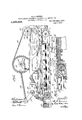
- Fig. 2 is a side elevation of the remainder of the machine containing particularly the pair of beaters and mechanism for delivering the finished or cleaned fiber from the machine, this figure being intended as a continuation of the front end of the machine shown in Fig. 1, so that when the two figures are placed end to end the entire machine is illustrated in side elevation;
- Fig. 3 is a. plan view of the front or feed end of the machine which is illustrated in Fig. 1;
- Fig. 4 is a sectional plan of the rear end of the machine, the section being taken on the line 44; of Fig. 2;
- Fig. 5 a. perspective view of.
- FIG. 6 a perspective view of a portion of one of the series of feed chains for feeding the straw transversely across the grid of the breaking mechanism;
- Fig. 7 a sectional plan on the line 77 of Fig. 1, and illustrating the grid, break chains, etc.;
- Fig. 8 a cross section on the line 8-8 of Fig. 7 butmade on a somewhat larger scale;
- Fig. 9 a detail view consisting of a section taken on the orcleaned fiber from the was held or clamped line 9-4) of Fig. 7;
- Fig. 10. is an enlarged sectional elevation on line 10 of Fig. 3;
- Fig. 11 is a view similar to Fig.
- Fig. 12 is a detail view of the rear endof the chains for conveying the material through the brake and front end of the scutching chain showing manner of delivery of the straw from one to the other;
- Fig. 13 a central vertical section taken on the line 1i313 of Fig. 4 and illustrating the scutching devices and the scutching chain;
- Fig. 14 a sectional plan, the section being taken on the line 14E1 l of Fig. 13;
- Fig. 15 an enlarged vertical section taken on line 15-15 of Fig. 4. illustrating the scutching devices and the manner of holding or clamping the straw while being acted upon by the beater and also illustrating the means for adjusting the scutching wheel;
- Fig. 12 is a detail view of the rear endof the chains for conveying the material through the brake and front end of the scutching chain showing manner of delivery of the straw from one to the other;
- Fig. 13 a central vertical section taken on the line 1i313 of Fig.
- FIG. 16 a similar view illustrating the other scutching board and beater;
- Fig. 17 a detail view of the shield arranged on the scutching board illustrated in Figs. 15 and 16;
- Fig. 18 a detail view showing the manner of delivery of the fiber to the delivery mechanism;
- Fig. 19 a detail view of the obliquely trending conveyer;
- Fig. 20 a detail view of its platform and clamping rib;
- Fig. 21 a detail view showing the manner of connection of the eccentric straps with the breaking blades;
- Fig. 22 a detail view of the means for adjusting or regulating the height of the grid and for permitting the rocking of the same.
- the same includes, in the order here named beginning at the left hand or feed end of the machine illustrated in Fig. 1, the conveying mechanism which receives the straw at the extreme left. hand end ofthe machine, the breaking mechanism whichbreaks the straw which is fed upon and across it by said conveying mechanism, the first clamping mechanism for clamping'the straw substantially at its middle and clamping it to the conveying mechaclamping nism or chain which carries it through the machine, the first beater which beats one end or substantially one half of the straw, the obliquely trending conveyer for moving the straw slightly longitudinally of its length, that is laterally of the machine at a gap'between the two heaters, the second device for clamping the straw at one side of its middle portion, the second beater for beating the other end of the straw, that is'the end not acted upon by the first beater, and finally the mechanism for delivering the finished or cleaned fiber from the machine, such latter mechanism being at the extreme right hand or delivery end of th machineas illustrated in
- the machine comprises a suitable frame indicated generally by 1 and of suitable size and length to accommodate or support the diflerent mechanisms now to be described.
- the breaking device or surface for breaking or crackling the straw the same consisting, as shown, of a grid, with which coiiperates a series of breaking blades or bars hereinafter more particularly described.
- the grid consists of a series of parallel bars 2 forming parallel spaces or interstices into which the movable breaking blades are depressed and into which they press the straw.
- This grid which, by preference, has a rocking or oscillating movement, is mounted upon and secured to the opposite sides of the machine frame. As shown more particularly in Fig. 8, the grid has a lower frame 2 which, by preference, is of I beam construction and an upper rectangular frame 2* in which the grid bars 2 are arranged in parallel relationship and connected together and positionedby means of cross bolts- 2 2.
- grid bars may be made of any suitable material and while metal may be employed, yet I have found in practice that wooden bars are more suitable and efficient, inasmuch as there is less possibility of any tearing action on the fibers of the straw.
- the entire grid structure is arranged to rock and accordingly the frame 2 while adapted to be supported at its ends alternately on the stationary cross pieces 1 of the machine frame is carried by and mounted to rock upon a cross shaft 3 which passes through the triangular supports or plates 3 at opposite sides of the grid frame and is journaled in the boxes 3 mounted loosely (to permit of a sliding movement) to the lower flanges of the two parallel longitudinal I beams on one side of the middle of the grid and toward thefront (Figs. 1, 10 and 22).
- cam plates are also pivoted at their lower endsupon the machine frame and provided with fingers or extensions 3 adapted to cooperate with notches on the edges of cam plates 1.
- Each cam plate is mounted in hearings on the main frame and provided with asquare end shaft whereby the same may be oscillated by a key wrench or the like. It will be apparent that the height of the grid is determined by the particular notches of the cam plates engaged by said finger. The purpose of the rocking of the grid will be explained when the operation of the machine is described.
- I provide a series of brake feed chains 7 which are preferably of the number and in the relationship in the grid as illustrated in Fig. 8, in which these chains are shown as also acting as breaking bars in the same manner as the regular bars of the grid.
- these feed chains are of such a size and are so positioned that the top of their links will be level with the upper edges of the regular grid bars, the teeth ofsuch links of course projecting thereabove for the purpose of feeding the straw, Fig. 8.
- feed loosely chains represent breaking bars and thereby serve the double function of feeding the straw and breaking or crackling the same in cooperation with the breaking blades.
- These feed'chains which are driven intermittently, extend over a series of sprocket wheels 8 mounted upon a driving shaft 9, Figs. 1, 7, termittently and in the manner and by the means hereinafter explained.
- these feed chains by preference extend around a common idler or cylinder 10, as shown in Figs. 7 and 10, the chains being properly spaced thereon in suitable manner, as by means of the series of rods 11, projecting from a fixed portion of the main frame.
- the feed chains are adapted to feed the straw in a direction longitudinal of the machine and from end to end of the grid and somewhat therebeyond until the same deliver the straw to a feed chain extending longitudinally of the machine and hereinafter referred to as the scutcher chain,
- breaking 10 and 11 which is operated in-- cam plates and plates are swung the grid in the operation of breaking or.
- breaking blades move repeatedly and rapidly and thereby impart rapid and successive impacts or blows upon the straw so conveyed unto the grid.
- breaking blades are provided at one end (in the present instance the front or feed end) with a raising and lowering device and at the other or delivery end with a raising and depressing device. As shown in Figs.
- the front ends of the blades are connected to a cross rod or shaft 17 which passes through them near their ends and which serves as a fulcrum therefor.
- This shaft and consequently the fulcrum is adapted to be raised and lowered, the same forming a part of the raising and lowering device above referred to.
- To thus change t-he'position of this shaft or fulcrum I provide a pair of cam plates 18, which are adapted to oscillate in time with the conveyer mechanism. These cam plates are provided with cam slots receiving the opposite ends of the shaft or fulcrum 17 and comprising two locking portions 19 and 20 which are concentric with the axis of the with an active portion 21. It will be understood that when the cam to the position illustrated in Figs.
- the front ends of the breaking blades are in theirlowermost position, inasmuch as their fulcrum occupies a position in the locking portion 19 of the cam slot which, though inactive as to vertical movement, yet holds the fulcrum in stationary position.
- the cam plates are oscillated in an anti-clockwise direction, theinclined portion 21' of the cam slot will raise the fulcrum 17 and such fulcrum will beheld in its elevated position by the portion 20 of the cam slot.
- 'lhese cam plates may be operated in any suitable manner, but in the present instance they are operated by the following driving connections:
- the cam plates are secured at their upper ends to a rock shaft 22 extending transversely of the machine and having bearings thereon at its ends.
- this shaft At one end of this shaft is secured a crank arm 23 pivotally connected at its outer end with a connecting rod 24 which in turn is pivot-ally connected to the large driving wheel 25, with the result that as such wheel is rotated .
- the cam plates 18 are oscillated as described.
- this wheel 25 is secured to one end of the shaft 26, to whose other end is secured a large sprocket wheel 27, which is driven through the medium of the sprocket chain 28 and sprocket wheel 29 by the driving or power pulley 30, connected with the latter.
- the so called raising and depressing device at the other or delivery end of the breaking blades comprises a series of eccentrics operatively connected with such blades for the purpose of raising and depressing the blades into freely the spaces or interstices between the bars of the grid.
- the eccentrics 31 are secured to a cross shaft 32 journaled onv the machine frame and rotated by the large driving wheel 25, through the medium of the sprocket chain 33 and sprocket Wheel 34".
- Each of these eccentrics has a strap 31* pivotally connected at its lower end to a pair of the breaking bladesthrough the medium of a plate 35, as shown in detail in Figs. 11 and 21.
- the series of eccentrics 31 are diderently timed and for this purpose the same are secured to their driving shaft 32 ocaaoa in difi'erent illustratedv in Fig. 3, with the result that in operation the eccentric at the center will opcrate first of all followed by the successive operations of the eccentrics on its opposite sides, a corresponding order of depression resulting in the driving or depressing of the breaking blades into the grid. ft is evident that when any one of the eccentrics is' in the position as illustrated in Fig. 10 the pair of breaking blades to which it .is connected will be in its depressed position and that when the eccentric is moved a half revolution, such blades will be in theirraised position.
- each of the breaking blades is a flat'strip of suitable material, such as metal and rectangular in shape, except as to the rear or delivery end, where the under edge of the same is cut away on a biasbeginning at the point 16 just inside the rear end of the grid. At this point, a restriction or throat is formed; The inclined or cut-away portions at the rear ends of these breaking relative positions, as clearly blades permit the free expansion and movement of the straw after it has passed through the restricted passage or throat just described.
- the break chains are operated intermittently in proper time with the movements of the breaking blades while the scutching chain is operated continuously.
- this intermittent movement of the conveyor chains is accomplished through the medium of driving connections with the large sprocket wheel 27.
- a connecting rod 36 is pivotally connected at its front end to a wrist pin 37, on said wheel and at its other end wlth a rock arm 38 which is fulcrumed at its lower end at 39. From a point intermedithe raising and lowering dethe upper end of connecting rod 40 which :is pivotally consaid shaft 9, with the result that as the drivb ing wheel 27 is rotated and the connecting rods are reciprocated, the ratchet wheel 18 advanced and. the break chains correspondingly advanced in the operation of feeding the straw longitudinally of the grid.
- :Ihe break chains are adapted to convey the straw across the grid longitudinally thereof and to deliver the same after being broken and crackled on the grid to the scutching chain, which carries it through the remainder'of the machine-in position to be acted upon by the scutching devices.
- I provide at a point in the rear of the grid and adjacent the series of sprocket chains 8,, a series .of strips or stripping fingers 44,Figs.
- each scutching wheel comprises a drum 45 to whose aperiphery is attached a series .of beater arms 46, Figs. 4, 13, 14, 15 and 16.
- the heater portions of these arms may be :an integral structure of any suitable material or, if desired, may be of metal provided with a facing 46' of a suitable material such-as wood, Figs. 15 and 16.
- beater portions rotate in a vertical plane while :the inner portions thereof are bent at right-angles andsecured
- I prefer to surround said drum and said inner ends of-the beater arm with a band 47, the parts being held together :by means of bolts 48, Fig. 15.
- These beater arms are adapted to rotate in close proxdelivered at a some 'imity to a scutching board arranged in a vertical ti plane and comprising an upper por on 49 and a lower portion 50, said rom by these fingers axis of the shaft 55.
- I is also a .disk and which scutching board is held in normal position I with a yielding pressure and to this end such brackets or rods 52 which pass loosely through a portion of the main frame 1 and are normally held upwardly with a yielding pressure by means of coiled springs 53,
- Each scutching wheel is adapted to be adjusted toward and away from its scutching board.
- the drum of the scutching wheel is secured to a shaft 55, on which is splined a driving wheel 56, maintained ⁇ in afixed position relative to the longitudinal axis of the shaft by means of the two distance sleeves 57 and 5-8 arranged on' either side thereof and encircling said shaft.
- This shaft 55 has its hearings in a supplemental frame 59 on themain frame and its outer therebeyond and isprovided with a collar 60 fixed thereto.
- This collar is engaged by and arranged to rotate in a block 61 which is adjustable in 'line with the longitudinal
- an adjusting screw 62 screwing through a bracket 63 and provided at its end with a hand wheel 64.
- This bracket is held pressed :toward the supplemental, frame coiled springs :65'exerting their tension outwardly against the ends of bolts 66 secured to said supplemental frame with the result that the heaters are adapted to yield outwardly. Itwill be understood that when the hand wheelx64 is moved in one direction or the other the entire shaft 55 and its scutching wheel is adjusted toward or away from its scutching board.
- Eachscutching wheel is provided with a shield 67 consist-mg of a flat disk covering or free end projects with a yielding pressure by means of the the inner face ofthe drum '45 andpreventmg the entrancethereinto of the straw. or,
- eachscutching wheel and its'board there is also provided in the present instance between eachscutching wheel and its'board a second or outer shield 68, which forms above the slot 51' a restricted space between itself and the scutching board in the neutral zone of two beating zones with a yielding pressure,
- this outer shield is spaced the proper distance from the scutching board by means of the plate 69, said plate and outer shield being secured to the lower portion of the scutching board in suitable manner.
- This outer shield is not essential.
- the object of the scutching board which is provided for each beater 0r scutching wheel is to hold the material, that is the straw or its hank, in proper position while being struck and scutched by the arms of the beater, such board serving to keep the material within the range, that is, within the path of rotation, of the beater arms.
- the scutching board extends across the entire face of its heater or scutching wheel and in fact extends therebeyond, are formed, one located below the plane of the scutching chain or the axis of rotation of the beater, and the other located thereabove, with an intermediate or neutral. zone located. at such axis of the beater or scutching wheel.
- the hank of straw or fiber is clamped to the scutching chain while being presented to the heaters or scutching wheels and to this end two clamping bars .70 and 71 are provided, both depending in thesame vertical plane and into the path of movement of the scutcher chain, Figs. 13, 15 and 16.
- These clamping bars are arranged to enter between the opposite sets of links or side plates forming part of the chain and t0 crimp the fiber therein and thereby hold the same from displacement while being acted upon by the heaters or scutching wheels.
- Each clamping bar vis similarly supported, the same being held downwardly in the present instance by springs 7 2 bearing at their lower ends against the heads of bolts 73, which are secured to the clamping bars and at their upper ends. against the angle plates 74, secured to the main frame 1. To adjust the tension of these springs, these angle plates are provided with adjusting screws 75.
- each of the clamping bars is upturned, the same being shoe-shaped, in order that the fiber which is being conveyed by the scutching chain will enter below the clamping bars and be clamped thereby to the chain.
- a long strip 76 which, in the present instance is square in cross section and fits within but does not entirely fill the depression, that is, it does not rise to the height of the side platescomprising a part of the links of the chain, as clearly shown in Figs. 15 and 16.
- This strip .or square bar is stationary, the same being secured at its forward end to a fixed part of the machine, as seen in Fig. 10 and extending upwardly and thence horizontally to the delivery end of the scutching chain.
- the chain itself as to its upper reach travels between said stri or bar 7 6 and a track 77 on the machine rame, Figs. 13 and 14.
- the rearward or delivery end of this stationary bar 76 is beveled so as to cooperate with the correspondingly beveled end of the stripping bar 78, (Fig. 18) which inclines upwardly and supports an apron 79, Fig. 4.
- the fiber being conveyed rearwardly by the scutching chain runs ofi from the stationary bar 76 it runs up upon the stripping bar 78, which elevates the same and removes it from the scutching chain, thereby brin -ng the same into the range of delivery mec anism.
- This mechanism in the present instance, comprises an endless conveyer or belt 80 run ning at its forward end over a pulley 81 and at its rearward end over the driving pulley 82.
- the lower reach of this belt is arranged in close proximity to the apron 79 and is adapted to engage the fiber which is stripped from the scutcher chain by the stripping bar and to convey the same rearwardly and deliver it therefrom.
- this delivery conveyer or belt is driven b the same connections that scutching chain and the delivery conveyer,
- a cross shaft 83 is journaled in the main frame toward the rearward end of the machine and provided on one end with a pulley 84 which is driven through of: shifting the 'the medium of a chain 94.
- the cross shaft 83 is provided with 'similar sprocket wheels 96, which serve to drive the sprocket wheels 56, before referred to, by
- the fiber or straw after being-presented to and acted uponby the forward beater or scutching wheel, must be moved or shifted laterally, that is to the right when the machine is viewed from the front or feed end, in order that the fiber or hank shall subsequently be gripped. or clamped at one point and that the point or portion theretofo-re clamped and only partially actedupon by the beater'shall be acted upon by the second or rearward beater while the right hand end of the fiber or hank is being beaten or scutched, with the result that the entire length of the fiber or hank is acted upon.
- the two clamping bars are separated a distance fromeach other so as to.provide a gap or an intervalof travel sufficient for the purpose fiber endwise, toward the right hand side of the machine, Fig. 4.
- the first clamping bar 70 therefore ends at or near the outward limit of movement of the forward beater'ar-ms and the upper section 49 of thescutching board for such beateris cut away at its rearward side at an angle extending upwardly and rearwardly in order to permit of sufficient space for the fiber or hank to expand and release itself from the space between the links of the scutcher chain, into which it has been 65. crimped by the clamping bar.
- obliquely trending conveying mechanism which, as'shown in detail in Figs. 4, '19 and 20, consists of an endless chain98, preferably having projecting teeth to engage the fiber, and positioned oblique with reference to the scutching chain which runs substantially centrally and longitudinally of the machine.
- This oblique conveyer being arranged on a plane above the scutching chain will now receive the fiber and gripping it between itself and a platform 99, will shift the same laterally a distance corresponding to the degree of obliquity of the chain.
- the fiber After traveling the distance of the gap between the clamping bars, the fiber is again delivered to the conveying action of the scutching chain and is also delivered. in position to be acted upon by the second clamping bar 71, whereby the,
- the chain 98 passes over pulleys 101 and 102, the latter of which is the driving pulley, Figs. 2, 4, and 19.
- This driving pulley is provided with a shaft 103 which is'connected by means of a universal joint 104 to a short driving shaft 105. This latter shaft is driven in suitable manner in unison with the scutcher chain and as shown in Fig.
- said shaft 105 is provided at its outer end with a sprocket wheel 106, which is driven through the medium of the sprocket chain 107 by means of a sprocket -By preference this platform 99' is provided wheel 108 secured to the same driving shaft 14 that serves to drive the scutching chain.
- the rear end of the sprocket chain 107 extends around a tightener sprocket wheel 109, and the lower reach of such chain extends over the top of the sprocket wheel 108 so as to give the oblique conveyer chain 98 the proper-direction of rotation.
- the wheel 109 is mounted on the side of an adjustable hand lever .110, which is pivoted at its lower end to the main frame and adapted to be held in adjusted position by a bolt 111 passing through a slot in a plate 112. It will be understood that as illustrated in Fig.
- this particular conveyer is arranged at or slightly above the horizontal plane of the scutching chain, which is the preferable construction, inasmuch as any tow or the like from the fiber is not liable to clog or interfere with the movements of the conveyer, inasmuch as the same would tend to drop by gravity through threshed or unthreshed) the machine and consequently away from such conveyer.
- the bearings for the sprockets 101 and 102 are mounted upon a frame 113, which is adapted to swing from a point 114 adjacent the bearing of the sprocket 101 as a center.
- any desired degree of obliquity may be secured and main-- tained for quently any desired amount of lateral shifting of the straw may be provided for.
- the straw Describing the operation of the machine by following the course of the material from its entrance as straw into the machine to its delivery as fiber therefrom, the straw (either is placed upon the feed table 118 at the front endof the machine (Figs. 1 and 3) and is fed by the operator, to the co-nveyer or feed chains in a layer or body and as uniformly as possible.
- the straw is now conveyed by the chains with an intermittent or step-by'step movement upon the grid, the operation of the parts being so timed that the forward movement for advancement of the straw takes place when the breaking blades are in their elevated position hereinbefo-re referred to.
- the breaking mechanism may be made other than as herein shown, yet the grid form is preferred inasmuch as it permits the wood or pith which have become detached to fall clear through the grid, thereby quickly disposing of the same and preventing it from following the straw in its further travel, even as far as the rearward end of the grid.
- the grid frame is mounted to rock and is also adjustable. This adjustment is provided in order that the proper working relationship between the grid and breaking blades may be obtained and the rocking thereof is provided particularly to relieve the machine of excessive strain in the breaking operation.
- the rear end of the grid which is in its upper position during the breaking operation, that is when the fulcrum shaft is down and held down thereby forcing the front end of the grid down, will be lowered when the breaking blades are raised and the break chains move with the result that with the same degree of rise of the lifting device at the front end of the machine a greater size of throat is provided at the rear end of the grid and an unimpeded passage provided for the fiber, thereby permitting free movement of such fiber and relieving the machine of strain.
- the straw becomes clamped toward its middle portion to the scutcher chain and. while so clamped is presented to and acted upon b the forward scutching wheel.
- the woo and pith which has been broken and loosened but not removed in the breaking operation is now scutched by the arnis of this beater, it being understood that, at this time, only theleft hand end portion of the fiber or bank is operated upon.
- the beating arms beat down upon the fiber, but after the center of the wheel is passed they beat up upon it, the wheels revolving in the direction indicated in the drawings by the arrows.
- both sides of the straw are beaten without any reversal of position of the hank, as is customary in hand scutching.
- the fiber is shifted, the same trending laterally to the right when viewed from the front end of the machine, so that the second clamping bar, to which the straw or hank is now presented in its further travel, will engage the hank on one side of its middle portion and on the scutched side, thereby presenting to the second or rearward scutching wheel the other or unscutched portion of the hank, as well as the middle portion which had been theretofore clamped by the bar 70.
- the scutcher chain is operated continuously, which is preferableto intermittent action, inasmuch as the continuous movement of this chain keeps the straw distributed uniformly throughout the machine, particularly as it takes the same fromthe break chains, thereby preventing the straw from becoming bunched together.
- the heaters are enabled to act upon the straw with increased effect.
- means for breaking the straw comprising a breaking surface, a series of blades adapted to cooperate with such surface and to strike the straw transversely, means for raising and lowering said series of blades after each complete series away from and toward an operative position with respect to said surface, and means for driving said blades successively against such surface after being so moved to operative position.
- means for breaking the straw comprising a. breaking surface, a series of blades adapted to cooperate with such surface and to strike the straw transversely, means for raising transversely,
- means for breaking the straw comprising a breaking surface, a series ofblades adapted to cooperate with such surface and to strike the straw transversely, means for raising and lowering said series of blades after each operation of the series away from and toward an operative position with respect to said surface, and means for swinging the blades successively.
- the means for breaking the straw comprisin a breaking surface, a plurality of blades adapted to cooperate with such surface and to strike the straw transversely, means connected with one end of said blades for raising and lowering them toward and away from an operative position with respect to said surface, and means connected with the other end thereof for depressing or driving said blades successively against such surface after being so moved to operative position.
- means for breaking the straw 'comprising a tent movement means for driving said blades against said surface, and means for lowering such blades to an operative position with respect to such surface preliminary to the said driving operation and for raising such blades during the forward movement of 5 the straw.
- means for breaking the straw comprising a breaking surface, a series of blades adapted to cooperate with such surface and to strike 1 the straw transversely, said blades being piv oted at one end, means for raising the' blades at the pivoted end, and means for swinging them about the pivot.
- 5 means for breaking the straw comprising a breaking surface, a series of bladesadapted to cooperate with such surface and to strike the straw transversely, said blades being pivoted at one end, means for raising the blades at the pivoted end, and means for separately and consecutively swingingthe blades to deliver blows upon the straw.
- the means for breaking the straw comprisin breaking surface, crumed at one end and adapted to co'ciperate with such surface and to strike the straw transversely, means'for raising and lowering the fulcrum of said blades, and meanscon nected with the other end of said'blades for depressingl and driving them successively t e breaking surface to break or crackle the-straw.
- the means for breaking the straw comprising a breaking surface, a plurality of blades fulcrumed at one end and adapted to cobp-c driving them against the.
- the means for breaking the straw compris-. mg a breaking surface, a plurality of blades adapted to cooperate with such surface and a to strike the straw transversely,
- a rod arranged at one end of said blades and actingas a fulcrum thereforfmeans for raisingand lowering said fulcrum, ,and'means co operating with the other end of said bladesfor depressing them toward the breaking surface to break the straw.
- the means for breaking the straw comprising a breaking surface, a plurality adapted to cciiperate with such surface and to strike the straw transversely, meanscooperatmg with the front ends of said blades for-raising and lowering them thereat and for locking them in working position, and means-cotiperating with the other ends of said blades for depressing them against the v breaking surface.
- the means for breaking the straw comprismg a breaking surface, a'plurality of blades adapted to coiiperate with such-surface and tostrike the straw transversely, and-separate means cotiperating with theends'of said blades for depressing thenr unequal amounts, one end being loweredor depressed to a working position and the'o'ther end bemg further lowered and driven against the breaking surface to break the straw.
- the means for breaking the straw comprismg a breaking surface, a plurality ofblades adapted to cotiperate end of said blades for award the breaking surface. a plurality of blades ulto strike ranged at one, end of said blades and acting of blades vmeans.icopcrating with said blades ing and lowering one end;
- the means for breaking the straw comprising a breaking surface, a plurality of blades adapted to cotiperate with such surface and the straw transversely, a rod aras a fulcrum therefor, cam mechanism cooperating with said rod for raising and lowering the same together with the blades, and means cot'vperating with the other end of said blades for depressing them toward the breaking surface.
- the means for breaking he straw comprising to strike the straw transversely, a rod or shaft arranged at one end of said blades and acting as a, fulcrum -tl1erefor, cam mechanism for raising and lowering said rod'consisting of a pair of plates having cam slots receiving the ends of said shaft, and means for oscillating said plates, and means cotiperating with theother end of said blades for depressing'them toward the breaking surfaces r I 17
- the means for braking the straw comprising a breaking surface, a plurality of blades adapted to coiiperat'e with such surface and transversely, a rod or of said blades and crum therefor, cam mechasisting of a pair of plates having cam slots receiymg the ends of said shaft, saidslots having an angular and a concentric portion,
- the means for breaking the straw comprising a breaking surface, a plurality of blades adapted to cooperate with such surface and to strike the straw transversely, means'for raising-and lowering one end of said blades before each operation of the series of blades, a series of eccentric straps connected to the other end of said blades, and differently timed eccentrics for such straps.
- the means for breaking the straw comprising a breaking surface, aplurality of blades adapted to cooperatefwith such surface and to strike the straw transversely, means for raising and lowering one end of said blades, a series of eccentric straps connectedto the other end of said blades in pairs, one strap to two blades, and differently timed eccentrics for such straps.
- the means for breaking the straw comprising a grid consisting of a series of parallel bars, a plurality of blades arranged above the grid in alinement, with the spaces between said bars, means for raising and lowering said blades before each operation of the series of blades toward and away from an operative position with respect to said surface, and means for driving said blades successively between said bars after being so moved to operative position.
- the means for breaking comprising a breaking surface, aplurality of blades adapted to cooperate with such surface and to strike the straw transversely, means for raising and lowering said blades toward and away from an operativeposition with respect to said surface, means for driving said blades successively against such surface, and means. for advancing the straw across the breaking surface during the interval when the blades are raised.
- the means for breaking the straw comprising a breaking surface, a plurality of blades adapted to cooperate with such surface and to strike the straw transversely, means for raising and lowering said blades toward and away from an operative position with respect to said surface, means for driving said blades successively against such surface, and conveyer mechanism intermittently operated .and adapted to convey the straw across the breaking surface during the interval when the blades are raised.
- the means for breaking the straw comprising a breaking surface, a plurality of blades adapted to cooperate with such surface and to strike thestraw transversely, meansfor raising and lowering said blades toward and away from an -operative position with respect to said surface, means for driving said blades successively against such surface, and
- a series of chains for conveying the straw across the breaking surface and sunk theretl1e combination of a adapted to cooperate with such surface and to strike the straw transversely, means for raising and lowering said blades toward and away from an operative position with respect to said surface, means for driving said 'blades successively against such surface after being so moved to operative position, and a series of break chains provided with teeth for engaging and conveying the straw across-the breaking surface, 'said chains being sunk in the breaking surface to form a part thereof in the operation of the blades, the upper face of said breaking surface being substantially flush except for said projecting teeth.
- the combination with a main frame, of a series of breaking blades, a pivoted breaking surface with which said blades cooperate, said breaking surface comprising a frame and a series of parallel bars forming a grid, and means for adjusting the height of the breaking surface with respect to the breaking blades.
Landscapes
- Engineering & Computer Science (AREA)
- Mechanical Engineering (AREA)
- Textile Engineering (AREA)
- Preliminary Treatment Of Fibers (AREA)
Description
B. S. SUMMERS.
MECHANISM FOR TREATING THE sTR-AW 0F PLAX AND THE LIKE;
7 APPLICATION FILED MAB..11, 1908. 1,069,202. Patented Aug. 5, 1913.
9 SHEETSSHEET 1.
B. s. SUMMERS. MECHANISM FOR TREATING THE STRAW OP FLAX AND THE LIKE.
' APPLIOATION FILED MAR.11, 1908. I
Patented Aug. 5, 1913.
-9 SHEETS-SHEET 2.
fgzz' B. S. SUMMERS.
MECHANISM FOR TREATING THE STRAW OF FLAX AND THE LIKE,
APPLICATION FILED MAR.11,1908.
1,069,202. Patented Aug. 5, 1913.
9 SHEETS-SHEET 3.
B. S. SUMMERS. MECHANISM FOR TREATING. THE STRAW OF FLAX AND THE LIKE.
APPLICATION FILED MAR.11,1908.
1,069,202. v Patented Aug. 5, 1913.
9 SHEETS-SHEET 4.
B. s. SUMMERS. MECHANISM FOR TREATING THE STRAW 0F FLAX AND THE LIKE.
APPLICATION FILED MAE. 11,1908- 1,069,202. Patented Aug. 5, 1913.
9 SHEETE-SHEET 5 K9 7 i m i B. S. SUMMERS. MECHANISM FOR TREATING THE STRAW 0F FLAX AND'THE LIKE.
Patented Aug. 5, 1913.
' 9 SHEETS-SHEBT 6.
llllIlII APPLICATION FILED MAB. 11,1908. I 1,069,202.
B. S. SUMMERS. MECHANISM FOR TREATING THE STRAW 0F FLAX AND.THB LIKE.
APPLICATION TILED MA'R.11,1908.
- Patented Aug. 5, 1913.
B. S. SUMMERS. MECHANISM FOR TREATING THE STRAW 0E FLAX AND THE LIKE.
9 SHEETS-SHEET 8.
Patented Aug. 5, 1913.
IIIIIIII IIII I l l l l I l ll ll l 1 APPLIDATION FILED MAB-11,1908. 1,069,202.
B. s. SUMMERS.
' MECHANISM FOR TREATING THE STRAW 0F PLAX AND THE LIKE. v 1,069,202. Patented Aug. 5, 1913.
. 9 SHEETS-SHEET 9.
APPLICATION FILED MAR.11,1908.
UNITED STATES PATENT oFFIoE.
BERTRAND s. sUMMEns'or PORT-HURON, MICHIGAN, ASSIGNOR TO SUMMERS LINEN COMPANY, A ooR oRATIoN or MAINE.
MECHANISM FOR TREATING THE STRAW OF FLAX AND THE LIKE.
Specification of Letters Patent.
Patented Aug. 5,1913.
Application filed March 11, 1908. Serial No. 420,431.
To all whom it may concern:
Be it known that I, BERTRAND S. SUM- MERS, a citizen of the United States, residing at Port Huron, in the county of St. Clair and State of Michigan, have invented a certain new and useful Mechanism for Treat-ing the Straw of Flax and the Like, of which the following is a specification.
My invention relates to the art of treating the straw of flax and the like for the production of fiber and the object thereof is to provide a simple, reliable and etficient machine for accomplishing this result in a continuous, expeditious and satisfactory manner. To this end I provide a machine having a novel construction and mode of operation,
I for breaking the straw throughout its length,
thereby breaking or cracklingthe wood or pi-th thereof, and then for scutching or heating the straw to free the fiber from such wood or pith, the operation being automatic and continuous from the feeding of the straw at one end of the machine to its delivery as cleaned fiber at the other end thereof. In the present instance the mechanism forbreaking the straw comprises a breaking surface in the form of a grid and a series of breaking blades or bars capable of imparting repeated and successive impacts or blows upon the straw from the middle outwardly, with the result that portions of the straw are forced by such blades into the spaces of the grid andthereby sharply bent or crimped, said successive action so imposed upon the straw from the middle outwardly to the ends providing the required slack to form the bends or crimps by the free inward longitudinal motion of that portion of the straw not yet acted upon by the breaking bars, so that the wood or pith. is broken without breaking or afi'ecting the strength of the fiber itself in any manner. The heating or sciitching mechanism comprises a. pair of scutching wheels,
adapted in cooperation with scutching boards to thoroughly beat and clean the material or hank on both sides or in both directions, first beating the same downwardly as it approaches the center of the wheel and then upwardly as it recedes therefrom, with the result that the wood and pith loosened in the breaking operation and not removed at that point are efi'ectually removed, leaving the fibers intact and clean.
My machine is automatic in its operation, from the feeding of the straw at one end of the machine to the delivery thereof at the opposite end, such result being accomplished by mechanism for conveying the straw through the machine and past the agencies or operating devices described and also by mechanism for conveying. and deliv-v ering the finished machine.
My machine employs 'as an additional feature novel and efficient mechanism for conveying the straw lengthwise, that is obliquely of the length of the machine, at a point in its travel between the beater, so that the straw may be efficiently: beaten throughoutits entire length, that portion of the straw whicl when acted upon by the first beater being thereupon made subject to the act-ion of the second beater, and consequently properly beaten and cleane My invention embodies other novel and advantageous features of construction and mode of operationwhich will be apparent from the description hereinafter given.
In the drawings, Figure 1 is a side elevation of one end of the machine, the same being the receiving or feed end containing particularly the mechanism for breaking or crackling the straw; Fig. 2 is a side elevation of the remainder of the machine containing particularly the pair of beaters and mechanism for delivering the finished or cleaned fiber from the machine, this figure being intended as a continuation of the front end of the machine shown in Fig. 1, so that when the two figures are placed end to end the entire machine is illustrated in side elevation; Fig. 3 is a. plan view of the front or feed end of the machine which is illustrated in Fig. 1; Fig. 4 is a sectional plan of the rear end of the machine, the section being taken on the line 44; of Fig. 2; Fig. 5 a. perspective view of. a portion of the scutc ing chain which serves to feed the straw through the scutching machine;'Fig. 6 a perspective view of a portion of one of the series of feed chains for feeding the straw transversely across the grid of the breaking mechanism; Fig. 7 a sectional plan on the line 77 of Fig. 1, and illustrating the grid, break chains, etc.; Fig. 8 a cross section on the line 8-8 of Fig. 7 butmade on a somewhat larger scale; Fig. 9 a detail view consisting of a section taken on the orcleaned fiber from the was held or clamped line 9-4) of Fig. 7; Fig. 10. is an enlarged sectional elevation on line 10 of Fig. 3; Fig. 11 is a view similar to Fig. 10 but illustrating the breaking blades in their elevated position; Fig. 12 is a detail view of the rear endof the chains for conveying the material through the brake and front end of the scutching chain showing manner of delivery of the straw from one to the other; Fig. 13 a central vertical section taken on the line 1i313 of Fig. 4 and illustrating the scutching devices and the scutching chain; Fig. 14 a sectional plan, the section being taken on the line 14E1 l of Fig. 13; Fig. 15 an enlarged vertical section taken on line 15-15 of Fig. 4. illustrating the scutching devices and the manner of holding or clamping the straw while being acted upon by the beater and also illustrating the means for adjusting the scutching wheel; Fig. 16 a similar view illustrating the other scutching board and beater; Fig. 17 a detail view of the shield arranged on the scutching board illustrated in Figs. 15 and 16; Fig. 18 a detail view showing the manner of delivery of the fiber to the delivery mechanism; Fig. 19 a detail view of the obliquely trending conveyer; Fig. 20 a detail view of its platform and clamping rib; Fig. 21 a detail view showing the manner of connection of the eccentric straps with the breaking blades; and Fig. 22 a detail view of the means for adjusting or regulating the height of the grid and for permitting the rocking of the same.
Referring to the embodiment of my machine as herein shown, the same includes, in the order here named beginning at the left hand or feed end of the machine illustrated in Fig. 1, the conveying mechanism which receives the straw at the extreme left. hand end ofthe machine, the breaking mechanism whichbreaks the straw which is fed upon and across it by said conveying mechanism, the first clamping mechanism for clamping'the straw substantially at its middle and clamping it to the conveying mechaclamping nism or chain which carries it through the machine, the first beater which beats one end or substantially one half of the straw, the obliquely trending conveyer for moving the straw slightly longitudinally of its length, that is laterally of the machine at a gap'between the two heaters, the second device for clamping the straw at one side of its middle portion, the second beater for beating the other end of the straw, that is'the end not acted upon by the first beater, and finally the mechanism for delivering the finished or cleaned fiber from the machine, such latter mechanism being at the extreme right hand or delivery end of th machineas illustrated in Fig. 2. r
The machine comprises a suitable frame indicated generally by 1 and of suitable size and length to accommodate or support the diflerent mechanisms now to be described. Near the left hand or feed end (Fig. 1) is arranged the breaking device or surface for breaking or crackling the straw, the same consisting, as shown, of a grid, with which coiiperates a series of breaking blades or bars hereinafter more particularly described. As shown more clearly in Figs. 7 and 8, the grid consists of a series of parallel bars 2 forming parallel spaces or interstices into which the movable breaking blades are depressed and into which they press the straw. While other forms of breaking surfaces may be employed, I prefer the form described, inasmuch as, being open from top to bottom, the same permits the woody particles and chaff of the straw to fall therethrough and to thereby clear themselves from the fiber which is to be passed farther through the machine. This grid, which, by preference, has a rocking or oscillating movement, is mounted upon and secured to the opposite sides of the machine frame. As shown more particularly in Fig. 8, the grid has a lower frame 2 which, by preference, is of I beam construction and an upper rectangular frame 2* in which the grid bars 2 are arranged in parallel relationship and connected together and positionedby means of cross bolts- 2 2. These grid bars may be made of any suitable material and while metal may be employed, yet I have found in practice that wooden bars are more suitable and efficient, inasmuch as there is less possibility of any tearing action on the fibers of the straw. The entire grid structure is arranged to rock and accordingly the frame 2 while adapted to be supported at its ends alternately on the stationary cross pieces 1 of the machine frame is carried by and mounted to rock upon a cross shaft 3 which passes through the triangular supports or plates 3 at opposite sides of the grid frame and is journaled in the boxes 3 mounted loosely (to permit of a sliding movement) to the lower flanges of the two parallel longitudinal I beams on one side of the middle of the grid and toward thefront (Figs. 1, 10 and 22). These plates are also pivoted at their lower endsupon the machine frame and provided with fingers or extensions 3 adapted to cooperate with notches on the edges of cam plates 1. Each cam plate is mounted in hearings on the main frame and provided with asquare end shaft whereby the same may be oscillated by a key wrench or the like. It will be apparent that the height of the grid is determined by the particular notches of the cam plates engaged by said finger. The purpose of the rocking of the grid will be explained when the operation of the machine is described. Near each end of the I beam frame of the grid is a shaft 5 passing therethlough and provided with collars 5 to prevent the shaft from moving sidewise. The ends of these shafts project into the slots 6" of plates or castings 6, which slots extend vertically a suflicient distance and are a trifle wider than the shaft diameter (Figs. 8 and 22). By this arrangement the shafts are permitted to move in the rocking action of the grid and are moreover guided in said movements.
F or conveying or feeding the straw across and longitudinally of the machine with an intermittent movement, I provide a series of brake feed chains 7 which are preferably of the number and in the relationship in the grid as illustrated in Fig. 8, in which these chains are shown as also acting as breaking bars in the same manner as the regular bars of the grid. To this end, at the points where the feed chains travel the regular grid bars are omitted and strips 2 are inserted for the chain to run upon. These feed chains are of such a size and are so positioned that the top of their links will be level with the upper edges of the regular grid bars, the teeth ofsuch links of course projecting thereabove for the purpose of feeding the straw, Fig. 8. As a result of this construction and arrangement, it is evident that these feed loosely chains represent breaking bars and thereby serve the double function of feeding the straw and breaking or crackling the same in cooperation with the breaking blades. These feed'chains, which are driven intermittently, extend over a series of sprocket wheels 8 mounted upon a driving shaft 9, Figs. 1, 7, termittently and in the manner and by the means hereinafter explained. At their other ends, these feed chains by preference extend around a common idler or cylinder 10, as shown in Figs. 7 and 10, the chains being properly spaced thereon in suitable manner, as by means of the series of rods 11, projecting from a fixed portion of the main frame. The feed chains are adapted to feed the straw in a direction longitudinal of the machine and from end to end of the grid and somewhat therebeyond until the same deliver the straw to a feed chain extending longitudinally of the machine and hereinafter referred to as the scutcher chain,
which feeds the straw past the beaters and At its forward end this scutcher chain ex tends over an idler pulley 15, which is mounted upon the cross shaft 9,
Fig. 12.
These breaking 10 and 11, which is operated in-- cam plates and plates are swung the grid in the operation of breaking or.
rather crimping the straw, thereby crackling and loosening the wood thereof, are represented by the series of blades 16, riveted together in pairs with suitable spaces between and equaling in number the spaces or interstices between the grid bars, including the chains hereinbefore referred to as serving as grid bars,Fig. 8. As the straw is fed over the grid by th se feed chains, the breaking blades are operated at the proper time and forced downwardly in said interstices of the grid, thereby striking and thrusting the straw therein and crimping the same with the results already specified. blades'are not operated or depressed simultaneously, but the construction and arrangement of the operating mechanism therefor is such that the blades at the center are first depressed and then the remainder are depressed successively,
the action being progressively from the center outwardly to the opposite sides, with the result that in the crimping of the straw suflicient slack is provided in order ,to make the crimps without breaking, tearing or straining the fiber of the straw. These breaking blades move repeatedly and rapidly and thereby impart rapid and successive impacts or blows upon the straw so conveyed unto the grid. -For the purpose of operating these breaking blades in the peculiar manner just described, such blades are provided at one end (in the present instance the front or feed end) with a raising and lowering device and at the other or delivery end with a raising and depressing device. As shown in Figs. 1, 10 and 11, the front ends of the blades are connected to a cross rod or shaft 17 which passes through them near their ends and which serves as a fulcrum therefor. This shaft and consequently the fulcrum is adapted to be raised and lowered, the same forming a part of the raising and lowering device above referred to. To thus change t-he'position of this shaft or fulcrum I provide a pair of cam plates 18, which are adapted to oscillate in time with the conveyer mechanism. These cam plates are provided with cam slots receiving the opposite ends of the shaft or fulcrum 17 and comprising two locking portions 19 and 20 which are concentric with the axis of the with an active portion 21. It will be understood that when the cam to the position illustrated in Figs. 1 and 10, the front ends of the breaking blades are in theirlowermost position, inasmuch as their fulcrum occupies a position in the locking portion 19 of the cam slot which, though inactive as to vertical movement, yet holds the fulcrum in stationary position. When, however, the cam plates are oscillated in an anti-clockwise direction, theinclined portion 21' of the cam slot will raise the fulcrum 17 and such fulcrum will beheld in its elevated position by the portion 20 of the cam slot. 'lhese cam plates may be operated in any suitable manner, but in the present instance they are operated by the following driving connections: The cam plates are secured at their upper ends to a rock shaft 22 extending transversely of the machine and having bearings thereon at its ends. At one end of this shaft is secured a crank arm 23 pivotally connected at its outer end with a connecting rod 24 which in turn is pivot-ally connected to the large driving wheel 25, with the result that as such wheel is rotated .the cam plates 18 are oscillated as described. As shown, this wheel 25 is secured to one end of the shaft 26, to whose other end is secured a large sprocket wheel 27, which is driven through the medium of the sprocket chain 28 and sprocket wheel 29 by the driving or power pulley 30, connected with the latter. It will be understood that the movement of these driving connections is continuous, but the raising and lowering of the fulcrum 17 of the break ing blades is intermittent, inasmuch as the port- ions 19 and 20 of the cam plates are of such length as to hold such fulcrum the required length of time in both its raised and lowered positions. Moreover, the movements of the fulcrum as thus 'causedby the cam plates, is so timed that the fulcrum is raised during the time that the intermittently operating conveyer chains are in motion, so that the straw will be fed forward andwithout interference from the breaking blades. In order to maintain the fulcrum shaft 17 in proper position and prevent endwise movement thereof, 1 provide distance rods 17 the forward ends of which are pivoted to said shaft and the rearward ends of which are pivoted to the machine frame (Figs. 1, 10 and 11).
Referring next to the so called raising and depressing device at the other or delivery end of the breaking blades, the same comprises a series of eccentrics operatively connected with such blades for the purpose of raising and depressing the blades into freely the spaces or interstices between the bars of the grid. As shown, particularly in Figs. 3 and 10, the eccentrics 31 are secured to a cross shaft 32 journaled onv the machine frame and rotated by the large driving wheel 25, through the medium of the sprocket chain 33 and sprocket Wheel 34".- Each of these eccentrics has a strap 31* pivotally connected at its lower end to a pair of the breaking bladesthrough the medium of a plate 35, as shown in detail in Figs. 11 and 21. The series of eccentrics 31 are diderently timed and for this purpose the same are secured to their driving shaft 32 ocaaoa in difi'erent illustratedv in Fig. 3, with the result that in operation the eccentric at the center will opcrate first of all followed by the successive operations of the eccentrics on its opposite sides, a corresponding order of depression resulting in the driving or depressing of the breaking blades into the grid. ft is evident that when any one of the eccentrics is' in the position as illustrated in Fig. 10 the pair of breaking blades to which it .is connected will be in its depressed position and that when the eccentric is moved a half revolution, such blades will be in theirraised position.
As illustrated more clearly in Fig. 10, each of the breaking blades is a flat'strip of suitable material, such as metal and rectangular in shape, except as to the rear or delivery end, where the under edge of the same is cut away on a biasbeginning at the point 16 just inside the rear end of the grid. At this point, a restriction or throat is formed; The inclined or cut-away portions at the rear ends of these breaking relative positions, as clearly blades permit the free expansion and movement of the straw after it has passed through the restricted passage or throat just described. This restricted passage or throat arises from the fact-that the opening of the breaking device for the free passage of the fiber, when the conveyor chains move, is provided by vice and the motion of this device must be sufficient to permit the fiber to move freely at this point whether the eccentrics are in their lowest position or not. In view of the functions performed by the diflerent operating mechanisms at the opposite ends of the breaking blades, I term the mechanism or device at the front or feed end of the blades a raising and lowering device, inasmuch as it raises the pivoted end of the blade simultaneously, and lowers them simultaneously. The operating mechanism at the other end of the blades, 1 term the raising and depressing device, inasmuch as the same raises and lowers the blades separately and at different times and also depresses them into the breaking surface or grid.
As hereinbefore stated, the break chains are operated intermittently in proper time with the movements of the breaking blades while the scutching chain is operated continuously. In the present instance, this intermittent movement of the conveyor chains is accomplished through the medium of driving connections with the large sprocket wheel 27. As shown in Figs. 1 and 2, a connecting rod 36 is pivotally connected at its front end to a wrist pin 37, on said wheel and at its other end wlth a rock arm 38 which is fulcrumed at its lower end at 39. From a point intermedithe raising and lowering dethe upper end of connecting rod 40 which :is pivotally consaid shaft 9, with the result that as the drivb ing wheel 27 is rotated and the connecting rods are reciprocated, the ratchet wheel 18 advanced and. the break chains correspondingly advanced in the operation of feeding the straw longitudinally of the grid.
:Ihe break chains are adapted to convey the straw across the grid longitudinally thereof and to deliver the same after being broken and crackled on the grid to the scutching chain, which carries it through the remainder'of the machine-in position to be acted upon by the scutching devices. In order to properly and effectually deliver the straw or fiber from the break chains :to the scutching chains, I provide at a point in the rear of the grid and adjacent the series of sprocket chains 8,, a series .of strips or stripping fingers 44,Figs. 7 and 10, which are inclined upwardly from the rear end of the grid and .extend to a point beyond or in the rear of said sprocket wheels, so that the straw being carried u on the break chains will be stripped theref and will thereupon be what higher plane .to the scutching chain, which will thereupon engage the same and carry it rearwardly through the machine.
Referring next to the mechanism for scutching or beating the straw, I provide the machine with two beaters or scutching wheels rotating in separate planes extending longitudinally of the machine and adapted to operate separately upon the straw which is fed through the machine and to the beaters and from one beater to the other by means of the scutcher chain before referred to. In the present embodiment of my invention, each scutching wheel comprises a drum 45 to whose aperiphery is attached a series .of beater arms 46, Figs. 4, 13, 14, 15 and 16. The heater portions of these arms may be :an integral structure of any suitable material or, if desired, may be of metal provided with a facing 46' of a suitable material such-as wood, Figs. 15 and 16. These beater portions rotate in a vertical plane while :the inner portions thereof are bent at right-angles andsecured cesses in the practice, I, prefer to surround said drum and said inner ends of-the beater arm with a band 47, the parts being held together :by means of bolts 48, Fig. 15. These beater arms are adapted to rotate in close proxdelivered at a some 'imity to a scutching board arranged in a vertical ti plane and comprising an upper por on 49 and a lower portion 50, said rom by these fingers axis of the shaft 55.
to re-- periphery of .said drum. In
I is also a .disk and which scutching board is held in normal position I with a yielding pressure and to this end such brackets or rods 52 which pass loosely through a portion of the main frame 1 and are normally held upwardly with a yielding pressure by means of coiled springs 53,
which bear respectively against the main frame and against collars 54 at the ends of the rods, as .clearly illustrated in F ig.13. By reason of the yielding mounting of the upper portion of such board it is held in oard is supported in position by means of close proximity to the lower section of the 1 board whereby the opening between the two is kept as narrow as possible and at the same-time it yields to prevent choking in case the straw is unduly crowded between the sections of the board.
Each scutching wheel is adapted to be adjusted toward and away from its scutching board. Referring to the construction as shown herein in Figs. 4 and 15, the drum of the scutching wheel is secured to a shaft 55, on which is splined a driving wheel 56, maintained {in afixed position relative to the longitudinal axis of the shaft by means of the two distance sleeves 57 and 5-8 arranged on' either side thereof and encircling said shaft. This shaft 55 has its hearings in a supplemental frame 59 on themain frame and its outer therebeyond and isprovided with a collar 60 fixed thereto. This collar is engaged by and arranged to rotate in a block 61 which is adjustable in 'line with the longitudinal To this casing is secured an adjusting screw 62, screwing through a bracket 63 and provided at its end witha hand wheel 64. This bracket is held pressed :toward the supplemental, frame coiled springs :65'exerting their tension outwardly against the ends of bolts 66 secured to said supplemental frame with the result that the heaters are adapted to yield outwardly. Itwill be understood that when the hand wheelx64 is moved in one direction or the other the entire shaft 55 and its scutching wheel is adjusted toward or away from its scutching board.
Eachscutching wheel is provided with a shield 67 consist-mg of a flat disk covering or free end projects with a yielding pressure by means of the the inner face ofthe drum '45 andpreventmg the entrancethereinto of the straw. or,
fiber.- There is also provided in the present instance between eachscutching wheel and its'board a second or outer shield 68, which forms above the slot 51' a restricted space between itself and the scutching board in the neutral zone of two beating zones with a yielding pressure,
the scutching the straw or fiber passing therethrough, after being acted upon in one direction by the beater arms at one side of the wheel and before being acted upon by the beater arms at the other side of the wheels, isprevented from twisting or'roping, and thereby held in proper straight condition for action by. the other set of beater arms. As shown, this outer shield is spaced the proper distance from the scutching board by means of the plate 69, said plate and outer shield being secured to the lower portion of the scutching board in suitable manner. This outer shield, however, is not essential.
The object of the scutching board which is provided for each beater 0r scutching wheel is to hold the material, that is the straw or its hank, in proper position while being struck and scutched by the arms of the beater, such board serving to keep the material within the range, that is, within the path of rotation, of the beater arms. Inasmuch as the scutching board extends across the entire face of its heater or scutching wheel and in fact extends therebeyond, are formed, one located below the plane of the scutching chain or the axis of rotation of the beater, and the other located thereabove, with an intermediate or neutral. zone located. at such axis of the beater or scutching wheel. It is therefore evident that the straw or hank is scutched both from above and from below, while the provision of the neutral zone, permits the hank to change its position so as to be acted upon in the opposite directions from that oecurring during the first scutching action of the heater? or scutching wheel.
The hank of straw or fiber is clamped to the scutching chain while being presented to the heaters or scutching wheels and to this end two clamping bars .70 and 71 are provided, both depending in thesame vertical plane and into the path of movement of the scutcher chain, Figs. 13, 15 and 16. These clamping bars are arranged to enter between the opposite sets of links or side plates forming part of the chain and t0 crimp the fiber therein and thereby hold the same from displacement while being acted upon by the heaters or scutching wheels. Each clamping bar vis similarly supported, the same being held downwardly in the present instance by springs 7 2 bearing at their lower ends against the heads of bolts 73, which are secured to the clamping bars and at their upper ends. against the angle plates 74, secured to the main frame 1. To adjust the tension of these springs, these angle plates are provided with adjusting screws 75. By
these means, the normal position of the clamping bars with respect to the scutcher wheel, with the resultthati as:
,chain is adjusted and the degree of tension imparted is regulated. The forward end of each of the clamping bars is upturned, the same being shoe-shaped, in order that the fiber which is being conveyed by the scutching chain will enter below the clamping bars and be clamped thereby to the chain.
In order that an unbroken surface may be presented to the fiber as it is pressed or crimped into the depressions between the side plates of the scutching chain, which surface is not found in the chain itself owing to the spaces between the links, 1 arrange within such depressions a long strip 76 which, in the present instance is square in cross section and fits within but does not entirely fill the depression, that is, it does not rise to the height of the side platescomprising a part of the links of the chain, as clearly shown in Figs. 15 and 16. This strip .or square bar is stationary, the same being secured at its forward end to a fixed part of the machine, as seen in Fig. 10 and extending upwardly and thence horizontally to the delivery end of the scutching chain. The chain itself, as to its upper reach travels between said stri or bar 7 6 and a track 77 on the machine rame, Figs. 13 and 14. As illustrated, the rearward or delivery end of this stationary bar 76 is beveled so as to cooperate with the correspondingly beveled end of the stripping bar 78, (Fig. 18) which inclines upwardly and supports an apron 79, Fig. 4. As the fiber being conveyed rearwardly by the scutching chain runs ofi from the stationary bar 76 it runs up upon the stripping bar 78, which elevates the same and removes it from the scutching chain, thereby brin -ng the same into the range of delivery mec anism. This mechanism, in the present instance, comprises an endless conveyer or belt 80 run ning at its forward end over a pulley 81 and at its rearward end over the driving pulley 82. The lower reach of this belt is arranged in close proximity to the apron 79 and is adapted to engage the fiber which is stripped from the scutcher chain by the stripping bar and to convey the same rearwardly and deliver it therefrom. In the present instance this delivery conveyer or belt is driven b the same connections that scutching chain and the delivery conveyer,
which driving connections will now be de scribed: A cross shaft 83 is journaled in the main frame toward the rearward end of the machine and provided on one end with a pulley 84 which is driven through of: shifting the 'the medium of a chain 94.
the medium of a belt 85 and a pulley mounted on the same power shaft30 as the main driving pulley 30 (Figs. 2, 3 and in-adjustable bearing boxes 90*,Fig. 2, and
the same is provided with a pinion 91 which meshes with a gear wheel 14 mounted on the' shaft 14. that drives the scutcherchain. This shaft is made vertically adjustable for the purpose "of. permitting different sizes of gear wheels or pinions to be used to ob tam different speeds of the scutcher chain to thereby vary the duration ofthe action of the beaters upon the straw. I
Referring next tothe driving connections for' the delivery conveyer, a. sprocket wheel 92 1s secured to the shaft 90 and adapted to drive the large sprocket wheel 93 through This wheel 93 is mounted on the same shaft 95 on which the pulley 82 is mounted and consequently the delivery conveyer or belt which runs over sald pulley is operated by the rotation of the sha t 90. Now referring to the driving connections for the scutching wheels, the cross shaft 83 is provided with 'similar sprocket wheels 96, which serve to drive the sprocket wheels 56, before referred to, by
. means of the sprocket chains 97;
The fiber or straw after being-presented to and acted uponby the forward beater or scutching wheel, must be moved or shifted laterally, that is to the right when the machine is viewed from the front or feed end, in order that the fiber or hank shall subsequently be gripped. or clamped at one point and that the point or portion theretofo-re clamped and only partially actedupon by the beater'shall be acted upon by the second or rearward beater while the right hand end of the fiber or hank is being beaten or scutched, with the result that the entire length of the fiber or hank is acted upon. In order to accomplish this result, the two clamping bars are separated a distance fromeach other so as to.provide a gap or an intervalof travel sufficient for the purpose fiber endwise, toward the right hand side of the machine, Fig. 4. The first clamping bar 70 therefore ends at or near the outward limit of movement of the forward beater'ar-ms and the upper section 49 of thescutching board for such beateris cut away at its rearward side at an angle extending upwardly and rearwardly in order to permit of sufficient space for the fiber or hank to expand and release itself from the space between the links of the scutcher chain, into which it has been 65. crimped by the clamping bar. The straw is now presented to an obliquely trending conveying mechanism, which, as'shown in detail in Figs. 4, '19 and 20, consists of an endless chain98, preferably having projecting teeth to engage the fiber, and positioned oblique with reference to the scutching chain which runs substantially centrally and longitudinally of the machine. This oblique conveyer being arranged on a plane above the scutching chain will now receive the fiber and gripping it between itself and a platform 99, will shift the same laterally a distance corresponding to the degree of obliquity of the chain. After traveling the distance of the gap between the clamping bars, the fiber is again delivered to the conveying action of the scutching chain and is also delivered. in position to be acted upon by the second clamping bar 71, whereby the,
straw is clamped to the scutching'chain for actionby the rearward beater or scutching wheel where the same scutching'action takes place with respect to the right hand end or section of the straw as takes place with respect to the left hand end thereof when presented to the forward scutching Wheel.
with a diagonal rib 100 which is straddled by the links of the obliquely trending chain to more effectually engage the straw or fiber. Describing the driving connections for this oblique conveyer, the chain 98 passes over pulleys 101 and 102, the latter of which is the driving pulley, Figs. 2, 4, and 19. This driving pulley is provided with a shaft 103 which is'connected by means of a universal joint 104 to a short driving shaft 105. This latter shaft is driven in suitable manner in unison with the scutcher chain and as shown in Fig. 4, said shaft 105 is provided at its outer end with a sprocket wheel 106, which is driven through the medium of the sprocket chain 107 by means of a sprocket -By preference this platform 99' is provided wheel 108 secured to the same driving shaft 14 that serves to drive the scutching chain.
As shown in Fig.2, the rear end of the sprocket chain 107 extends around a tightener sprocket wheel 109, and the lower reach of such chain extends over the top of the sprocket wheel 108 so as to give the oblique conveyer chain 98 the proper-direction of rotation. The wheel 109 is mounted on the side of an adjustable hand lever .110, which is pivoted at its lower end to the main frame and adapted to be held in adjusted position by a bolt 111 passing through a slot in a plate 112. It will be understood that as illustrated in Fig. 2, this particular conveyer is arranged at or slightly above the horizontal plane of the scutching chain, which is the preferable construction, inasmuch as any tow or the like from the fiber is not liable to clog or interfere with the movements of the conveyer, inasmuch as the same would tend to drop by gravity through threshed or unthreshed) the machine and consequently away from such conveyer. In order to provide for adjustment of the degree 'of obliquity of the conveyer 98, the bearings for the sprockets 101 and 102 are mounted upon a frame 113, which is adapted to swing from a point 114 adjacent the bearing of the sprocket 101 as a center. By means of the block 115 depending from the lower side of the swinging frame and the cooperating adjusting screw 116 and its hand wheel 117, any desired degree of obliquity may be secured and main-- tained for quently any desired amount of lateral shifting of the straw may be provided for.
Describing the operation of the machine by following the course of the material from its entrance as straw into the machine to its delivery as fiber therefrom, the straw (either is placed upon the feed table 118 at the front endof the machine (Figs. 1 and 3) and is fed by the operator, to the co-nveyer or feed chains in a layer or body and as uniformly as possible. The straw is now conveyed by the chains with an intermittent or step-by'step movement upon the grid, the operation of the parts being so timed that the forward movement for advancement of the straw takes place when the breaking blades are in their elevated position hereinbefo-re referred to. These blades are now lowered to operating position and after their fulcrum has been brought to lowermost position (in which it islocked bythe cam slots) the blades are then depressed and forcibly thrust downwardly between the grid bars in the peculiar manner hereinbefore explained, that is, the middle pair of blades is operated first and the others in rapid succession outwardly to opposite sides, according to the timing of the eccentrics as illustrated in Fig. 3. As
'each blade strikes, the straw is forced and crimped between the adjacent grid bars and the wood and pith thereof is broken, crushed and loosened from the fiber. This operation continues as the straw is carried across the grid so that every stalk receives a great number of blows repeatedly and successively delivered upon each portion of its length. The peculiar progressive action or imparting of blows upon the straw in successive order from the center outwardly in opposite directions results in a much improved quality of the product inasmuch as such method of deliverng the blows permits of the required slack as the crimping action proceeds; that is to say, when each blade strikes, the straw is-drawn or moved inwardly to provide for the crimping, which it produces by forcing it between the grid bars and as the ends of the straw are always free and the last to be acted upon, this inward movement of the straw from opposite ends is possible, with the result that the fiber is not the oblique conveyer and consesubjected" to any strain tending to break or tear it, but is left wholly intact while the wood and pith are effectually broken and more or less detached from the fiber.
Although so far as the other features of my machine are concerned the breaking mechanism may be made other than as herein shown, yet the grid form is preferred inasmuch as it permits the wood or pith which have become detached to fall clear through the grid, thereby quickly disposing of the same and preventing it from following the straw in its further travel, even as far as the rearward end of the grid.
As hereinbefore stated, the grid frame is mounted to rock and is also adjustable. This adjustment is provided in order that the proper working relationship between the grid and breaking blades may be obtained and the rocking thereof is provided particularly to relieve the machine of excessive strain in the breaking operation. As a result of this rocking arrangement, the rear end of the grid which is in its upper position during the breaking operation, that is when the fulcrum shaft is down and held down thereby forcing the front end of the grid down, will be lowered when the breaking blades are raised and the break chains move with the result that with the same degree of rise of the lifting device at the front end of the machine a greater size of throat is provided at the rear end of the grid and an unimpeded passage provided for the fiber, thereby permitting free movement of such fiber and relieving the machine of strain. Describing the cooperation between this rocking grid and the breaking blades, when the links which raise and lower the fulcrum shaft depress thelatter which in turn presses down upon the front end of the grid, the grid being pivoted, and pivoted a little in advance of the center, is overbalanced with the result that such lowering of the front end of the grid causes a greater raising of the rear end and when the links rise, the rear end of the grid immediately drops, so that the grid works like a lower jaw. In addition to the advantages already named, it is possible to obtain a much deeper mesh of the breaking blades and the grid without greater strain on the machine. It will be understood that the slots 6 are a trifle wider ing devices. As soon as, in its travel, the first clamping bar 70' is reached, the straw becomes clamped toward its middle portion to the scutcher chain and. while so clamped is presented to and acted upon b the forward scutching wheel. The woo and pith which has been broken and loosened but not removed in the breaking operation is now scutched by the arnis of this beater, it being understood that, at this time, only theleft hand end portion of the fiber or bank is operated upon. As the straw approaches .the scutching wheel the beating arms beat down upon the fiber, but after the center of the wheel is passed they beat up upon it, the wheels revolving in the direction indicated in the drawings by the arrows. Thus both sides of the straw are beaten without any reversal of position of the hank, as is customary in hand scutching. When the gap between the clamping bars is reached, the fiber is shifted, the same trending laterally to the right when viewed from the front end of the machine, so that the second clamping bar, to which the straw or hank is now presented in its further travel, will engage the hank on one side of its middle portion and on the scutched side, thereby presenting to the second or rearward scutching wheel the other or unscutched portion of the hank, as well as the middle portion which had been theretofore clamped by the bar 70. The same scutching action now takes place as before and the cleaned bank, which is now in fact fiber, is conveyed to the delivery conveyer at the rear end of the machine and by it passed out therefrom in the manner already clearly explained. As stated, the scutcher chain is operated continuously, which is preferableto intermittent action, inasmuch as the continuous movement of this chain keeps the straw distributed uniformly throughout the machine, particularly as it takes the same fromthe break chains, thereby preventing the straw from becoming bunched together. As a result, the heaters are enabled to act upon the straw with increased effect.
operation of the I claim:
1. Ina machine of the class described, means for breaking the straw comprising a breaking surface, a series of blades adapted to cooperate with such surface and to strike the straw transversely, means for raising and lowering said series of blades after each complete series away from and toward an operative position with respect to said surface, and means for driving said blades successively against such surface after being so moved to operative position.
2. In a machine of the class described, means for breaking the straw comprising a. breaking surface, a series of blades adapted to cooperate with such surface and to strike the straw transversely, means for raising transversely,
and 'lowerin said series of blades after each operation of the series away from and toward an operative position with respect to said surface, and "means for swinging the blades 3. In a machine of the class described, means for breaking the straw comprising a breaking surface, a series ofblades adapted to cooperate with such surface and to strike the straw transversely, means for raising and lowering said series of blades after each operation of the series away from and toward an operative position with respect to said surface, and means for swinging the blades successively.
4. In a machine of the class described, the means for breaking the straw comprisin a breaking surface, a plurality of blades adapted to cooperate with such surface and to strike the straw transversely, means connected with one end of said blades for raising and lowering them toward and away from an operative position with respect to said surface, and means connected with the other end thereof for depressing or driving said blades successively against such surface after being so moved to operative position.
5. In a machine of the class described, the
means for breaking the straw 'comprising a tent movement, means for driving said blades against said surface, and means for lowering such blades to an operative position with respect to such surface preliminary to the said driving operation and for raising such blades during the forward movement of 5 the straw.
6. In a machine of the class described, means for breaking the straw comprising a breaking surface, a series of blades adapted to cooperate with such surface and to strike 1 the straw transversely, said blades being piv oted at one end, means for raising the' blades at the pivoted end, and means for swinging them about the pivot.
In a machine of the class described, 5 means for breaking the straw comprisinga breaking surface, a series of bladesadapted to cooperate with such surface and to strike the straw transversely, said blades being pivoted at one end, means for raising the blades at the pivoted end, and means for separately and consecutively swingingthe blades to deliver blows upon the straw.
8. In a machine of the class means for breaking the straw breaking surface, crumed at one end with such surface described, the
a plurality of blades ful-j and adapted to cooperate and to strike the straw means for raising andlowering the fulcrum of said blades toward andaway 130 comprising a against other end of said blades for depressing the same and thereby breaking surface to straw.
9. In a machine of the class described, the means for breaking the straw comprisin breaking surface, crumed at one end and adapted to co'ciperate with such surface and to strike the straw transversely, means'for raising and lowering the fulcrum of said blades, and meanscon nected with the other end of said'blades for depressingl and driving them successively t e breaking surface to break or crackle the-straw. r 10. In a machine of the class described, the means for breaking the straw comprising a breaking surface, a plurality of blades fulcrumed at one end and adapted to cobp-c driving them against the. break orcrackle J the' crate with such surface and to strike the straw transversely, mcansfor raising and lowering the fulcrum of said blades, and means connected with the other end ofsaid blades for depressing and driving them against the breaking surface *insuccessive order beginning at the center and extending outwardly in opposite directions,
11. In amachine of the'classdescribed, the means for breaking the straw compris-. mg a breaking surface, a plurality of blades adapted to cooperate with such surface and a to strike the straw transversely,
a rod arranged at one end of said blades and actingas a fulcrum thereforfmeans for raisingand lowering said fulcrum, ,and'means co operating with the other end of said bladesfor depressing them toward the breaking surface to break the straw.
12. In a machine of the .classdescribed, the means for breaking the straw comprisinga breaking surface, a plurality adapted to cciiperate with such surface and to strike the straw transversely, meanscooperatmg with the front ends of said blades for-raising and lowering them thereat and for locking them in working position, and means-cotiperating with the other ends of said blades for depressing them against the v breaking surface.
13. In a machine of the class described, the means for breaking the straw comprismg a breaking surface, a'plurality of blades adapted to coiiperate with such-surface and tostrike the straw transversely, and-separate means cotiperating with theends'of said blades for depressing thenr unequal amounts, one end being loweredor depressed to a working position and the'o'ther end bemg further lowered and driven against the breaking surface to break the straw..
14. In a machine of the 'class described, the means for breaking the straw comprismg a breaking surface, a plurality ofblades adapted to cotiperate end of said blades for award the breaking surface. a plurality of blades ulto strike ranged at one, end of said blades and acting of blades vmeans.icopcrating with said blades ing and lowering one end;
- irieaaua with such surface and to strike the straw transversely, a rod or shaft arranged at one end of said blades and acting as a fulcrum therefor, meohanism'for intermittently raising and lowering said rod,-and means'cotiperating with the other depressing them to- 15. In a machine of the class described, the means for breaking the straw comprising a breaking surface, a plurality of blades adapted to cotiperate with such surface and the straw transversely, a rod aras a fulcrum therefor, cam mechanism cooperating with said rod for raising and lowering the same together with the blades, and means cot'vperating with the other end of said blades for depressing them toward the breaking surface.
16. In a machine of the class described, the means for breaking he straw comprising to strike the straw transversely, a rod or shaft arranged at one end of said blades and acting as a, fulcrum -tl1erefor, cam mechanism for raising and lowering said rod'consisting of a pair of plates having cam slots receiving the ends of said shaft, and means for oscillating said plates, and means cotiperating with theother end of said blades for depressing'them toward the breaking surfaces r I 17 In a machine of the class described, the means for braking the straw comprising a breaking surface, a plurality of blades adapted to coiiperat'e with such surface and transversely, a rod or of said blades and crum therefor, cam mechasisting of a pair of plates having cam slots receiymg the ends of said shaft, saidslots having an angular and a concentric portion,
in the latter one of which the shaft is held a breaking surface, a plurality of blades adapted to coiiperate with such surface and stationary" and in lowered position while the blades are driven against the breaking surface, means for oscillating said plates and the other end of for depressing them toward the breaking surface. 5 4
18. In a machine of the class described,
means for breaking the strawcomprlsmg a breaking surface, a series'of blades adapted to coti rate' with such surface and to strike t e straw transversely, means for rais- Y of said series of blades before each operation of thB SBIIBS,
and a series of eccentrics connected with the other end of said blades todepress them suc 19. In a machine of the' class described,
cessively against the breaking surface.
the means for breaking the straw comprising a breaking surface, a plurality of blades adapted to cooperate with such surface and to strike the straw transversely, means'for raising-and lowering one end of said blades before each operation of the series of blades, a series of eccentric straps connected to the other end of said blades, and differently timed eccentrics for such straps.
20. In a machine of the class described, the means for breaking the straw comprising a breaking surface, aplurality of blades adapted to cooperatefwith such surface and to strike the straw transversely, means for raising and lowering one end of said blades, a series of eccentric straps connectedto the other end of said blades in pairs, one strap to two blades, and differently timed eccentrics for such straps. I
21. Ina machine of the class described, the means for breaking the straw comprising a grid consisting of a series of parallel bars, a plurality of blades arranged above the grid in alinement, with the spaces between said bars, means for raising and lowering said blades before each operation of the series of blades toward and away from an operative position with respect to said surface, and means for driving said blades successively between said bars after being so moved to operative position. I r
22. In a machine of the class described, the means for breaking. the straw comprising a breaking surface, aplurality of blades adapted to cooperate with such surface and to strike the straw transversely, means for raising and lowering said blades toward and away from an operativeposition with respect to said surface, means for driving said blades successively against such surface, and means. for advancing the straw across the breaking surface during the interval when the blades are raised.
23. In a machine of the class described, the means for breaking the straw comprising a breaking surface, a plurality of blades adapted to cooperate with such surface and to strike the straw transversely, means for raising and lowering said blades toward and away from an operative position with respect to said surface, means for driving said blades successively against such surface, and conveyer mechanism intermittently operated .and adapted to convey the straw across the breaking surface during the interval when the blades are raised.
24. In amachine of the class described,-
the means for breaking the straw comprising a breaking surface, a plurality of blades adapted to cooperate with such surface and to strike thestraw transversely, meansfor raising and lowering said blades toward and away from an -operative position with respect to said surface, means for driving said blades successively against such surface, and
a series of chains for conveying the straw across the breaking surface and sunk theretl1e combination of a adapted to cooperate with such surface and to strike the straw transversely, means for raising and lowering said blades toward and away from an operative position with respect to said surface, means for driving said 'blades successively against such surface after being so moved to operative position, and a series of break chains provided with teeth for engaging and conveying the straw across-the breaking surface, 'said chains being sunk in the breaking surface to form a part thereof in the operation of the blades, the upper face of said breaking surface being substantially flush except for said projecting teeth.
26. In a machine of the class described, series of breaking blades, and a pivoted breaking surface with which said blades cooperate, said surface being adjustable with respect to the blades.
27. In a machine of the class described, the combination, with the main frame, of a series of breaking blades, and a pivoted breaking surface with which said blades cooperate, said surface being mounted and adjustable vertically upon said frame.
28. In a machine of the class described, the combination, with a main frame, of a series of breaking blades, a pivoted breaking surface with which said blades cooperate, said breaking surface comprising a frame and a series of parallel bars forming a grid, and means for adjusting the height of the breaking surface with respect to the breaking blades.
29. In a machine of the class described, the combination of a series of breaking blades, and a breaking surface with which said blades cooperate and which is adapted v to rock.
30. In a machine of the class described, the combination of a series of breaking blades, a breaking surface comprising a series of bars with which said blades cooperate, and a rocking frame in which. said bars are located.
31. In a machineof the class described, the combination of a series of breaking blades, and a breaking-surface cooperating with the breaking blades, such surface being pivoted at one side of its center and arranged to rock in the operation of the blades.
32. In a machine of the class described, the combination of ,a series of breaking blades, a pivoted breaking surface cooperatin with the Ebreaking blades, and means for imiting the rocking movements of the breaking surface.
33. In a machine of the class described,
Priority Applications (1)
| Application Number | Priority Date | Filing Date | Title |
|---|---|---|---|
| US42043108A US1069202A (en) | 1908-03-11 | 1908-03-11 | Mechanism for treating the straw of flax and the like. |
Applications Claiming Priority (1)
| Application Number | Priority Date | Filing Date | Title |
|---|---|---|---|
| US42043108A US1069202A (en) | 1908-03-11 | 1908-03-11 | Mechanism for treating the straw of flax and the like. |
Publications (1)
| Publication Number | Publication Date |
|---|---|
| US1069202A true US1069202A (en) | 1913-08-05 |
Family
ID=3137440
Family Applications (1)
| Application Number | Title | Priority Date | Filing Date |
|---|---|---|---|
| US42043108A Expired - Lifetime US1069202A (en) | 1908-03-11 | 1908-03-11 | Mechanism for treating the straw of flax and the like. |
Country Status (1)
| Country | Link |
|---|---|
| US (1) | US1069202A (en) |
-
1908
- 1908-03-11 US US42043108A patent/US1069202A/en not_active Expired - Lifetime
Similar Documents
| Publication | Publication Date | Title |
|---|---|---|
| US1069202A (en) | Mechanism for treating the straw of flax and the like. | |
| US2460448A (en) | Machine for breaking fibrous materials | |
| US2480602A (en) | Machine for decorticating fiberbearing stalks and leaves | |
| US442735A (en) | Decorticati no-machine | |
| US635345A (en) | Machine for defibrating ramie. | |
| US1317325A (en) | shely | |
| US2078419A (en) | Apparatus for treating fibrous material | |
| US2130353A (en) | Method of and apparatus for paralleling straw, fibres, and other elongated members | |
| US722556A (en) | Machine for defibrating fibrous plants. | |
| US905345A (en) | Machine for treating fibrous plants. | |
| US511352A (en) | Breaking and scutching machine for flax | |
| US539262A (en) | Fiber | |
| US2496570A (en) | Hemp breaking machine | |
| US1712910A (en) | Hemp machine | |
| US794284A (en) | Flax-breaking machine. | |
| US1393819A (en) | Apparatus for decorticating fibrous plants | |
| US2147796A (en) | Cotton gin | |
| US723944A (en) | Corn husker and shredder. | |
| US761096A (en) | Decorticating-machine. | |
| US1082778A (en) | Mechanism for treating the straw of flax and the like. | |
| US1572662A (en) | Means for cleaning fibrous materials | |
| US945726A (en) | Flax-treating apparatus. | |
| US750567A (en) | Cotton-gin | |
| US1118453A (en) | Apparatus for ginning or treating cotton and other fibers. | |
| US237394A (en) | Ebnest a |