US106919A - Improvement in hollow augers - Google Patents
Improvement in hollow augers Download PDFInfo
- Publication number
- US106919A US106919A US106919DA US106919A US 106919 A US106919 A US 106919A US 106919D A US106919D A US 106919DA US 106919 A US106919 A US 106919A
- Authority
- US
- United States
- Prior art keywords
- cutters
- hollow
- improvement
- auger
- slides
- Prior art date
- Legal status (The legal status is an assumption and is not a legal conclusion. Google has not performed a legal analysis and makes no representation as to the accuracy of the status listed.)
- Expired - Lifetime
Links
Images
Classifications
-
- B—PERFORMING OPERATIONS; TRANSPORTING
- B23—MACHINE TOOLS; METAL-WORKING NOT OTHERWISE PROVIDED FOR
- B23B—TURNING; BORING
- B23B27/00—Tools for turning or boring machines; Tools of a similar kind in general; Accessories therefor
- B23B27/10—Cutting tools with special provision for cooling
- B23B27/12—Cutting tools with special provision for cooling with a continuously-rotated circular cutting edge; Holders therefor
Definitions
- Figure 4 is a face view of a scroll used for adjusting the c utters to or from their work. 4
- My invention relates to an expanding or universal hollow auger, applicable to the cutting of round tenons and other work, and which embraces a peculiar attachment of the cutters by means of a screw-pivot and locking-screw, with slot, combined, to facilitate the setting of the cutters at their points relatively to the center of the auger.
- a hollow auger, constructed in accordance with this invention, and which may be worked in a bit-stock or otherwise, will be found very convenient and efficient,-
- FIG. 1 represents the hollow spindle of' the auger, which I prefer to cast in one piece, with an annular faccplate, B, in front.
- Said face-plate may be provided with any number of such cutter-slides or holders and steadying-dogs, all of which are operated by an entire scroll or ring, E, haring a continuous spiral thread, b, on its face, and which scroll is arranged to turn on, the spindle A, at back of the face-plate B, and so that its thread b tits within pins or ridges c c, in or onthe backs of the cutter-slides C C and dogs D D.
- au entire ⁇ scroll the adjustment of the cutter-slides and dogs may be made continuous and in reverse directions.
- F is a screw clamping-ring, made to t a screwthread, d, on thespindle in rear of the scroll E, and serving to lock the scroll, and, through it, the cutterslides and dogs', atte-r the necessary adjustment of these devices has been inade;'also, to release them when required.
- G G are the cutters, arranged on the faces of the slides C C, and being secured thereon, with facility for swiveling or adjusting them, by means ot screwpivots e e, in the centers or bodies of the cutters, and locking-screws,- ff, arranged to pass through -slots g g, outside of or beyond the screw-pivots.
- AThis mode of attaching the cutters secures the proper centering of them, or provides for the. adjustment of them after sharpening, and at other times, so that the cutting-points h h ot' two ⁇ opposite cutters will lie in one and the same line, a: x, drawn through the center of the auger, which is the propel' positionA for' the noses or cutting-points 'ot' 'the' cutters, and which, by. variation iu shape 'of the cutters, consequent on sharpening them, makes it, otherwise than ⁇ by the means described, difficult to secure.
- the cutter-slides C C are formcdon their faces with clearance spaces or recesses, It' k, beneath the front or cutting-edges oi' the cutters, to provide for the'free escape ofjchips from or aboutthe cutters.
- Vhat is here claimed, and desired-to be secured by Letters Patent, is-'L 4
- the cutters G secured, as described, to the cutterslides C', by means of the screw-pivots ,Hlocking-screws f, and slots g, and arranged for c,operati-10u in pairs or sets on opposite sides of the center-fof the spindle A, substantially as specified.
Landscapes
- Engineering & Computer Science (AREA)
- Mechanical Engineering (AREA)
- Processing Of Stones Or Stones Resemblance Materials (AREA)
Description
N. PETERS, FMOTC UTHOuRA waited tait@ @anni @Mitra Letters Patent No. 106,919, dated ugust`-30, 1870.
IMPROVEMENT IN HOLLOW AUG-ERS.
The Schedule referred to in these Letters Patent and making part of the same.
` Hollow' Angers, of which the following is a full, clear,
and exactV description, reference being had to the accompanying drawing forming part ot'nthis speci fication,
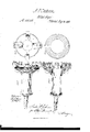
in which- Figure 1.1epresents a'side or longitudinal view of a hollow auger constructed in accordance with my invention;
Figure 2, a face view of the same;
' Figure 3, a longitudinal section ot' said auger; and
Figure 4 is a face view of a scroll used for adjusting the c utters to or from their work. 4
Similar letters ot' reference indicate corresponding parts.
My invention relates to an expanding or universal hollow auger, applicable to the cutting of round tenons and other work, and which embraces a peculiar attachment of the cutters by means of a screw-pivot and locking-screw, with slot, combined, to facilitate the setting of the cutters at their points relatively to the center of the auger. Y
A hollow auger, constructed in accordance with this invention, and which may be worked in a bit-stock or otherwise, will be found very convenient and efficient,-
Referring to the accompanying drawing- A represents the hollow spindle of' the auger, which I prefer to cast in one piece, with an annular faccplate, B, in front.
[his face-plate is slotted radially, to provide for the adjustment-or setting in and out, therein or on, ot' the cutter-slides C C, and intermediate steadying-dogs, D D, to adapt the auger to different sizes ol" work, or to .gire to it its expanding or universal character.
Said face-plate may be provided with any number of such cutter-slides or holders and steadying-dogs, all of which are operated by an entire scroll or ring, E, haring a continuous spiral thread, b, on its face, and which scroll is arranged to turn on, the spindle A, at back of the face-plate B, and so that its thread b tits within pins or ridges c c, in or onthe backs of the cutter-slides C C and dogs D D. By using au entire` scroll, the adjustment of the cutter-slides and dogs may be made continuous and in reverse directions.
F is a screw clamping-ring, made to t a screwthread, d, on thespindle in rear of the scroll E, and serving to lock the scroll, and, through it, the cutterslides and dogs', atte-r the necessary adjustment of these devices has been inade;'also, to release them when required. g
G G are the cutters, arranged on the faces of the slides C C, and being secured thereon, with facility for swiveling or adjusting them, by means ot screwpivots e e, in the centers or bodies of the cutters, and locking-screws,- ff, arranged to pass through -slots g g, outside of or beyond the screw-pivots. v
AThis mode of attaching the cutters secures the proper centering of them, or provides for the. adjustment of them after sharpening, and at other times, so that the cutting-points h h ot' two`opposite cutters will lie in one and the same line, a: x, drawn through the center of the auger, which is the propel' positionA for' the noses or cutting-points 'ot' 'the' cutters, and which, by. variation iu shape 'of the cutters, consequent on sharpening them, makes it, otherwise than `by the means described, difficult to secure.
It is preferred to make the faces of the cutter-slides' slightly concave, and the backsof theg" cutters correspondingly convex,\\'hereby, on tightening down the screw-pivots'e e, a steady outside or edge bearing is secured for the cutters.
The cutter-slides C C are formcdon their faces with clearance spaces or recesses, It' k, beneath the front or cutting-edges oi' the cutters, to provide for the'free escape ofjchips from or aboutthe cutters.
Vhat is here claimed, and desired-to be secured by Letters Patent, is-'L 4 The cutters G, secured, as described, to the cutterslides C', by means of the screw-pivots ,Hlocking-screws f, and slots g, and arranged for c,operati-10u in pairs or sets on opposite sides of the center-fof the spindle A, substantially as specified.
AUSTIN FQCUSHMAN. Witnesses: y
GEORGE G. Sim., Louis P. WALDO.
Publications (1)
| Publication Number | Publication Date |
|---|---|
| US106919A true US106919A (en) | 1870-08-30 |
Family
ID=2176395
Family Applications (1)
| Application Number | Title | Priority Date | Filing Date |
|---|---|---|---|
| US106919D Expired - Lifetime US106919A (en) | Improvement in hollow augers |
Country Status (1)
| Country | Link |
|---|---|
| US (1) | US106919A (en) |
Cited By (1)
| Publication number | Priority date | Publication date | Assignee | Title |
|---|---|---|---|---|
| USD639829S1 (en) | 2009-11-13 | 2011-06-14 | Lee Valley Tools, Ltd. | Tapered shoulder tenon cutter |
-
0
- US US106919D patent/US106919A/en not_active Expired - Lifetime
Cited By (1)
| Publication number | Priority date | Publication date | Assignee | Title |
|---|---|---|---|---|
| USD639829S1 (en) | 2009-11-13 | 2011-06-14 | Lee Valley Tools, Ltd. | Tapered shoulder tenon cutter |
Similar Documents
| Publication | Publication Date | Title |
|---|---|---|
| US136138A (en) | Improvement in hollow augers | |
| US75219A (en) | Taylor | |
| US1138423A (en) | Drill attachment. | |
| US101164A (en) | John g | |
| US512545A (en) | Tool-grinder | |
| US119096A (en) | Improvement in hollow augers | |
| US3489422A (en) | Tool adjustment assemblage for drive shafts | |
| US104958A (en) | hotchkiss | |
| US103157A (en) | Improvement in spoke-tenoning and hub-boring machines | |
| US110123A (en) | Improvement in grooving-tools | |
| US87282A (en) | Improvement in moulding-tool | |
| US243467A (en) | Chuck for holding watch-bezels | |
| US113097A (en) | Improvement in reversible knob-latches | |
| US108943A (en) | Improvement in grooving-machines | |
| US108535A (en) | Improvement in chucks | |
| US127793A (en) | Improvement in screw-cutting dies | |
| US110076A (en) | Improvement in cork-machines | |
| US108325A (en) | Improvement in lathe-dogs | |
| US552687A (en) | Adjustable cutter-head and jewel-burnisher | |
| US83349A (en) | Improved lathe-chtjck | |
| US88030A (en) | Improvement in bung-cutter | |
| US81465A (en) | Improved rotary punch | |
| US102090A (en) | Improved adjustable hollow drill | |
| US116418A (en) | Improvement in reamers | |
| US173780A (en) | Improvement in screw-cutting dies |