US10691963B2 - Method for locating a vehicle - Google Patents
Method for locating a vehicle Download PDFInfo
- Publication number
- US10691963B2 US10691963B2 US15/803,123 US201715803123A US10691963B2 US 10691963 B2 US10691963 B2 US 10691963B2 US 201715803123 A US201715803123 A US 201715803123A US 10691963 B2 US10691963 B2 US 10691963B2
- Authority
- US
- United States
- Prior art keywords
- vehicle
- data
- location
- surroundings
- objects
- Prior art date
- Legal status (The legal status is an assumption and is not a legal conclusion. Google has not performed a legal analysis and makes no representation as to the accuracy of the status listed.)
- Active, expires
Links
Images


Classifications
-
- G06K9/00825—
-
- G—PHYSICS
- G01—MEASURING; TESTING
- G01C—MEASURING DISTANCES, LEVELS OR BEARINGS; SURVEYING; NAVIGATION; GYROSCOPIC INSTRUMENTS; PHOTOGRAMMETRY OR VIDEOGRAMMETRY
- G01C21/00—Navigation; Navigational instruments not provided for in groups G01C1/00 - G01C19/00
- G01C21/26—Navigation; Navigational instruments not provided for in groups G01C1/00 - G01C19/00 specially adapted for navigation in a road network
- G01C21/28—Navigation; Navigational instruments not provided for in groups G01C1/00 - G01C19/00 specially adapted for navigation in a road network with correlation of data from several navigational instruments
- G01C21/30—Map- or contour-matching
-
- G—PHYSICS
- G06—COMPUTING OR CALCULATING; COUNTING
- G06V—IMAGE OR VIDEO RECOGNITION OR UNDERSTANDING
- G06V20/00—Scenes; Scene-specific elements
- G06V20/50—Context or environment of the image
- G06V20/56—Context or environment of the image exterior to a vehicle by using sensors mounted on the vehicle
- G06V20/58—Recognition of moving objects or obstacles, e.g. vehicles or pedestrians; Recognition of traffic objects, e.g. traffic signs, traffic lights or roads
- G06V20/584—Recognition of moving objects or obstacles, e.g. vehicles or pedestrians; Recognition of traffic objects, e.g. traffic signs, traffic lights or roads of vehicle lights or traffic lights
-
- G—PHYSICS
- G01—MEASURING; TESTING
- G01C—MEASURING DISTANCES, LEVELS OR BEARINGS; SURVEYING; NAVIGATION; GYROSCOPIC INSTRUMENTS; PHOTOGRAMMETRY OR VIDEOGRAMMETRY
- G01C21/00—Navigation; Navigational instruments not provided for in groups G01C1/00 - G01C19/00
- G01C21/38—Electronic maps specially adapted for navigation; Updating thereof
- G01C21/3804—Creation or updating of map data
- G01C21/3833—Creation or updating of map data characterised by the source of data
- G01C21/3837—Data obtained from a single source
-
- G—PHYSICS
- G01—MEASURING; TESTING
- G01C—MEASURING DISTANCES, LEVELS OR BEARINGS; SURVEYING; NAVIGATION; GYROSCOPIC INSTRUMENTS; PHOTOGRAMMETRY OR VIDEOGRAMMETRY
- G01C21/00—Navigation; Navigational instruments not provided for in groups G01C1/00 - G01C19/00
- G01C21/26—Navigation; Navigational instruments not provided for in groups G01C1/00 - G01C19/00 specially adapted for navigation in a road network
- G01C21/28—Navigation; Navigational instruments not provided for in groups G01C1/00 - G01C19/00 specially adapted for navigation in a road network with correlation of data from several navigational instruments
- G01C21/30—Map- or contour-matching
- G01C21/32—Structuring or formatting of map data
-
- G—PHYSICS
- G01—MEASURING; TESTING
- G01N—INVESTIGATING OR ANALYSING MATERIALS BY DETERMINING THEIR CHEMICAL OR PHYSICAL PROPERTIES
- G01N15/00—Investigating characteristics of particles; Investigating permeability, pore-volume or surface-area of porous materials
- G01N15/10—Investigating individual particles
- G01N15/14—Optical investigation techniques, e.g. flow cytometry
- G01N15/1429—Signal processing
- G01N15/1433—Signal processing using image recognition
-
- G01N15/1475—
-
- G—PHYSICS
- G01—MEASURING; TESTING
- G01S—RADIO DIRECTION-FINDING; RADIO NAVIGATION; DETERMINING DISTANCE OR VELOCITY BY USE OF RADIO WAVES; LOCATING OR PRESENCE-DETECTING BY USE OF THE REFLECTION OR RERADIATION OF RADIO WAVES; ANALOGOUS ARRANGEMENTS USING OTHER WAVES
- G01S19/00—Satellite radio beacon positioning systems; Determining position, velocity or attitude using signals transmitted by such systems
- G01S19/38—Determining a navigation solution using signals transmitted by a satellite radio beacon positioning system
- G01S19/39—Determining a navigation solution using signals transmitted by a satellite radio beacon positioning system the satellite radio beacon positioning system transmitting time-stamped messages, e.g. GPS [Global Positioning System], GLONASS [Global Orbiting Navigation Satellite System] or GALILEO
- G01S19/42—Determining position
- G01S19/51—Relative positioning
-
- G—PHYSICS
- G01—MEASURING; TESTING
- G01S—RADIO DIRECTION-FINDING; RADIO NAVIGATION; DETERMINING DISTANCE OR VELOCITY BY USE OF RADIO WAVES; LOCATING OR PRESENCE-DETECTING BY USE OF THE REFLECTION OR RERADIATION OF RADIO WAVES; ANALOGOUS ARRANGEMENTS USING OTHER WAVES
- G01S5/00—Position-fixing by co-ordinating two or more direction or position line determinations; Position-fixing by co-ordinating two or more distance determinations
- G01S5/02—Position-fixing by co-ordinating two or more direction or position line determinations; Position-fixing by co-ordinating two or more distance determinations using radio waves
- G01S5/0257—Hybrid positioning
- G01S5/0263—Hybrid positioning by combining or switching between positions derived from two or more separate positioning systems
-
- G—PHYSICS
- G05—CONTROLLING; REGULATING
- G05D—SYSTEMS FOR CONTROLLING OR REGULATING NON-ELECTRIC VARIABLES
- G05D1/00—Control of position, course, altitude or attitude of land, water, air or space vehicles, e.g. using automatic pilots
- G05D1/0088—Control of position, course, altitude or attitude of land, water, air or space vehicles, e.g. using automatic pilots characterized by the autonomous decision making process, e.g. artificial intelligence, predefined behaviours
-
- G—PHYSICS
- G05—CONTROLLING; REGULATING
- G05D—SYSTEMS FOR CONTROLLING OR REGULATING NON-ELECTRIC VARIABLES
- G05D1/00—Control of position, course, altitude or attitude of land, water, air or space vehicles, e.g. using automatic pilots
- G05D1/02—Control of position or course in two dimensions
- G05D1/021—Control of position or course in two dimensions specially adapted to land vehicles
- G05D1/0227—Control of position or course in two dimensions specially adapted to land vehicles using mechanical sensing means, e.g. for sensing treated area
- G05D1/0229—Control of position or course in two dimensions specially adapted to land vehicles using mechanical sensing means, e.g. for sensing treated area in combination with fixed guiding means
-
- G—PHYSICS
- G01—MEASURING; TESTING
- G01S—RADIO DIRECTION-FINDING; RADIO NAVIGATION; DETERMINING DISTANCE OR VELOCITY BY USE OF RADIO WAVES; LOCATING OR PRESENCE-DETECTING BY USE OF THE REFLECTION OR RERADIATION OF RADIO WAVES; ANALOGOUS ARRANGEMENTS USING OTHER WAVES
- G01S13/00—Systems using the reflection or reradiation of radio waves, e.g. radar systems; Analogous systems using reflection or reradiation of waves whose nature or wavelength is irrelevant or unspecified
- G01S13/86—Combinations of radar systems with non-radar systems, e.g. sonar, direction finder
-
- G—PHYSICS
- G01—MEASURING; TESTING
- G01S—RADIO DIRECTION-FINDING; RADIO NAVIGATION; DETERMINING DISTANCE OR VELOCITY BY USE OF RADIO WAVES; LOCATING OR PRESENCE-DETECTING BY USE OF THE REFLECTION OR RERADIATION OF RADIO WAVES; ANALOGOUS ARRANGEMENTS USING OTHER WAVES
- G01S13/00—Systems using the reflection or reradiation of radio waves, e.g. radar systems; Analogous systems using reflection or reradiation of waves whose nature or wavelength is irrelevant or unspecified
- G01S13/88—Radar or analogous systems specially adapted for specific applications
- G01S13/93—Radar or analogous systems specially adapted for specific applications for anti-collision purposes
- G01S13/931—Radar or analogous systems specially adapted for specific applications for anti-collision purposes of land vehicles
- G01S2013/9323—Alternative operation using light waves
-
- G—PHYSICS
- G05—CONTROLLING; REGULATING
- G05D—SYSTEMS FOR CONTROLLING OR REGULATING NON-ELECTRIC VARIABLES
- G05D1/00—Control of position, course, altitude or attitude of land, water, air or space vehicles, e.g. using automatic pilots
- G05D1/02—Control of position or course in two dimensions
- G05D1/021—Control of position or course in two dimensions specially adapted to land vehicles
- G05D1/0268—Control of position or course in two dimensions specially adapted to land vehicles using internal positioning means
- G05D1/0274—Control of position or course in two dimensions specially adapted to land vehicles using internal positioning means using mapping information stored in a memory device
-
- G05D2201/0213—
Definitions
- the present invention relates to a method for locating a vehicle.
- the present invention furthermore relates to an ascertaining device for furnishing location data for a vehicle.
- the present invention furthermore relates to a vehicle.
- ADAS advanced driver assistance systems
- UAD urban automated driving
- Localization systems that use a global localization map (e.g. retrievable from a back-end server), and a local localization map from an environmental model of the vehicle system, are often utilized in this context.
- Localization approaches for example described in C. Heigele, H. Mielenz, J. Heckel, D. Schramm, “Accurate and fast localization in unstructured environment . . . based on shape context keypoints,” in Information Fusion (FUSION), 2014 17th International Conference, Jul. 7-10, 2014, 1-7, use localization maps, and use map-matching algorithms that are optimized for the intended application, to determine a map-relative vehicle posture (position and orientation of the vehicle).
- FUSION Information Fusion
- Dynamic effects for example changing occupancy of parking spaces next to the roadway, as can occur especially in an urban environment (e.g., if the global localization map differs greatly from the local localization map), or cases in which map-relative localization is entirely impossible (e.g., in traffic jam situations), require particular map-matching approaches.
- An intelligent system for road illumination was presented by Continental AG at the IST conference in 2016.
- the system presented there possesses a variety of environmental sensors and transmits information, for example regarding defective lamps, to a central data server.
- a unit for communication with vehicle systems is also provided.
- a plurality of approaches for sensor distribution planning are also described, for example, in Y. Zou, Krishnendu Chakrabarty, “Sensor deployment and target localization based on virtual forces,” in INFOCOM 2003, Twenty-Second Annual Joint Conference of the IEEE Computer and Communications-IEEE Societies, Vol. 2, pp. 1293-1303, Vol. 2, 2003.
- Japan Patent Application No. JP 2003524775 A describes a navigation device for a vehicle in which an adaptation of sensor data to digital map data corresponding to a current position of the vehicle can be carried out.
- An object of the present invention is to provide an improved system for locating a vehicle.
- the object is achieved with a method for locating a vehicle having the steps of:
- a predictive switchover of localization modes, based on information from the local ascertaining device, is thereby advantageously supported.
- the result is that increased robustness and reliability can thereby achieved for a location system or localization system of the vehicle.
- Computation algorithms can thereby be adapted in targeted fashion to specific requirements and circumstances, the result being that computation power can be optimally utilized.
- Increased availability of a location system is thereby advantageously supported.
- the method therefore has the considerable advantage as compared with conventional systems that, inter alia, the required computation capacity and optimum switchover points in time for executing specific location algorithms are already known before the corresponding trajectory segment is traveled.
- an ascertaining device for furnishing location data for a vehicle having:
- a vehicle having:
- An advantageous refinement of the method provides that a defined reference system is used for creation of the second digital map.
- Conventional coordinate systems having known coordinates e.g. Universal Transverse Mercator [UTM] coordinates
- UDM Universal Transverse Mercator
- a further advantageous refinement of the present invention provides that substantially algorithms for sensorial detection of the second surroundings objects are used in order to locate the vehicle using the second digital map.
- the vehicle can sensorially detect objects actually present in a defined surroundings area, and can thereby effectively utilize computation capacity.
- the calculation algorithms can thereby be adapted in targeted fashion to specific circumstances.
- a further advantageous refinement of the method provides that an initialization of the algorithms for sensorial detection of the second surroundings objects is carried out upon reception of the data of the second surroundings objects by the ascertaining device.
- This advantageously supports adaptation of the system to the new circumstances already at an early stage, i.e., as a modified surroundings condition is approached, and supports availability from the outset of full computation power for a modified location mode in the new surroundings. The result is that uninterrupted driving of the vehicle is thereby supported.
- a further advantageous refinement of the method provides that the data relating to the second surroundings objects encompass at least a number of parked vehicles.
- the vehicle can thereby, for example when maneuvering in a residential area, carry out efficient location based on surroundings objects, in the form of parked vehicles, which are actually present.
- Disclosed method features may be gathered analogously from corresponding disclosed apparatus features, and vice versa. This means in particular that features, technical advantages, and embodiments relating to the method may be gathered analogously from corresponding embodiments, features, and advantages relating to the ascertaining device and/or to the vehicle, and vice versa.
- FIG. 1 schematically depicts a manner of operation of the method according to the present invention.
- FIG. 2 is a simplified depiction of a proposed vehicle.
- FIG. 3 is a simplified depiction of a proposed ascertaining device.
- FIG. 4 schematically shows the execution of an embodiment of the method according to the present invention.
- automated motor vehicle is used hereinafter with the synonymous meanings of “partly automated motor vehicle,” “autonomous motor vehicle,” and “partly autonomous motor vehicle.”
- the present invention encompasses in particular the planning and carrying out, predictively or at an early stage, a switchover of map-matching algorithms (algorithms for reconciling sensorially detected environmental data with map data from a digital map) and corresponding localization approaches.
- map-matching algorithms algorithms for reconciling sensorially detected environmental data with map data from a digital map
- the accuracy, robustness, and necessary computation capacity of the localization module can thereby be advantageously influenced.
- the example method in accordance with the present invention decides as to the map-matching and location approach to be used.
- the decision is made on the basis of a stochastic model that describes a correlation among detectable landmarks, the matching algorithm being used, and localization accuracy.
- the decision is made based on empirically acquired practical values that are represented in the example system, for example, in the form of an expert system.
- FIG. 1 shows a traffic scenario for which the example method according to the present invention is explained in principle. It shows an automated vehicle 10 moving along a trajectory 2 on a street 1 . At a first position A, vehicle 10 is located on the basis of data of a first (“global”) digital map 40 , first surroundings objects 11 (e.g. posts, traffic signs, etc.) being detected sensorially with the aid of a sensor device (not depicted) of vehicle 10 .
- first (“global”) digital map 40 first surroundings objects 11 (e.g. posts, traffic signs, etc.) being detected sensorially with the aid of a sensor device (not depicted) of vehicle 10 .
- vehicle 10 receives, from an ascertaining device 100 in the form of a local cloud system, specific data relating to second surroundings objects 12 , 13 , 14 on a road segment 3 onto which vehicle 10 then turns along trajectory 2 .
- Road segment 3 is located, for example, in a densely built-up residential area with a large number of parked vehicles 12 along road segment 3 .
- Data from surroundings objects, in the form of house walls 13 and/or hedges 14 are conveyed to vehicle 10 from ascertaining device 100 .
- at least data relating to a number of parked vehicles 12 are conveyed from ascertaining device 100 . Additional second surroundings objects that are not depicted are also conceivable.
- vehicle 10 can no longer locate itself sufficiently using the data of first surroundings objects 11 , for example because the number of first surroundings objects 11 along road segment 3 is substantially lower.
- vehicle 10 in position B can thus, at an early stage, switch over a straight-ahead location mode and now activates, for location purposes, algorithms that no longer predominantly sensorially detect first surroundings objects 11 and instead predominantly process surroundings objects 12 , 13 , 14 in the form of parked vehicles, house walls, hedges, etc.
- a second (“local”) digital map 50 is created, by way of which vehicle 10 locates itself along road segment 3 .
- the location mode for detecting and processing first surroundings objects 11 can be activated again in vehicle 10 .
- FIG. 2 is a highly simplified schematic depiction of an embodiment of a proposed vehicle 10 .
- a location device 20 with which a localization of vehicle 10 is carried out.
- Location device 20 encompasses sensor elements known per se, for example lidar, radar, camera, etc.
- Location device 20 is functionally connected to a switchover device 30 .
- location device 20 wirelessly receives, from ascertaining device 100 , data relating to second surroundings objects 12 , 13 , 14 , location device 20 recognizes that a location mode can now be changed.
- switchover device 30 switches over location algorithms within location device 20 so that localization is now carried out using correspondingly adapted algorithms of location device 20 .
- Methods known per se can be used to switch over between the algorithms. The result is to achieve, already at an early stage during the operation of vehicle 10 , a switchover of location algorithms and thus optimum utilization of computation capacity within vehicle 10 .
- An example system thus encompasses at least one ascertaining device 100 in the form of a local cloud system, receiving and transmitting units on the vehicle side, and a device for switching over algorithms for vehicle location, such that either map-matching algorithms, or algorithms for solving the SLAM problem, are executed as a consequence of the data conveyed from ascertaining device 100 .
- Each vehicle 10 receives, from the local cloud systems along trajectory 2 that is being traveled, information regarding the expected surroundings.
- FIG. 3 is a simplified block diagram of a local ascertaining device 100 , showing a sensor device 110 for detecting second surroundings objects 12 , 13 , 14 in the surroundings of ascertaining device 100 .
- the data are given basic processing and are conveyed wirelessly via a conveying device 130 , preferably to a vehicle 10 for use in a location method.
- a conveying device 130 preferably to a vehicle 10 for use in a location method.
- receivers of the data conveyed from ascertaining device 100 relating to surroundings objects 12 , 13 , 14 , for example for the purpose of evaluating traffic information.
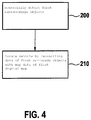
- FIG. 4 schematically shows the execution of an embodiment of the proposed method.
- first surroundings objects 11 are sensorially detected by vehicle 10 .
- vehicle 10 is located by reconciling data of sensorially detected first surroundings objects 11 with map data of a first digital map 40 ; in the event reconciliation of the data of first surroundings objects 11 with the map data of first digital map 40 to a defined extent is not possible, a second digital map 50 for a local surroundings of vehicle 10 is created and vehicle 10 is located using second digital map 50 , second digital map 50 being created using data from second surroundings objects 12 , 13 of an ascertaining device 100 , which are conveyed from ascertaining device 100 to vehicle 10 .
Landscapes
- Engineering & Computer Science (AREA)
- Radar, Positioning & Navigation (AREA)
- Remote Sensing (AREA)
- Physics & Mathematics (AREA)
- General Physics & Mathematics (AREA)
- Automation & Control Theory (AREA)
- Chemical & Material Sciences (AREA)
- Aviation & Aerospace Engineering (AREA)
- Computer Networks & Wireless Communication (AREA)
- Health & Medical Sciences (AREA)
- Pathology (AREA)
- Immunology (AREA)
- General Health & Medical Sciences (AREA)
- Analytical Chemistry (AREA)
- Biochemistry (AREA)
- Multimedia (AREA)
- Theoretical Computer Science (AREA)
- Signal Processing (AREA)
- Traffic Control Systems (AREA)
- Dispersion Chemistry (AREA)
- Life Sciences & Earth Sciences (AREA)
- Business, Economics & Management (AREA)
- Computer Vision & Pattern Recognition (AREA)
- Medical Informatics (AREA)
- Game Theory and Decision Science (AREA)
- Evolutionary Computation (AREA)
- Artificial Intelligence (AREA)
- Navigation (AREA)
Abstract
Description
-
- sensorial detection of first surroundings objects by the vehicle;
- locating the vehicle by reconciling data of the sensorially detected first surroundings objects with map data of a first digital map,
- in the case in which reconciliation of the data of the first surroundings objects with the map data of the first digital map to a defined extent is not possible, a second digital map for a local surroundings of the vehicle being created and location of the vehicle being carried out using the second digital map,
- data from second surroundings objects of an ascertaining device, which are conveyed from the ascertaining device to the vehicle, being used for creation of the second digital map.
-
- a sensor device for detecting defined surroundings objects;
- an evaluation device for evaluating data of the detected surroundings objects; and
- a conveying device for wirelessly conveying the evaluated data relating to the surroundings objects.
-
- a location device; and
- a switchover device for switching over an operating mode of the location device as a function of data that are received during operation of the vehicle and relate to defined surroundings objects from an ascertaining device.
Claims (8)
Applications Claiming Priority (3)
| Application Number | Priority Date | Filing Date | Title |
|---|---|---|---|
| DE102016221688.0A DE102016221688A1 (en) | 2016-11-04 | 2016-11-04 | Method of locating a vehicle |
| DE102016221688.0 | 2016-11-04 | ||
| DE102016221688 | 2016-11-04 |
Publications (2)
| Publication Number | Publication Date |
|---|---|
| US20180129890A1 US20180129890A1 (en) | 2018-05-10 |
| US10691963B2 true US10691963B2 (en) | 2020-06-23 |
Family
ID=62002920
Family Applications (1)
| Application Number | Title | Priority Date | Filing Date |
|---|---|---|---|
| US15/803,123 Active 2038-05-11 US10691963B2 (en) | 2016-11-04 | 2017-11-03 | Method for locating a vehicle |
Country Status (3)
| Country | Link |
|---|---|
| US (1) | US10691963B2 (en) |
| CN (1) | CN108020229B (en) |
| DE (1) | DE102016221688A1 (en) |
Families Citing this family (11)
| Publication number | Priority date | Publication date | Assignee | Title |
|---|---|---|---|---|
| EP3376249A1 (en) * | 2017-03-17 | 2018-09-19 | Veoneer Sweden AB | Enhanced object position detection |
| JP6843712B2 (en) * | 2017-07-27 | 2021-03-17 | フォルシアクラリオン・エレクトロニクス株式会社 | In-vehicle processing device |
| DE102017222810A1 (en) | 2017-12-14 | 2019-06-19 | Robert Bosch Gmbh | Method for creating a feature-based localization map for a vehicle taking into account characteristic structures of objects |
| DE102018219602A1 (en) * | 2018-11-15 | 2020-05-20 | Robert Bosch Gmbh | Method of detecting card errors |
| DE102018221178A1 (en) * | 2018-12-06 | 2020-06-10 | Robert Bosch Gmbh | Localization system |
| DE102019207215A1 (en) * | 2019-05-17 | 2020-11-19 | Robert Bosch Gmbh | Method for using a feature-based localization map for a vehicle |
| DE102019207212A1 (en) * | 2019-05-17 | 2020-11-19 | Robert Bosch Gmbh | Method and device for processing sensor data |
| CN112200765B (en) * | 2020-09-04 | 2024-05-14 | 浙江大华技术股份有限公司 | Method and device for determining false-detected key points in vehicle |
| DE102021212244A1 (en) | 2021-10-29 | 2023-05-04 | Robert Bosch Gesellschaft mit beschränkter Haftung | Process for the secure transmission of data in a highly automated vehicle using encrypted QR codes |
| CN117734723B (en) * | 2022-09-14 | 2024-10-29 | 北京三快在线科技有限公司 | Autopilot system, autopilot vehicle and cloud device |
| DE102023109572A1 (en) | 2023-04-17 | 2024-10-17 | Valeo Schalter Und Sensoren Gmbh | Method for detecting a position of an at least partially automated motor vehicle by a position detection device, computer program product, computer-readable storage medium, position detection device and assistance system |
Citations (4)
| Publication number | Priority date | Publication date | Assignee | Title |
|---|---|---|---|---|
| JP2003524775A (en) | 1999-11-04 | 2003-08-19 | メルテック・マルチ−エピトープ−リガンド−テクノロジーズ・ゲーエムベーハー | Automatic analysis of microscope images |
| WO2015156821A1 (en) | 2014-04-11 | 2015-10-15 | Nissan North America, Inc. | Vehicle localization system |
| US20170307746A1 (en) * | 2016-04-22 | 2017-10-26 | Mohsen Rohani | Systems and methods for radar-based localization |
| US20180031375A1 (en) * | 2016-08-01 | 2018-02-01 | Autochips Inc. | Methods, apparatuses, and mobile terminals for positioning and searching for a vehicle |
Family Cites Families (4)
| Publication number | Priority date | Publication date | Assignee | Title |
|---|---|---|---|---|
| JP3821018B2 (en) | 2002-03-05 | 2006-09-13 | 株式会社デンソー | Navigation device |
| CN104943684B (en) * | 2014-03-31 | 2017-09-29 | 比亚迪股份有限公司 | Pilotless automobile control system and the automobile with it |
| CN104062973B (en) * | 2014-06-23 | 2016-08-24 | 西北工业大学 | A kind of mobile robot based on logos thing identification SLAM method |
| CN105953798B (en) * | 2016-04-19 | 2018-09-18 | 深圳市神州云海智能科技有限公司 | The pose of mobile robot determines method and apparatus |
-
2016
- 2016-11-04 DE DE102016221688.0A patent/DE102016221688A1/en active Pending
-
2017
- 2017-11-03 US US15/803,123 patent/US10691963B2/en active Active
- 2017-11-06 CN CN201711077592.7A patent/CN108020229B/en active Active
Patent Citations (5)
| Publication number | Priority date | Publication date | Assignee | Title |
|---|---|---|---|---|
| JP2003524775A (en) | 1999-11-04 | 2003-08-19 | メルテック・マルチ−エピトープ−リガンド−テクノロジーズ・ゲーエムベーハー | Automatic analysis of microscope images |
| WO2015156821A1 (en) | 2014-04-11 | 2015-10-15 | Nissan North America, Inc. | Vehicle localization system |
| US20170030722A1 (en) * | 2014-04-11 | 2017-02-02 | Nissan North America, Inc. | Vehicle localization system |
| US20170307746A1 (en) * | 2016-04-22 | 2017-10-26 | Mohsen Rohani | Systems and methods for radar-based localization |
| US20180031375A1 (en) * | 2016-08-01 | 2018-02-01 | Autochips Inc. | Methods, apparatuses, and mobile terminals for positioning and searching for a vehicle |
Non-Patent Citations (5)
| Title |
|---|
| Heigele et al., "Accurate and fast localization in unstructured environment . . . based on shape context keypoints," in Information Fusion (FUSION), 2014 17th International Conference, Jul. 7-10, 2014, 1-7. |
| Meyer-Delius et al., "Temporary maps for robust localization in semi-static environments," in Intelligent Robots and Systems (IROS), 2010 IEEE/RSJ International Conference, Oct. 18-22, 2010, pp. 5750-5722. |
| Rohde et al., "Model-Based Derivation of Perception Accuracy Requirements for Vehicle Localization in Urban Environments," in Intelligent Transportation Systems (ITSC), 2015 IEEE 18th International Conference, Sep. 18, 2015, pp. 712-718. |
| Zou et al., "Sensor deployment and target localization based on virtual forces," in INFOCOM 2003, Twenty-Second Annual Joint Conference of the IEEE Computer and Communications-IEEE Societies, vol. 2, pp. 1293-1303, vol. 2, 2003. |
| Zou et al., "Sensor deployment and target localization based on virtual forces," in INFOCOM 2003, Twenty-Second Annual Joint Conference of the IEEE Computer and Communications—IEEE Societies, vol. 2, pp. 1293-1303, vol. 2, 2003. |
Also Published As
| Publication number | Publication date |
|---|---|
| CN108020229A (en) | 2018-05-11 |
| US20180129890A1 (en) | 2018-05-10 |
| DE102016221688A1 (en) | 2018-05-09 |
| CN108020229B (en) | 2023-11-10 |
Similar Documents
| Publication | Publication Date | Title |
|---|---|---|
| US10691963B2 (en) | Method for locating a vehicle | |
| US10677597B2 (en) | Method and system for creating a digital map | |
| CN110546696B (en) | Method for automatically generating and updating data sets for autonomous vehicles | |
| US8301374B2 (en) | Position estimation for ground vehicle navigation based on landmark identification/yaw rate and perception of landmarks | |
| US11351986B2 (en) | In-vehicle processing apparatus | |
| US10829154B2 (en) | Method and device for operating a vehicle | |
| US10621861B2 (en) | Method and system for creating a lane-accurate occupancy grid map for lanes | |
| US9409644B2 (en) | Automotive drone deployment system | |
| CN103781685B (en) | The autonomous drive-control system of vehicle | |
| US10151598B2 (en) | Method and device for operating a vehicle and driver assistance system | |
| CN105814404B (en) | Method and system for locating mobile devices | |
| US10369993B2 (en) | Method and device for monitoring a setpoint trajectory to be traveled by a vehicle for being collision free | |
| US11163308B2 (en) | Method for creating a digital map for an automated vehicle | |
| AU2010290950B2 (en) | Path determination | |
| US20260009649A1 (en) | Mobile body, method of controlling mobile body, and program | |
| US20180347991A1 (en) | Method, device, map management apparatus, and system for precision-locating a motor vehicle in an environment | |
| JP7750246B2 (en) | Information processing device, information processing system, method, and program | |
| JP2020506387A (en) | Method for locating a more highly automated, eg, highly automated vehicle (HAF) with a digital location map | |
| KR20110094954A (en) | Vehicle autonomous driving system based on driving history information | |
| WO2022130720A1 (en) | Dividing line recognition device | |
| JP7151905B2 (en) | Vehicle position specifying device and vehicle position specifying method | |
| JP2025072732A (en) | Autonomous Driving System | |
| US20190285419A1 (en) | Method and device for determining an exact position of a vehicle with the aid of radar signatures of the vehicle surroundings | |
| KR101397933B1 (en) | Device for creating traveling information of unmanned ground vehicle, unmanned ground vehicle having the same and control method thereof | |
| US12553724B2 (en) | Method and device for creating a first map |
Legal Events
| Date | Code | Title | Description |
|---|---|---|---|
| FEPP | Fee payment procedure |
Free format text: ENTITY STATUS SET TO UNDISCOUNTED (ORIGINAL EVENT CODE: BIG.); ENTITY STATUS OF PATENT OWNER: LARGE ENTITY |
|
| AS | Assignment |
Owner name: ROBERT BOSCH GMBH, GERMANY Free format text: ASSIGNMENT OF ASSIGNORS INTEREST;ASSIGNORS:MIELENZ, HOLGER;ROHDE, JAN;SIGNING DATES FROM 20171206 TO 20171211;REEL/FRAME:044564/0845 |
|
| STPP | Information on status: patent application and granting procedure in general |
Free format text: DOCKETED NEW CASE - READY FOR EXAMINATION |
|
| STPP | Information on status: patent application and granting procedure in general |
Free format text: NON FINAL ACTION MAILED |
|
| STPP | Information on status: patent application and granting procedure in general |
Free format text: RESPONSE TO NON-FINAL OFFICE ACTION ENTERED AND FORWARDED TO EXAMINER |
|
| STPP | Information on status: patent application and granting procedure in general |
Free format text: FINAL REJECTION MAILED |
|
| STPP | Information on status: patent application and granting procedure in general |
Free format text: ADVISORY ACTION MAILED |
|
| STPP | Information on status: patent application and granting procedure in general |
Free format text: DOCKETED NEW CASE - READY FOR EXAMINATION |
|
| STPP | Information on status: patent application and granting procedure in general |
Free format text: PUBLICATIONS -- ISSUE FEE PAYMENT VERIFIED |
|
| STCF | Information on status: patent grant |
Free format text: PATENTED CASE |
|
| MAFP | Maintenance fee payment |
Free format text: PAYMENT OF MAINTENANCE FEE, 4TH YEAR, LARGE ENTITY (ORIGINAL EVENT CODE: M1551); ENTITY STATUS OF PATENT OWNER: LARGE ENTITY Year of fee payment: 4 |