US10691905B2 - Field-upgradable barcode readers - Google Patents
Field-upgradable barcode readers Download PDFInfo
- Publication number
- US10691905B2 US10691905B2 US16/167,159 US201816167159A US10691905B2 US 10691905 B2 US10691905 B2 US 10691905B2 US 201816167159 A US201816167159 A US 201816167159A US 10691905 B2 US10691905 B2 US 10691905B2
- Authority
- US
- United States
- Prior art keywords
- field
- window
- barcode reader
- insert
- fold mirror
- Prior art date
- Legal status (The legal status is an assumption and is not a legal conclusion. Google has not performed a legal analysis and makes no representation as to the accuracy of the status listed.)
- Active
Links
- 238000003384 imaging method Methods 0.000 claims abstract description 42
- 230000003287 optical effect Effects 0.000 claims description 33
- 230000000712 assembly Effects 0.000 claims description 17
- 238000000429 assembly Methods 0.000 claims description 17
- 238000000034 method Methods 0.000 description 15
- 230000008901 benefit Effects 0.000 description 6
- 230000008569 process Effects 0.000 description 6
- 230000006870 function Effects 0.000 description 4
- 238000003860 storage Methods 0.000 description 4
- 230000009471 action Effects 0.000 description 3
- 230000008859 change Effects 0.000 description 3
- 238000004519 manufacturing process Methods 0.000 description 3
- 238000013461 design Methods 0.000 description 2
- 230000006872 improvement Effects 0.000 description 2
- 238000012986 modification Methods 0.000 description 2
- 230000004048 modification Effects 0.000 description 2
- 230000000717 retained effect Effects 0.000 description 2
- 241000251468 Actinopterygii Species 0.000 description 1
- 238000013459 approach Methods 0.000 description 1
- 238000003491 array Methods 0.000 description 1
- 230000000694 effects Effects 0.000 description 1
- 238000005516 engineering process Methods 0.000 description 1
- 238000005286 illumination Methods 0.000 description 1
- 230000003993 interaction Effects 0.000 description 1
- 238000012544 monitoring process Methods 0.000 description 1
- 238000012545 processing Methods 0.000 description 1
- 238000005303 weighing Methods 0.000 description 1
Images


Classifications
-
- G—PHYSICS
- G06—COMPUTING; CALCULATING OR COUNTING
- G06K—GRAPHICAL DATA READING; PRESENTATION OF DATA; RECORD CARRIERS; HANDLING RECORD CARRIERS
- G06K7/00—Methods or arrangements for sensing record carriers, e.g. for reading patterns
- G06K7/10—Methods or arrangements for sensing record carriers, e.g. for reading patterns by electromagnetic radiation, e.g. optical sensing; by corpuscular radiation
- G06K7/10544—Methods or arrangements for sensing record carriers, e.g. for reading patterns by electromagnetic radiation, e.g. optical sensing; by corpuscular radiation by scanning of the records by radiation in the optical part of the electromagnetic spectrum
- G06K7/10712—Fixed beam scanning
- G06K7/10722—Photodetector array or CCD scanning
-
- G—PHYSICS
- G06—COMPUTING; CALCULATING OR COUNTING
- G06K—GRAPHICAL DATA READING; PRESENTATION OF DATA; RECORD CARRIERS; HANDLING RECORD CARRIERS
- G06K7/00—Methods or arrangements for sensing record carriers, e.g. for reading patterns
- G06K7/10—Methods or arrangements for sensing record carriers, e.g. for reading patterns by electromagnetic radiation, e.g. optical sensing; by corpuscular radiation
- G06K7/10544—Methods or arrangements for sensing record carriers, e.g. for reading patterns by electromagnetic radiation, e.g. optical sensing; by corpuscular radiation by scanning of the records by radiation in the optical part of the electromagnetic spectrum
- G06K7/10821—Methods or arrangements for sensing record carriers, e.g. for reading patterns by electromagnetic radiation, e.g. optical sensing; by corpuscular radiation by scanning of the records by radiation in the optical part of the electromagnetic spectrum further details of bar or optical code scanning devices
- G06K7/10831—Arrangement of optical elements, e.g. lenses, mirrors, prisms
-
- G—PHYSICS
- G06—COMPUTING; CALCULATING OR COUNTING
- G06K—GRAPHICAL DATA READING; PRESENTATION OF DATA; RECORD CARRIERS; HANDLING RECORD CARRIERS
- G06K7/00—Methods or arrangements for sensing record carriers, e.g. for reading patterns
- G06K7/10—Methods or arrangements for sensing record carriers, e.g. for reading patterns by electromagnetic radiation, e.g. optical sensing; by corpuscular radiation
- G06K7/14—Methods or arrangements for sensing record carriers, e.g. for reading patterns by electromagnetic radiation, e.g. optical sensing; by corpuscular radiation using light without selection of wavelength, e.g. sensing reflected white light
- G06K7/1404—Methods for optical code recognition
- G06K7/1408—Methods for optical code recognition the method being specifically adapted for the type of code
- G06K7/1413—1D bar codes
Definitions
- the present patent relates generally to barcode readers and, in particular, relates to field-upgradable barcode readers.
- Bi-optic barcode readers are typically formed with a horizontal window and a vertical window arranged in a way that image data can be captured by internal imaging components (e.g., imaging sensors) through either of the two windows. While these bi-optic barcode readers are effective at reading barcodes, known barcode readers are unable to provide non-barcode imaging data that may be used to further monitor the checkout process.
- FIG. 1 illustrates a perspective view of an example checkout workstation in accordance with the teachings of this disclosure.
- FIG. 2 illustrates a perspective view of an example barcode reader that can be used to implement the barcode reader of the checkout workstation of FIG. 1 .
- FIG. 3 illustrates a partial interior perspective view of the barcode reader of FIG. 2 .
- FIG. 4 illustrates example first and second sub fields of view projecting from a generally vertical window of the barcode reader of FIG. 2 .
- FIG. 5 illustrates example third and fourth sub fields of view projecting from a generally horizontal window of the barcode reader of FIG. 2 .
- FIG. 6 illustrates a perspective view of an example insert that is structured to be received within an example receptacle of the barcode reader of FIG. 2 and is structured to carry a camera in a landscape orientation.
- FIG. 7 illustrates a perspective view of another example insert that is structured to be received within the receptacle of the barcode reader of FIG. 2 and is structured to carry a camera in a portrait orientation.
- FIG. 8 illustrates a perspective view of another example insert that is structured to be received within the receptacle of the barcode reader of FIG. 2 and is structured to cover the receptacle when the barcode reader is not implemented with an additional camera.
- FIG. 9 illustrates an expanded rear perspective view of the barcode reader of FIG. 2 including the insert of FIG. 6 that shows an example rear cover of the barcode reader detached from a housing portion of the barcode reader.
- FIG. 10 illustrates a perspective view of the rear cover of the barcode reader of FIG. 9 .
- FIG. 11 illustrates an example vertical field of view of the barcode reader of FIG. 2 when the barcode reader is implemented with the insert of FIG. 6 .
- FIG. 12 illustrates an example horizontal field of view of the barcode reader of FIG. 2 when the barcode reader is implemented with the insert of FIG. 6 .
- FIG. 13 illustrates an expanded rear perspective view of the barcode reader of FIG. 2 including the insert of FIG. 7 that shows the rear cover of the barcode reader detached from the housing portion of the barcode reader.
- FIG. 14 illustrates an example vertical field of view of the barcode reader of FIG. 2 when the barcode reader is implemented with the insert of FIG. 7 .
- FIG. 15 illustrates an example horizontal field of view of the barcode reader of FIG. 2 when the barcode reader is implemented with the insert of FIG. 7 .
- the examples disclosed herein relate to scanners that can be field implemented with example cameras that are structured to obtain non-barcode data.
- the cameras may be implemented as color cameras.
- the scanners sometimes referred to as barcode readers, have a generally horizontal platter including a horizontal window and a tower including a vertical window.
- Barcode image data can be obtained by barcode cameras through the horizontal window and the vertical window and non-barcode data can be obtained by at least one non-barcode camera through the vertical window.
- the non-barcode data may be used for different purposes such as, for example, building a product database and/or monitoring the checkout process at a retail store for fraudulent activity.
- the scanner includes an example receptacle that is structured to receive different example inserts.
- the inserts are structured to carry a camera in a desired orientation and/or to carry a camera to provide a desired field of view.
- the image data captured by the additional camera can have a field of view (FOV) of between about 30° and 135°.
- FOV field of view
- a “fish eye” lens can be used with the camera.
- the inserts may be referred to as adapters or field-installable imaging assembly inserts.
- a first insert can be used.
- a second insert can be used.
- the first orientation may be a landscape or wide orientation and the second orientation may be a portrait or tall orientation.
- the receptacle of the scanner is structured to fit a number of different inserts, each being associated with a different customer preference and/or requirement.
- the cameras may be angled at +/ ⁇ 45° relative to a horizontal plane. While the above example mentions the insert carrying one of the non-barcode cameras, the insert can alternatively be implemented as a plug or a cover that can be replaced if the customer chooses to change the configuration of the scanner to include an additional camera.
- a field-upgradeable barcode reader is configured to be supported by a workstation.
- the field-upgradeable barcode reader includes a first housing portion supporting a generally horizontal platter having a generally horizontal window.
- the field-upgradable bar code reader also includes a second housing portion supporting a generally vertical window.
- the second housing portion has a first cover removably attached thereto.
- the field-upgradeable barcode reader also includes an image capture arrangement having a first set of optical components and a second set of optical components.
- the first set of optical components is positioned at least partially within the first housing portion.
- the first set of optical components is configured to produce and direct a first field of view (FOV) through the generally horizontal window.
- the second set of optical components includes a first fold mirror and a second fold mirror. Each of the first fold mirror and the second fold mirror is positioned at least partially within the second housing portion.
- the second set of optical components is configured to produce and direct a second FOV and a third FOV through the generally vertical window such that the first fold mirror redirects the second FOV through the generally vertical window and the second fold mirror redirects the third FOV through the generally vertical window.
- the second housing includes a receptacle configured to alternatively receive one of a second cover and a field-installable imaging assembly insert.
- the field-installable imaging assembly insert is configured to receive an image acquisition assembly.
- the receptacle is positioned between the first fold mirror and the second fold mirror.
- a field-upgradeable barcode reader is configured to be supported by a workstation.
- the field-upgradeable barcode reader includes a first housing portion supporting a generally horizontal platter having a generally horizontal window.
- the field-upgradable barcode reader also includes a second housing portion supporting a generally vertical window.
- the second housing includes a receptacle configured to alternatively receive one of a cover and a field-installable imaging assembly insert.
- the field-installable imaging assembly insert is configured to receive an image acquisition assembly.
- the field-upgradeable barcode reader includes an image capture arrangement having a first set of optical components and a second set of optical components.
- the first set of optical components is positioned at least partially within the first housing portion.
- the first set of optical components is configured to produce and direct a first field of view (FOV) through the generally horizontal window.
- the second set of optical components includes a first fold mirror and a second fold mirror.
- the first fold mirror and the second fold mirror are positioned at least partially within the second housing portion.
- the second set of optical components is configured to produce and direct a second FOV and a third FOV through the generally vertical window such that the first fold mirror redirects the second FOV through the generally vertical window and the second fold mirror redirects the third FOV through the generally vertical window.
- a barcode reader in a third example, includes a housing carrying first and second imager assemblies.
- the first and second imager assemblies are to obtain barcode data.
- the housing defines a receptacle to removably receive any one of: 1) a cover; 2) a first insert to carry a first camera; or 3) a second insert to carry the first camera or a second camera.
- the first insert is to enable the first camera to be positioned in a first orientation.
- the second insert is to enable the first camera or the second camera to be positioned in a second orientation.
- the barcode reader includes a first window and a second window.
- the first imager assembly is to capture first barcode data of the barcode data through the first window and the second imager assembly is to capture second barcode data of the barcode data through the second window.
- the first imager assembly includes a first image sensor and first optical components to provide the first image sensor with a first field of view through the first window and the second imager assembly includes a second image sensor and second optical components to provide the second image sensor with a second field of view and a third field of view through the second window.
- a barcode reader in a fourth example, includes a housing carrying first and second imager assemblies to obtain barcode data.
- the barcode reader also includes a camera to be disposed in the housing. The camera is different from the first and second imager assemblies.
- the barcode reader also includes an assembly configured to enable an orientation of the camera to change between a first orientation and a second orientation.
- the assembly includes a receptacle of the housing that is configured to alternatively receive one of a first field-installable insert or a second field-installable insert.
- the first field-installable insert is to carry the camera when the first field-installable insert is received by the receptacle and the second field-installable insert is to carry the camera when the second field-installable insert is received by the receptacle.
- FIG. 1 illustrates a perspective view of a point-of-sale (POS) system 100 having a workstation 102 with a counter 104 , a bi-optical (also referred to as “bi-optic”) barcode reader 106 and an additional camera 107 at least partially positioned within the workstation 102 .
- the camera 107 may be referred to as an image acquisition assembly and may be implemented as a color camera or a camera that is configured to obtain non-barcode data.
- the POS system 100 is often managed by a store employee such as a clerk 108 . However, in other cases the POS system 100 may be a part of a so-called self-checkout lane where instead of a clerk, a customer is responsible for checking out his or her own products.
- the barcode reader 106 includes a lower housing 112 and a raised housing 114 .
- the lower housing 112 may be referred to as a first housing portion and the raised housing 114 may be referred to as a tower or a second housing portion.
- the lower housing 112 includes a top portion 116 with a first optically transmissive window 118 positioned therein along a generally horizontal plane relative to the overall configuration and placement of the barcode reader 106 .
- the top portion 116 may include a removable or a non-removable platter (e.g., a weighing platter).
- the top portion 116 can also be viewed as being positioned substantially parallel with the counter 104 surface.
- the phrase “substantially parallel” means+/ ⁇ 10° of parallel and/or accounts for manufacturing tolerances. It's worth noting that while, in FIG. 1 , the counter 104 and the top portion 116 are illustrated as being about co-planar, that does not have to be the case for the platter and the counter 104 to be considered substantially parallel. In some instances, the counter 104 may be raised or lowered relative to the top surface of the top portion 116 , where the top portion 116 is still viewed as being positioned substantially parallel with the counter 104 surface.
- the raised housing 114 is configured to extend above the top portion 116 and includes a second optically transmissive window 120 positioned in a generally upright plane relative to the top portion 116 and/or the first optically transmissive window 118 .
- references to “upright” include, but are not limited to, vertical. Thus, as an example, something that is upright may deviate from a vertical axis/plane by as much as 45 degrees.
- a product 122 such as for example a bottle, is swiped past the barcode reader 106 such that a barcode 124 associated with the product 122 is digitally read through at least one of the first and second optically transmissive windows 118 , 120 .
- This is particularly done by positioning the product 122 within the fields of view (FsOV) of the digital imaging sensor(s) housed inside the barcode reader 106 .
- the camera 107 obtains image data of the product 122 .
- the image data obtained by the camera 107 may have different uses. For example, the image data can be processed to verify that the product 122 scanned matches the barcode 124 and/or image data can be used to populate a database.
- FIG. 2 illustrates a cross-sectional perspective view of an example barcode reader 200 that can be used to implement the barcode reader 106 of FIG. 1 .
- the barcode reader 200 includes an example first housing portion 202 that supports a generally horizontal platter 204 having a first window 206 .
- the first window 206 may be implemented as an optically transmissive window and may be referred to as a generally horizontal window.
- the barcode reader 200 is also shown including an example second housing portion 208 that supports a second window 210 .
- the second housing portion 208 may be referred to as a tower and the second window 210 may be referred to as a generally vertical window.
- the second window 210 may be implemented as an optically transmissive window.
- the first window 206 is substantially perpendicular relative to the second window 210 .
- the phrase “substantially perpendicular” means+/ ⁇ 10° of perpendicular and/or accounts for manufacturing tolerances.
- the barcode reader 200 includes a printed circuit board (PCB) 211 with a first imaging assembly 212 and a second imaging assembly 214 .
- the imaging assemblies 212 , 214 may be referred to as cameras or imager assemblies.
- Each of the imaging assemblies 212 , 214 includes an imaging sensor having a plurality of photosensitive elements that define a substantially flat surface along with other components such as a housing and lens(es) for capturing image data for a FOV.
- the arrangement and configuration of the components including the imaging sensor, the photosensitive elements, the housing, the lens(es) define a specific FOV for each of the imaging assemblies 212 , 214 .
- the first imaging assembly 212 and its imaging sensor are configured to capture image data over a first field of view (FOV) 216 and the second imaging assembly 214 and its imaging sensor are configured to capture image data over a second field of view (FOV) 218 .
- the image data captured by the first and second imaging assemblies 212 , 214 may include barcode data.
- the barcode reader 200 includes a first fold mirror 222 positioned to redirect the first FOV 216 toward a first splitter mirror 224 .
- the first splitter mirror 224 is structured and positioned to split the first FOV 216 into a first sub FOV 402 ( FIG. 4 ) and a second sub FOV 404 ( FIG. 4 ).
- the first sub FOV 402 is directed toward a second fold mirror 226 and the second sub FOV 404 is directed toward a third fold mirror 302 ( FIG. 3 ).
- the second fold mirror 226 redirects the first sub FOV 402 out of the second window 210 as shown in FIG.
- the first imaging assembly 212 is configured to produce the first FOV 216 and the mirrors 222 , 224 , 226 , 302 are at least partially positioned in the second housing portion 208 to direct the first and second sub FsOV 402 , 404 through the second window 210 as shown in FIG. 4 .
- the mirrors 222 , 224 , 226 , 302 and the first imaging assembly 212 are configured to capture barcode data through the second window 210 .
- the mirrors 226 , 302 and/or the first imaging assembly 212 may be referred to as optical components.
- the barcode reader 200 includes a second splitter mirror 228 .
- the second splitter mirror 228 is structured and positioned to split the second FOV 218 into a third sub field of view 230 and a fourth sub FOV 502 ( FIG. 5 ).
- the third sub FOV 230 is directed toward a third fold mirror 232 which directs the third sub FOV 230 to a fourth fold mirror 304 ( FIG. 3 ).
- the fourth fold mirror 304 is structured and positioned to redirect the third sub FOV 230 out of the first window 206 as shown in FIG. 5 .
- the fourth sub FOV 502 is directed toward a fifth fold mirror 306 ( FIG.
- the second imaging assembly 214 is configured to produce the second FOV 218 and the mirrors 232 , 304 , 306 , 308 are at least partially positioned in the first housing portion 202 to direct the third and fourth sub FsOV 230 , 502 through the first window 206 .
- the mirrors 228 , 232 , 304 , 306 , 308 and the second imaging assembly 214 are configured to capture barcode data through the first window 206 .
- the mirrors 232 , 304 , 306 , 308 and/or the second imaging assembly 214 may be referred to as optical components.
- the mirrors 222 , 224 , 226 , 232 , 302 , 232 , 304 , 306 , 308 and the first and second imaging assemblies 212 , 214 may be referred to as an image capture arrangement. While the mirrors 222 , 224 , 226 , 232 , 302 , 304 , 306 , 308 are shown in a particular arrangement, the precise angle and position of the mirrors 222 , 224 , 226 , 232 , 302 , 304 , 306 , 308 can be varied to achieve a desired FOV path direction.
- a divider 207 of the second housing portion 208 defines an example receptacle 234 .
- the receptacle is shown positioned between the fold mirrors 226 , 302 and may be referred to as an aperture or an opening.
- the divider 207 defines a cavity 209 in which the mirrors 222 , 223 , 224 , 302 and/or the first imaging assembly 212 are at least partially positioned.
- the receptacle 234 is structured to accept different inserts such as, for example, a first insert 602 shown in FIG. 6 , a second insert 702 shown in FIG. 7 and a third insert 802 shown in FIG. 8 .
- the first insert 602 is structured to carry the camera 107 in a landscape or first orientation
- the second insert 702 is structured to carry the camera 107 in a portrait or second orientation
- the third insert 802 is structured to cover the receptacle 234 when the barcode reader 200 is not implemented with the camera 107 or, more generally, prior to the barcode reader 200 being field upgraded with the camera 107 .
- the barcode reader 200 is structured to carry the camera 107 when the inserts 602 , 702 are received by the receptacle 234 to enable additional image data to be obtained and accessed by the PCB 211 .
- the barcode reader 200 may include an additional PCB to which the camera 107 is coupled when the barcode reader 200 is implemented with the camera 107 .
- the additional image data may include non-barcode data or color image data.
- the PCB 211 includes an example decode assembly 236 .
- the data acquired by the imaging assemblies 212 , 214 is transmitted or otherwise accessed by the decode assembly 236 , where the data is processed and/or analyzed in an effort to detect and decode a valid barcode(s), for example.
- components such as a controller for controlling the imaging assemblies 212 , 214 , the camera 107 and/or the decode assembly 236 can be installed on the PCB 211 .
- components like a controller for controlling the imaging assemblies, the illumination assemblies and/or the decode assembly can also be installed on the PCB 211 to detect non-barcode data from the camera 107 including the identification of the product 122 being scanned, for example.
- a controller may be positioned separate from the PCB. Signal data may be sent to/from the PCB 211 via interface connectors 238 .
- FIG. 3 illustrates a partial interior perspective view of the barcode reader 200 of FIG. 2 .
- the first splitter mirror 224 is arranged to split the first FOV 216 into the first sub FOV 402 directed toward the second fold mirror 226 and the second sub FOV 404 directed toward the third fold mirror 302 .
- the second and third fold mirrors 226 , 302 are illustrated being positioned to direct the first and second sub FsOV 402 , 404 out of the second window 210 .
- the second splitter mirror 228 is arranged to split the second FOV 218 into the third sub FOV 230 directed toward the third fold mirror 232 and the fourth sub FOV 502 directed toward the fifth fold mirror 306 .
- the third fold mirror 232 is shown positioned to direct the third sub FOV 230 to the fourth fold mirror 304 which directs the third sub FOV 230 out of the first window 206 and the fifth fold mirror 306 is shown positioned to direct the fourth sub FOV 502 to the sixth fold mirror 308 which directs the fourth sub FOV 502 out of the first window 206 .
- FIG. 4 illustrates the first and second sub FsOV 402 , 404 projecting from the second window 210 of the barcode reader 200 of FIG. 2 .
- the fold mirrors 226 , 302 are positioned such that the first sub-FOV 402 and the second sub-FOV 404 intersect above the first window 206 and in a product-scanning region 406 of the barcode reader 200 .
- the product-scanning region 406 is the general area where the product 122 is expected to be presented for image capture by the barcode reader 200 .
- the fold mirrors 226 , 302 can be arranged to cause the first sub-FOV 402 and the second sub-FOV 404 to intersect partially.
- the fold mirrors 226 , 302 can be arranged to cause the first sub-FOV 402 and the second sub-FOV 404 to intersect fully. In still other instances, the fold mirrors 226 , 302 can be arranged to cause a centroidal axis of each of the first sub-FOV 402 and the second sub-FOV 404 to intersect with or without regard for the cross-sectional dimensions of the FsOV.
- FIG. 5 illustrates the third and fourth sub FsOV 230 , 502 projecting from the first window 206 of the barcode reader 200 of FIG. 2 .
- the fold mirrors 232 , 304 , 306 , 308 are positioned such that the third sub FOV 230 and the fourth sub FOV 502 intersect in front of the second window 210 and in the product-scanning region 406 of the barcode reader 200 .
- the fold mirrors 232 , 304 , 306 , 308 can be arranged to cause the third sub FOV 230 and the fourth sub FOV 502 to intersect partially.
- the fold mirrors 232 , 304 , 306 , 308 can be arranged to cause the first sub-FOV 402 and the second sub-FOV 404 to intersect fully.
- the fold mirrors 226 , 302 can be arranged to cause a centroidal axis of each of the first sub-FOV 402 and the second sub-FOV 404 to intersect with or without regard for the cross-sectional dimensions of the FsOV.
- FIG. 6 illustrates a perspective view of the example insert 602 that is structured to be received within the receptacle 234 of the barcode reader 200 .
- the insert 602 includes a bottom wall 604 from which side walls 606 , 608 and a front wall 610 extend.
- lips 612 , 614 , 616 , 618 , 620 , 622 extend from edges 624 , 626 , 628 , 630 , 632 , 634 of the walls 604 , 606 , 608 , 610 .
- the lips 612 , 614 , 616 , 618 , 620 , 622 are structured to engage surfaces of the divider 207 that define the receptacle 234 .
- the interaction between the lips 612 , 614 , 616 , 618 , 620 , 622 and the surfaces of the divider 207 retains the insert 602 within the receptacle 234 .
- a lens of the camera 107 aligns with a central aperture 638 of the insert 602 .
- the front wall 610 defines apertures 640 that are structured to receive protrusions of the camera 107 .
- the camera 107 may be retained within or relative to the insert 602 in any other suitable way.
- FIG. 7 illustrates a perspective view of the example insert 702 that is structured to be received within the receptacle 234 of the barcode reader 200 .
- the insert 702 includes side walls 704 , 706 , a bottom wall 708 and front and rear walls 710 , 712 that define a cavity 714 .
- the cavity 714 is sized and structured to receive the camera 107 in a portrait orientation.
- a comparison between the insert 702 of FIG. 7 and the insert 602 of FIG. 6 shows that the width of the insert 702 of FIG. 7 is less than the width of the insert 602 of FIG. 6 enabling the insert 702 of FIG. 7 to carry the camera 107 in the portrait orientation and enabling the insert 602 of FIG.
- the insert 702 includes lips 716 , 718 , 720 , 722 extending from the respective walls 704 , 706 , 710 , 712 that are structured to engage the surfaces of the divider 207 that define the receptacle 234 to retain the insert 702 within the receptacle 234
- a lens of the camera 107 aligns with a central aperture 724 of the insert 702 .
- the front wall 710 defines apertures 726 that are structured to receive protrusions of the camera 107 .
- the camera 107 may be retained within or relative to the insert 702 in any other suitable way.
- FIG. 8 illustrates a perspective view of the example insert 802 that is structured to be received within the receptacle 234 of the barcode reader 200 .
- the insert 802 is similar to the insert 602 of FIG. 6 , but does not include the central aperture 638 and does not include the apertures 640 .
- the insert 802 of FIG. 8 is structured as a cover that covers the receptacle 234 when the barcode reader 200 is not implemented with the camera 107 , for example.
- the barcode reader 200 is initially implemented with the insert 802 and then upgraded to carry the camera 107 by replacing the insert 802 of FIG. 8 with one of the insert 602 of FIG. 6 or the insert 702 of FIG. 7 , the barcode reader 200 is said to have been “upgraded” or “field upgraded.”
- FIG. 9 illustrates an expanded rear perspective view of the barcode reader 200 illustrating an example rear cover 902 detached from the second housing portion 208 .
- FIG. 9 also illustrates the contours of the divider 207 that correspond to contours of the insert 602 to enable the insert 602 to be matingly received by the receptacle 234 .
- the insert 602 and the receptacle 234 can be easily accessed to provide the barcode reader 200 with the camera 107 , for example.
- the rear cover 902 is coupled to the second housing portion 208 , the rear cover 902 covers the receptacle 234 .
- FIG. 10 illustrates a perspective view of the rear cover 902 .
- the rear cover 902 includes fasteners 1002 , 1004 that are structured to couple with corresponding structures of the second housing portion 208 to enable the rear cover 902 to be removably coupled to the second housing portion 208 .
- the fasteners 1002 , 1004 can be implemented as snap-fit connections.
- the rear cover 902 of the illustrated example includes an example release 1006 .
- the release 1006 may be implemented as a button that causes the fasteners 1002 , 1004 to release the second housing portions 208 to enable the rear cover 902 to be removed from the second housing portion 208 .
- the release 1006 may alternatively be implemented on the second housing portion 208 .
- FIG. 11 illustrates a side view of the barcode reader 200 showing an example vertical field of view 1100 of the camera 107 when the barcode reader 200 is implemented with the insert 602 of FIG. 6 .
- the insert 602 carries the camera 107 in the landscape orientation.
- the vertical field of view 1100 is approximately 53°.
- the vertical field of view 1100 can be different (e.g., between 45° and 100°).
- FIG. 12 illustrates a top plan view of the barcode reader 200 showing an example horizontal field of view 1200 of the camera 107 when the barcode reader 200 is implemented with the insert 602 .
- the insert 602 carries the camera 107 in the landscape orientation.
- the horizontal field of view 1200 is approximately 70°.
- the horizontal field of view 1200 can be different (e.g., between 30° and 135°).
- FIG. 13 illustrates an expanded rear perspective view of the barcode reader 200 illustrating a rear cover 902 detached from the second housing portion 208 .
- FIG. 13 also illustrates the contours of the divider 207 that correspond to contours of the insert 702 to enable the insert 702 to be matingly received by the receptacle 234 .
- the insert 702 and the receptacle 234 can be easily accessed to provide the barcode reader 200 with the camera 107 , for example.
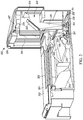
- FIG. 14 illustrates a side view of the barcode reader 200 showing an example vertical field of view 1400 of the camera 107 when the barcode reader 200 is implemented with the insert 702 of FIG. 7 .
- the insert 702 carries the camera 107 in the portrait orientation.
- the vertical field of view 1400 is approximately 70°.
- the vertical field of view 1400 can be different (e.g., between 45° and 100°).
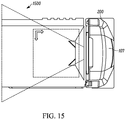
- FIG. 15 illustrates a top plan view of the barcode reader 200 showing an example horizontal field of view 1500 of the camera 107 when the barcode reader 200 is implemented with the insert 702 .
- the insert 702 carries the camera 107 in the portrait orientation.
- the horizontal field of view 1500 is approximately 53°.
- the horizontal field of view 1500 can be different (e.g., between 45° and 100°).
- the above disclosed apparatus, methods and articles of manufacture enable barcode readers to be field upgraded with cameras using example inserts.
- the inserts may be referred to as adapters.
- the inserts are structured to hold the cameras in a desired orientation.
- the insert may hold the camera in a landscape orientation or a portrait orientation or any other desired position.
- the example bar code readers include means for enabling a change of an orientation of a camera between a first orientation and a second orientation, where the means includes a receptacle that is configured to alternatively receive one of a first field-installable insert or a second field-installable insert.
- the camera carried by the field-installable inserts is structured to obtain non-barcode data.
- a includes . . . a”, “contains . . . a” does not, without more constraints, preclude the existence of additional identical elements in the process, method, article, or apparatus that comprises, has, includes, contains the element.
- the terms “a” and “an” are defined as one or more unless explicitly stated otherwise herein.
- the terms “substantially”, “essentially”, “approximately”, “about” or any other version thereof, are defined as being close to as understood by one of ordinary skill in the art, and in one non-limiting embodiment the term is defined to be within 10%, in another embodiment within 5%, in another embodiment within 1% and in another embodiment within 0.5%.
- the term “coupled” as used herein is defined as connected, although not necessarily directly and not necessarily mechanically.
- a device or structure that is “configured” in a certain way is configured in at least that way, but may also be configured in ways that are not listed.
- processors such as microprocessors, digital signal processors, customized processors and field programmable gate arrays (FPGAs) and unique stored program instructions (including both software and firmware) that control the one or more processors to implement, in conjunction with certain non-processor circuits, some, most, or all of the functions of the method and/or apparatus described herein.
- processors or “processing devices” such as microprocessors, digital signal processors, customized processors and field programmable gate arrays (FPGAs) and unique stored program instructions (including both software and firmware) that control the one or more processors to implement, in conjunction with certain non-processor circuits, some, most, or all of the functions of the method and/or apparatus described herein.
- FPGAs field programmable gate arrays
- unique stored program instructions including both software and firmware
- an embodiment can be implemented as a computer-readable storage medium having computer readable code stored thereon for programming a computer (e.g., comprising a processor) to perform a method as described and claimed herein.
- Examples of such computer-readable storage mediums include, but are not limited to, a hard disk, a CD-ROM, an optical storage device, a magnetic storage device, a ROM (Read Only Memory), a PROM (Programmable Read Only Memory), an EPROM (Erasable Programmable Read Only Memory), an EEPROM (Electrically Erasable Programmable Read Only Memory) and a Flash memory.
Abstract
Description
Claims (15)
Priority Applications (2)
| Application Number | Priority Date | Filing Date | Title |
|---|---|---|---|
| US16/167,159 US10691905B2 (en) | 2018-10-22 | 2018-10-22 | Field-upgradable barcode readers |
| US16/908,409 US11048897B2 (en) | 2018-10-22 | 2020-06-22 | Field-upgradable barcode readers |
Applications Claiming Priority (1)
| Application Number | Priority Date | Filing Date | Title |
|---|---|---|---|
| US16/167,159 US10691905B2 (en) | 2018-10-22 | 2018-10-22 | Field-upgradable barcode readers |
Related Child Applications (1)
| Application Number | Title | Priority Date | Filing Date |
|---|---|---|---|
| US16/908,409 Continuation US11048897B2 (en) | 2018-10-22 | 2020-06-22 | Field-upgradable barcode readers |
Publications (2)
| Publication Number | Publication Date |
|---|---|
| US20200125811A1 US20200125811A1 (en) | 2020-04-23 |
| US10691905B2 true US10691905B2 (en) | 2020-06-23 |
Family
ID=70280703
Family Applications (2)
| Application Number | Title | Priority Date | Filing Date |
|---|---|---|---|
| US16/167,159 Active US10691905B2 (en) | 2018-10-22 | 2018-10-22 | Field-upgradable barcode readers |
| US16/908,409 Active US11048897B2 (en) | 2018-10-22 | 2020-06-22 | Field-upgradable barcode readers |
Family Applications After (1)
| Application Number | Title | Priority Date | Filing Date |
|---|---|---|---|
| US16/908,409 Active US11048897B2 (en) | 2018-10-22 | 2020-06-22 | Field-upgradable barcode readers |
Country Status (1)
| Country | Link |
|---|---|
| US (2) | US10691905B2 (en) |
Cited By (2)
| Publication number | Priority date | Publication date | Assignee | Title |
|---|---|---|---|---|
| US11048897B2 (en) * | 2018-10-22 | 2021-06-29 | Zebra Technologies Corporation | Field-upgradable barcode readers |
| US11843744B2 (en) | 2021-01-21 | 2023-12-12 | Datalogic Usa, Inc. | Image-reading device having configurable multi-mode illumination sequences and monochrome color image capture sequences and related methods |
Families Citing this family (1)
| Publication number | Priority date | Publication date | Assignee | Title |
|---|---|---|---|---|
| US20230316018A1 (en) * | 2022-03-31 | 2023-10-05 | Zebra Technologies Corporation | Illumination System Optimized for Vertical and Horizontal Slot Scanners |
Citations (3)
| Publication number | Priority date | Publication date | Assignee | Title |
|---|---|---|---|---|
| US8727218B1 (en) * | 2013-01-03 | 2014-05-20 | Symbol Technologies, Inc. | Symmetric customer side scanner for bioptic rear tower |
| US9022288B2 (en) * | 2012-09-05 | 2015-05-05 | Metrologic Instruments, Inc. | Symbol reading system having predictive diagnostics |
| US9275263B2 (en) * | 2008-11-26 | 2016-03-01 | Symbol Technologies, Llc | Imaging reader with plug-in imaging modules for electro-optically reading indicia |
Family Cites Families (2)
| Publication number | Priority date | Publication date | Assignee | Title |
|---|---|---|---|---|
| US10460574B2 (en) * | 2015-05-12 | 2019-10-29 | Symbol Technologies, Llc | Arrangement for and method of processing products at a workstation upgradeable with a camera module for capturing an image of an operator of the workstation |
| US10691905B2 (en) * | 2018-10-22 | 2020-06-23 | Zebra Technologies Corporation | Field-upgradable barcode readers |
-
2018
- 2018-10-22 US US16/167,159 patent/US10691905B2/en active Active
-
2020
- 2020-06-22 US US16/908,409 patent/US11048897B2/en active Active
Patent Citations (3)
| Publication number | Priority date | Publication date | Assignee | Title |
|---|---|---|---|---|
| US9275263B2 (en) * | 2008-11-26 | 2016-03-01 | Symbol Technologies, Llc | Imaging reader with plug-in imaging modules for electro-optically reading indicia |
| US9022288B2 (en) * | 2012-09-05 | 2015-05-05 | Metrologic Instruments, Inc. | Symbol reading system having predictive diagnostics |
| US8727218B1 (en) * | 2013-01-03 | 2014-05-20 | Symbol Technologies, Inc. | Symmetric customer side scanner for bioptic rear tower |
Cited By (2)
| Publication number | Priority date | Publication date | Assignee | Title |
|---|---|---|---|---|
| US11048897B2 (en) * | 2018-10-22 | 2021-06-29 | Zebra Technologies Corporation | Field-upgradable barcode readers |
| US11843744B2 (en) | 2021-01-21 | 2023-12-12 | Datalogic Usa, Inc. | Image-reading device having configurable multi-mode illumination sequences and monochrome color image capture sequences and related methods |
Also Published As
| Publication number | Publication date |
|---|---|
| US20200125811A1 (en) | 2020-04-23 |
| US11048897B2 (en) | 2021-06-29 |
| US20200320260A1 (en) | 2020-10-08 |
Similar Documents
| Publication | Publication Date | Title |
|---|---|---|
| US11048897B2 (en) | Field-upgradable barcode readers | |
| AU2020277149B2 (en) | Bi-optic barcode reader | |
| US10921177B1 (en) | Barcode reader with off-platter detection | |
| US20200380224A1 (en) | Barcode readers including illumination assemblies with different color lights | |
| US11861994B2 (en) | Compact self-checkout kiosks | |
| US11823152B2 (en) | Self-checkout kiosk | |
| US11922267B2 (en) | Barcode reader with off-platter detection | |
| US11461574B2 (en) | Bioptic reader assembly with video upgrade module | |
| US20230169285A1 (en) | Bioptic Barcode Reader with Multiple Imaging Devices | |
| EP2941761B1 (en) | Symmetric customer side scanner for bioptic rear tower | |
| US8844815B2 (en) | Method of adjusting pointing directions of multiple cameras in barcode scanner | |
| US20130068839A1 (en) | Method of and apparatus for imaging targets by utilizing multiple imaging modules with on-board local microprocessors | |
| US20210142016A1 (en) | Systems and methods for selectively initiating identification sessions | |
| US20230316019A1 (en) | Single Plane Slot Scanner Support for Vision Camera Configurations | |
| US11960963B2 (en) | Barcode readers with biometric user identification | |
| US20150347798A1 (en) | Point-of-transaction workstation for, and method of, imaging sheet-like targets |
Legal Events
| Date | Code | Title | Description |
|---|---|---|---|
| FEPP | Fee payment procedure |
Free format text: ENTITY STATUS SET TO UNDISCOUNTED (ORIGINAL EVENT CODE: BIG.); ENTITY STATUS OF PATENT OWNER: LARGE ENTITY |
|
| AS | Assignment |
Owner name: ZIH CORP., ILLINOIS Free format text: ASSIGNMENT OF ASSIGNORS INTEREST;ASSIGNORS:DRZYMALA, MARK;BARKAN, EDWARD;HANDSHAW, DARRAN MICHAEL;SIGNING DATES FROM 20181022 TO 20181029;REEL/FRAME:047338/0177 |
|
| AS | Assignment |
Owner name: ZEBRA TECHNOLOGIES CORPORATION, ILLINOIS Free format text: MERGER;ASSIGNOR:ZIH CORP.;REEL/FRAME:048470/0848 Effective date: 20181220 |
|
| AS | Assignment |
Owner name: JPMORGAN CHASE BANK, N.A., AS COLLATERAL AGENT, NEW YORK Free format text: SECURITY INTEREST;ASSIGNOR:ZEBRA TECHNOLOGIES CORPORATION;REEL/FRAME:049674/0916 Effective date: 20190701 |
|
| STPP | Information on status: patent application and granting procedure in general |
Free format text: PUBLICATIONS -- ISSUE FEE PAYMENT VERIFIED |
|
| STCF | Information on status: patent grant |
Free format text: PATENTED CASE |
|
| AS | Assignment |
Owner name: JPMORGAN CHASE BANK, N.A., NEW YORK Free format text: SECURITY INTEREST;ASSIGNORS:ZEBRA TECHNOLOGIES CORPORATION;LASER BAND, LLC;TEMPTIME CORPORATION;REEL/FRAME:053841/0212 Effective date: 20200901 |
|
| AS | Assignment |
Owner name: LASER BAND, LLC, ILLINOIS Free format text: RELEASE OF SECURITY INTEREST - 364 - DAY;ASSIGNOR:JPMORGAN CHASE BANK, N.A.;REEL/FRAME:056036/0590 Effective date: 20210225 Owner name: TEMPTIME CORPORATION, NEW JERSEY Free format text: RELEASE OF SECURITY INTEREST - 364 - DAY;ASSIGNOR:JPMORGAN CHASE BANK, N.A.;REEL/FRAME:056036/0590 Effective date: 20210225 Owner name: ZEBRA TECHNOLOGIES CORPORATION, ILLINOIS Free format text: RELEASE OF SECURITY INTEREST - 364 - DAY;ASSIGNOR:JPMORGAN CHASE BANK, N.A.;REEL/FRAME:056036/0590 Effective date: 20210225 |
|
| AS | Assignment |
Owner name: JPMORGAN CHASE BANK, N.A., NEW YORK Free format text: SECURITY INTEREST;ASSIGNOR:ZEBRA TECHNOLOGIES CORPORATION;REEL/FRAME:056471/0906 Effective date: 20210331 |
|
| MAFP | Maintenance fee payment |
Free format text: PAYMENT OF MAINTENANCE FEE, 4TH YEAR, LARGE ENTITY (ORIGINAL EVENT CODE: M1551); ENTITY STATUS OF PATENT OWNER: LARGE ENTITY Year of fee payment: 4 |