US1069145A - Lubricator-pump. - Google Patents
Lubricator-pump. Download PDFInfo
- Publication number
- US1069145A US1069145A US50291209A US1909502912A US1069145A US 1069145 A US1069145 A US 1069145A US 50291209 A US50291209 A US 50291209A US 1909502912 A US1909502912 A US 1909502912A US 1069145 A US1069145 A US 1069145A
- Authority
- US
- United States
- Prior art keywords
- piston
- stroke
- port
- pump
- eccentric
- Prior art date
- Legal status (The legal status is an assumption and is not a legal conclusion. Google has not performed a legal analysis and makes no representation as to the accuracy of the status listed.)
- Expired - Lifetime
Links
- 230000033001 locomotion Effects 0.000 description 10
- 238000010276 construction Methods 0.000 description 4
- 239000000314 lubricant Substances 0.000 description 3
- 238000013459 approach Methods 0.000 description 2
- 238000010586 diagram Methods 0.000 description 2
- 241001255830 Thema Species 0.000 description 1
- 230000001133 acceleration Effects 0.000 description 1
- 230000001419 dependent effect Effects 0.000 description 1
- 230000003292 diminished effect Effects 0.000 description 1
- 239000012530 fluid Substances 0.000 description 1
- 239000007788 liquid Substances 0.000 description 1
Images

Classifications
-
- F—MECHANICAL ENGINEERING; LIGHTING; HEATING; WEAPONS; BLASTING
- F16—ENGINEERING ELEMENTS AND UNITS; GENERAL MEASURES FOR PRODUCING AND MAINTAINING EFFECTIVE FUNCTIONING OF MACHINES OR INSTALLATIONS; THERMAL INSULATION IN GENERAL
- F16N—LUBRICATING
- F16N13/00—Lubricating-pumps
- F16N13/02—Lubricating-pumps with reciprocating piston
- F16N13/06—Actuation of lubricating-pumps
- F16N13/10—Actuation of lubricating-pumps with mechanical drive
Definitions
- Patented nag. 53,1913 Patented nag. 53,1913.
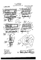
- Figure l is a. vertical orossisectont through the. lubricator in the plane of one ofthe. pumps;
- Fig,.2 is a. ⁇ sectional elevationview, at r1 lo.
- Figs. 4 5, 6 and 7 are diagrams illustrating the operationlof the pump; and
- Figs. Sendit-'are respectively eA section and elevation.r of' thereversing mechanism Aristhe tank. or.
- the piston, E. is driven I the medium of aconnecting rodl
- the piston F is driven from thesame. or adjacent eccentric throughv the medium of a ⁇ bell crank leven J one arm of which is bifurcated to embrace the eccentric while the other'r arm engages the end'. of t e piston.
- the pistons are arranged. in parallel; relation, it is obvious that. theV point of reversed of one will be substantially at ⁇ midst-roke oi the other, by reason ofthe change in direction ofthe move.- ment ⁇ effected by the bell crank,
- the lubricant is conducted from the bottom of the. tank ⁇ to the piston, F through the. riser tube K, which communicateswith a pont L ⁇ controlled. by thepiston E This is. placed in communication with a port leading to the cylinder ofv the piston F gby an annular groove N1 in the. piston E,
- the piston E is at the beginning of its suction stroke and the piston F is at mid-stroke, being about to open theport Q and to con- A nect the same kwith the passage Q2, while in Fig. 7 the l'piston E is at the beginningof its propelling stroke and the plston F isA again at mid-stroke and' about to open the' port Q3 and place the same in communication with the discharge conduit R.
- the lubricant is first pumped to the sight feed and then propelled to the point to be lubricated through the operation of positive mechanism, and
- I preferably provide means forV altering the effective stroke of the iston F. This, as shown, is accomplished y forming the piston F hollow and inserting a plug or piston S in the Vend thereof so lasvto have'a limited travel therewith.
- the amount of travel is determined by an adjustable stop T, preferably'a rotatable cam, mounted upon the casing A. When this cam is adjusted in one position it will hold the plug S stationary and consequently the whole stroke of the piston F will be eifective, but, by adjusting the stop away from the plug a limited'lost motion will Vbe provided and the effective stroke of the piston diminished a corresponding amount.
- the mechanism is timed to operatethe plungers E and F in proper sequence when the shaft B is rotated in one direction, but upon the reversal of this shaft the parts will be thrown out of time. This is for the reason that t-he pistons E and F are in eifect90 apart-'in their engagement with the eccentric:
- the pin U is at the end of the segmental slot, which will driveboth eccentrics in thev direction of the 'arrowfsaid eccentrics being in registration witheach other.
- the pin U will iirst travel to the opposite end of the segmental slot, and the two eccentrics will bespaced 180 apart, asillusdischarged by the other.
- a Huid feed device two c linders and pistons therein, an actuating evice there-v or, ports and passages arranged so that the pistons Aact as valves for each other, and means for varyin the amount of feed.
- a sight feed a sight feed, reservoir, a pump which takes liquid from the reservoir and delivers it to the sight feed, a pump which takes the Huid from the sight-feed land delivers it to the discharge, the piston of each pump acting as the .valve for the other.
- V y a sight feed, reservoir, a pump which takes liquid from the reservoir and delivers it to the sight feed, a pump which takes the Huid from the sight-feed land delivers it to the discharge, the piston of each pump acting as the .valve for the other.
Landscapes
- Engineering & Computer Science (AREA)
- General Engineering & Computer Science (AREA)
- Mechanical Engineering (AREA)
- Reciprocating Pumps (AREA)
Description
W. L. KENFIELD. LUBRIGATOR PUMP.
APPLICATION FILED JUNE 18, 1909.
. Patented Aug. 5, 1913.
i if
[fz Ven, for
lfizfzesses W z/Zzzzm. ]enf dd.
y ma? aohle v which unrTnD sTaTns re TENT 'onirica mm1-ms L.' xnnnrnLn, onnn'rnorr, monteert, AssIeNon 'ro DET-noir Luna-reuma company, or Bernois?, MICHIGAN, A oorona'rron or momenti.
LUBRIGAmRv-PUMP'.
Themas;
Patented nag. 53,1913.
Application ledune 18, 1309; Serial No. 502,912.
To aZZ whom t mcycrmocm Be it known that I, WILLIAM L. FIELD, a citizen of the. United States. of America, residing at Detroit, in the county of. Wayne, and Stateof Michi an, have i11- vented certain. new andl use l. Improve-V ments in. LuhricatoriPumps, of which vthe following is a speciiication, reference being had therein tothe accompanying drawings. The. invention. consists in*` a construction embodyingtwo pumps, each having a cylf inder and piston, the piston of one pump acting as the valve for controlling the othen pump, whereby the necessity for anyv chockvalvesor other parts than the two-v pistons themselves -to control. the. How. of the oil. is obviated; in the construction ofY the actuatdevicos. for the istons. whereby they may be properly timedl. toperform this. doufimcton; in. the construction. of. this actuating device. whereby the timing ofV the valves; may. be automatically adjusted. regardlessgef.; the direction. inwhich the driveshaft for. the pistons is turned', and further. in. the constructionand arrangement in combination: ofthe. various parts, all as more .fully heinater described. and particularly pointed out inthe claims.
In the drawings, Figure l is a. vertical orossisectont through the. lubricator in the plane of one ofthe. pumps; Fig,.2 is a.` sectional elevationview, at r1 lo. Fig, Bis anelevationoit .opposite endet Eig, 2; Figs. 4 5, 6 and 7 are diagrams illustrating the operationlof the pump; and Figs. Sendit-'are respectively eA section and elevation.r of' thereversing mechanism Aristhe tank. or. 'casing for the lubricant, in which is ecran ed a Series ofv mechanical numnsall operate a-corumonshaft E, in turnisdriventhrough the medium oi a wor-ergearing.- C extending out fromthecasing, All of. the pumps ol-the-scriesare of thewme construction,y and are arranged side hy side along the. shaft B, fuero which they are driven. Eachv comprise.s` a pail? of pistons E, and. E operating; in. ported. cylinders. preferably struction issuchmhateach piston periorms the double functionAL off. aplunger for pro polling the oil and a valve for controlling the ponts of' the cylinder for the other pist N.. Thus, the piston- E operates to raise from an eccentric H through t angles to Fig,
f which. registers from adrive shaft D the-port MA and a'port 0, which latterfconf :nects with sight feed. cant through formedin anintegralcasting G.. The con-` the' oil from the tank and, propel it to the sight feed', the` piston-E coperating in the control of the ports, while. the latter pumps the. oil from.- the sight feed' and. propels it. to the -.part to belubricated through the. cooperation of the pistonvv Fi controlling its ports. In order that these pistonsmay each properly perform this double function, it. is esirable that the movement. should be retarded during. a. portion of the stroke and that the timeof' greatest retardation of one p1stonwould'A correspond.l with the ltime of the greatest acceleration of'V the other. piston. 'Thisl have accomplished by driving` each `'piston from. an eccentric on the shaft B,
which imparts a simple harmonic movement, and through intermediate connections the movements ofthe pistons` are. thrown. out of phase. Specifically., the piston, E. is driven I the medium of aconnecting rodl, and the piston F is driven from thesame. or adjacent eccentric throughv the medium of a` bell crank leven J one arm of which is bifurcated to embrace the eccentric while the other'r arm engages the end'. of t e piston. As the pistons are arranged. in parallel; relation, it is obvious that. theV point of reversed of one will be substantially at` midst-roke oi the other, by reason ofthe change in direction ofthe move.- ment` effected by the bell crank,
. The lubricant is conducted from the bottom of the. tank` to the piston, F through the. riser tube K, which communicateswith a pont L` controlled. by thepiston E This is. placed in communication with a port leading to the cylinder ofv the piston F gby an annular groove N1 in the. piston E,
saidports as said piston E. approaches oneend of its stroke, while at. the opposite end of its stroke.A the same with groove N establishes communicationbetween the conduit. P, leading to the The conduit P discharges lubrithe sight feed chamber P into a well P2, whichconnects with a. port Q in the cylinder of the piston. E. This port is connected with a poet Q. in the piston F as the latter approaches-one endl ol its stroke, and through which the lubricantisconveyed to a passage Q2 leading to a .port Q3 in the cylinder of' the piston E, and as the piston E approaches the opposite` end of. its. stroke a port R therein establishes communication between the port Q3 and a passage R leading to the discharge condult.
The sequence of operatic-ns is illustratedl in the diagrams, Figs.` 4 to 7, inclusive. I'n Fig. 4 the piston AF is jat the beginning of its suction stroke, and the'piston which is at mid-stroke, is about to uncover the port L and place the same in communication'with the port M, the direction of movement of each piston being indicated by the arrows. In Fig. 5 the piston F is at the beginning of its return stroke and the piston E is again at mid-stroke, having closed the port L and being about to open the port O. lIn Fig. 6 the piston E is at the beginning of its suction stroke and the piston F is at mid-stroke, being about to open theport Q and to con- A nect the same kwith the passage Q2, while in Fig. 7 the l'piston E is at the beginningof its propelling stroke and the plston F isA again at mid-stroke and' about to open the' port Q3 and place the same in communication with the discharge conduit R. Thus in the complete operation the lubricant is first pumped to the sight feed and then propelled to the point to be lubricated through the operation of positive mechanism, and
not dependent upon check valves.
To vary t-he amount of feed, I preferably provide means forV altering the effective stroke of the iston F. This, as shown, is accomplished y forming the piston F hollow and inserting a plug or piston S in the Vend thereof so lasvto have'a limited travel therewith. The amount of travel is determined by an adjustable stop T, preferably'a rotatable cam, mounted upon the casing A. When this cam is adjusted in one position it will hold the plug S stationary and consequently the whole stroke of the piston F will be eifective, but, by adjusting the stop away from the plug a limited'lost motion will Vbe provided and the effective stroke of the piston diminished a corresponding amount.
The mechanism is timed to operatethe plungers E and F in proper sequence when the shaft B is rotated in one direction, but upon the reversal of this shaft the parts will be thrown out of time. This is for the reason that t-he pistons E and F are in eifect90 apart-'in their engagement with the eccentric:
when rotated in one `direction and 270 apart in the rotation in the opposite direction.
Thus to properly time the mechanism when i reversely driven there must be a shifting of the eccentric which operates one of the plungers through an' angle of 180". l I have accomplished this shifting automatically by forming the eccentric of two members H and H', one of which is driven from the other through the medium of a lost motion connection, and this connection is such that upon reversal the driving eccentric can move 180 beim it imparts motion to the other member. Thus, as shown, the eccentric HI', which actuates the piston E, is'loose upon the shaft Bv and is coupled ,to the eccentric H by thepin Us'ecured t the 'eccentric H, which engages a segmental slot V. When the parts arein` the position shown in Fig. 1 the pin U is at the end of the segmental slot, which will driveboth eccentrics in thev direction of the 'arrowfsaid eccentrics being in registration witheach other. On the other hand, when the direction of rotation is re versed the pin Uwill iirst travel to the opposite end of the segmental slot, and the two eccentrics will bespaced 180 apart, asillusdischarged by the other.
What I claim as my invention is:
1. In a Huid feed device two c linders and pistons therein, an actuating evice there-v or, ports and passages arranged so that the pistons Aact as valves for each other, and means for varyin the amount of feed.
2. In a fluid eed device, a sight feed, reservoir, a pump which takes liquid from the reservoir and delivers it to the sight feed, a pump which takes the Huid from the sight-feed land delivers it to the discharge, the piston of each pump acting as the .valve for the other. V y
3. The combination of a frame, and two" cylinders and pistons therein, ofv anfinlet and'outlet port for each cylinder, such ports v'tion for re-adjusting said mechanism into correspondingly timed relation.v
5.. In a lubricatonethe combination of a piston, a valve, a rotary member for actuating the same, and intermediate mechanism' timed for operation by. rotation in one direction, said mechanism including a lost motion connection whereby upon reversal of the direction of ,rotationitffwill automatically readjust itself inta-.correspondingly timed relation.
6. In a lubricatorfthe combination of a piston, a valve, arotary member fory actuating the same, and intermediate connections for said piston and valve timed for operation in one direction, one of said connections having a 10st mot-ion whereby upon reversal 5 of the direction of rotation it will remain inactive during a movement of 180.
7 In a pump, two cylinders and the pistons therein, a drive shaft, an eccentric thereon in two parts for driving the pistons, 10 one part loose on fixed, a connection the shaft and the other for causing the two eccentrics to move as one in the forward direction, and for permitting the accent-riesv to
Priority Applications (1)
| Application Number | Priority Date | Filing Date | Title |
|---|---|---|---|
| US50291209A US1069145A (en) | 1909-06-18 | 1909-06-18 | Lubricator-pump. |
Applications Claiming Priority (1)
| Application Number | Priority Date | Filing Date | Title |
|---|---|---|---|
| US50291209A US1069145A (en) | 1909-06-18 | 1909-06-18 | Lubricator-pump. |
Publications (1)
| Publication Number | Publication Date |
|---|---|
| US1069145A true US1069145A (en) | 1913-08-05 |
Family
ID=3137383
Family Applications (1)
| Application Number | Title | Priority Date | Filing Date |
|---|---|---|---|
| US50291209A Expired - Lifetime US1069145A (en) | 1909-06-18 | 1909-06-18 | Lubricator-pump. |
Country Status (1)
| Country | Link |
|---|---|
| US (1) | US1069145A (en) |
-
1909
- 1909-06-18 US US50291209A patent/US1069145A/en not_active Expired - Lifetime
Similar Documents
| Publication | Publication Date | Title |
|---|---|---|
| US1874010A (en) | Pump | |
| US932033A (en) | Johannes krone | |
| US1840864A (en) | Power transmission apparatus | |
| US1238939A (en) | Oil-pump. | |
| US1069145A (en) | Lubricator-pump. | |
| US2687118A (en) | Fluid motor embodying power units operatively connected to a crankshaft | |
| US2766590A (en) | Fluid pressure system for motivating a reciprocating load | |
| US2096907A (en) | Fluid pump | |
| US762055A (en) | Variable-speed transmission and regulator or brake. | |
| US3220316A (en) | Slow-running reversible piston-engines operating on compressed fluid or the like | |
| US2550966A (en) | Variable displacement pump control mechanism | |
| US1348738A (en) | Power-transmission apparatus | |
| US603173A (en) | Motor | |
| US1312962A (en) | Valveless pump | |
| US1157415A (en) | Fluid-power-transmitting apparatus for vehicles. | |
| CA1060811A (en) | Method and system of lubricating a plurality of compressed air operated devices | |
| US1508806A (en) | Pump with variable output and constant number of strokes | |
| US1078889A (en) | Pump for lubricating systems. | |
| US2682837A (en) | Variable displacement hydraulic torque converter | |
| US574915A (en) | Lough | |
| US3892072A (en) | Variable speed hydraulic transmission | |
| US2448467A (en) | Power intensifier two stage uniform flow | |
| US1449537A (en) | Means for pumping fluids | |
| US822685A (en) | Lubricating apparatus. | |
| US1673410A (en) | Lubricating device |