US1069138A - Flying-machine. - Google Patents
Flying-machine. Download PDFInfo
- Publication number
- US1069138A US1069138A US73008512A US1912730085A US1069138A US 1069138 A US1069138 A US 1069138A US 73008512 A US73008512 A US 73008512A US 1912730085 A US1912730085 A US 1912730085A US 1069138 A US1069138 A US 1069138A
- Authority
- US
- United States
- Prior art keywords
- machine
- arch
- supporting surface
- supporting
- air
- Prior art date
- Legal status (The legal status is an assumption and is not a legal conclusion. Google has not performed a legal analysis and makes no representation as to the accuracy of the status listed.)
- Expired - Lifetime
Links
- 230000005484 gravity Effects 0.000 description 7
- IWEDIXLBFLAXBO-UHFFFAOYSA-N dicamba Chemical compound COC1=C(Cl)C=CC(Cl)=C1C(O)=O IWEDIXLBFLAXBO-UHFFFAOYSA-N 0.000 description 5
- 239000004744 fabric Substances 0.000 description 3
- 239000000463 material Substances 0.000 description 2
- 150000001875 compounds Chemical class 0.000 description 1
- 238000010276 construction Methods 0.000 description 1
- 230000002939 deleterious effect Effects 0.000 description 1
- 230000000881 depressing effect Effects 0.000 description 1
- 230000003028 elevating effect Effects 0.000 description 1
- 230000002708 enhancing effect Effects 0.000 description 1
- 230000002452 interceptive effect Effects 0.000 description 1
- 230000004048 modification Effects 0.000 description 1
- 238000012986 modification Methods 0.000 description 1
- 238000009877 rendering Methods 0.000 description 1
- 238000005728 strengthening Methods 0.000 description 1
Images
Classifications
-
- B—PERFORMING OPERATIONS; TRANSPORTING
- B64—AIRCRAFT; AVIATION; COSMONAUTICS
- B64C—AEROPLANES; HELICOPTERS
- B64C39/00—Aircraft not otherwise provided for
- B64C39/08—Aircraft not otherwise provided for having multiple wings
Definitions
- This invention relates to flying machines or aerodromes, and has for its object to provide a structure of this character which shall be safe, light, and at the same time of maximum strength, shall have a low center of gravity, and which shall, when in the air, and particularly when descending with the power of the engine cut off, possess great stability and parachute efliciency.
- a further object of the invention is to improve such machines in certain other details of construction.
- One ob ect of the invention is to locate the load below the aero-supporting surface, stifien the structure. as a whole, and support the lateral portions or wings of the machine, and this I accomplish by providing an inverted arch under the machine, which arch is rigidly secured at its ends to the outer portions of the wings, and is also tied at intervals along its length to the structure, preferably by means of vertical stanchions.
- the in verted arch is preferably tied to the structure by prolonging the vertical stanchions separating the aerial supporting surfaces from each other, until such stanchions reach and are united to the framework of the arch.
- This arch is preferably a frame-work so constructed that it in no way interferes with the supply of air to the under side of the lower supporting surface of the structure, though such frame-work may be, and preferably is, provided with a reticulated or net-work covering, which affords means for carrying the motor, the aviator, passengers and other freight, well below the aero-- supporting surfaces are employed) is the one to which the air offers the main resistance which prevents the machine from falling too rapidly, the other supporting surfaces of the machine being largely robbed of the supply of air whose resistance would otherwise enable them toperform this supporting function to the highest degree. This results in two objectionable features.
- I provide a central opening through the lower supporting surface, so as to permit a free upward movement of the air caught under the lower supporting surface during the descent of the machine, which air thus passes to the under part of the upper supporting surface.
- the result of this is cooperation of the two aerosupporting surfaces, and that the main and most efficient resistance to the downward movement of the machine is that offered by the upper supporting surface.
- This places the main supporting surface well above the center of gravity of the machine, and particularly is this the case when such machine is provided with the inverted arch carrying the engine, aviator and other weight below the lower supporting surface, with the con- .sequent low center of gravity.
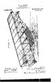
- Fig. 1 is a front elevation of F1g..1
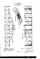
- Fig. '3 1s a plan view of the lower supporting surface
- Fig. 4 is a perspective view of a different form of supporting arch from that shown in Fig. 1.
- 1 is an upper supporting surface, and 2 a lower supporting surface, which surfaces are composed .of a suitable frame-work covered by any preferred or suitable material impervious to air. surfaces 1 and 2--a're connected vat suitable intervals at the front and the rear of'themachine by means ofstanchionsB,
- Beneath the lower supporting surface 2,1 provide a structure for stiffening and supporting the win s of the machine, which structure is here s own as in the form of an inverted arch 6.
- this arch isstruck on the lines of a compound curve, as shown in Figs. v1 and 2, in which only the middle portion of the arch is approximately parallel with thesupporting surfaces above it, but if desired, the arch may receive the 1 ;chine, and the lateral'portions i, 7 are inclined more sharply upward, and joined at their extremities to. theouter portions.
- I also provide openings, as 10, 10, through the net-work, conveniently located for dropping-bombs therethroligh, this affording a more convenient and eflicient means of dropping a bomb from the machine :than for the operator to reach out over the forward or rearward edge ofthe'machine.
- the machine may be mountedv upon any suitable chassis.- or other corresponding means for supporting it on the ground. As here shown, this takesthe form of a chassis 11, and'thestanchions 3, 3, on elther slde of the medial portion of the machine are preferably extended downward past the.
- the inverted arch affords an efiicient means for bracing or strengthening the wing portions of the structure, and preventing the same from breaking off, thus rendering possible all increased lateral extension of said portions; that it affords means for carrying the main weight imposed upon the machine at the very lowest point, thereby materially lowering the center of gravity of the machine as a whole; and in short, that it increases the safety of the machine by lowering the center of gravity to the maximum, strengthens the structure, permits increased wing-surface, affords large space for passengers, freight, etc., with great parachute efficiency, while "at the same time it leaves an unobstructed view and with greater freedom of personal movement.
- Any suitable steering, elevating and depressing rudders, properly supported, may be any suitable steering, elevating and depressing rudders, properly supported,
- What is claimed is 1.
- a flying machine a plurality of superposed supporting surfaces, a supporting inverted arch structure under the lowermost supporting surface, means for securing the ends of the arch to the ends of the lowermost supporting surface, and means for rigidly securing said arch and supporting surfaces together.
- a flying machine a plurality of super-posed supporting surfaces, a supporting inverted arch structure under the lowermost supporting surface, means for securing the ends of the arch to the ends of the lowermost supporting surface, and stanchions rigidly securing said arch and supporting surfaces together.
- a flying machine a plurality of super-posed supporting surfaces, a supporting structure under the lowermost supporting surface, said structure being in the form of an open inverted arch on which the operating mechanism and the aviator are carried, means securingthe ends of said arch to the ends of the lowermost supporting surface, and means intermediate the ends of said arch rigidly securing said arch and supporting surfaces together.
Landscapes
- Engineering & Computer Science (AREA)
- Aviation & Aerospace Engineering (AREA)
- Tents Or Canopies (AREA)
Description
H. L. E. JOHNSON.
FLYING MACHINE. urmonmn nLnn nov. 7. 1912.
Patented Aug. 5, 1913.
2 snnnwe-snnm 1.
Allame WITN SSES G 3 .M. M W6 H. L. E. JOHNSON. FLYING MACHINE.
APPLICATION FILED NOV. 7, 1912.
Patented Aug. 5, 1913.
2 SHEETS-SHEET 2.
WITNESSES fiNTOR 08A 0. 5552 I Mn Imp 6auv, @km g I HENRY L. E. JOHNSON, OF WASHINGTON, ZDISTLRICYL OF COLUMBIA.
FLYING-MACHINE.
Specification of Letters Patent.
Patented Aug. 5,1913.
Application filed November 7, 1912. Serial No. 730,085.
To all whom it may concern:
Be it known that I, HENRY L. E. JOH N- SON, of Washington, District of Columbia, have invented a new and useful Improvement in Flying-Machines, which inventionis fully set forth in the following specification.
This invention relates to flying machines or aerodromes, and has for its object to provide a structure of this character which shall be safe, light, and at the same time of maximum strength, shall have a low center of gravity, and which shall, when in the air, and particularly when descending with the power of the engine cut off, possess great stability and parachute efliciency.
A further object of the invention is to improve such machines in certain other details of construction.
One prominent point of weakness in flying machines as heretofore constructed (in which the supporting surfaces extend for considerable distances on each side of the medial fore and aft line of the machine, and have a limited dimension from front to rear), resides in the fact that the lateral or wing portions of the machine are liable to be. broken off from the central portion of the structure. This is due to the extended length of the wings laterally, and the consequent everage.
One ob ect of the invention is to locate the load below the aero-supporting surface, stifien the structure. as a whole, and support the lateral portions or wings of the machine, and this I accomplish by providing an inverted arch under the machine, which arch is rigidly secured at its ends to the outer portions of the wings, and is also tied at intervals along its length to the structure, preferably by means of vertical stanchions. Where a plurality of supporting surfaces are employed, the in verted arch is preferably tied to the structure by prolonging the vertical stanchions separating the aerial supporting surfaces from each other, until such stanchions reach and are united to the framework of the arch. This arch is preferably a frame-work so constructed that it in no way interferes with the supply of air to the under side of the lower supporting surface of the structure, though such frame-work may be, and preferably is, provided with a reticulated or net-work covering, which affords means for carrying the motor, the aviator, passengers and other freight, well below the aero-- supporting surfaces are employed) is the one to which the air offers the main resistance which prevents the machine from falling too rapidly, the other supporting surfaces of the machine being largely robbed of the supply of air whose resistance would otherwise enable them toperform this supporting function to the highest degree. This results in two objectionable features. In the ,first place, it provides the greatest support (resistance to the falling action) for themachine at a point very little, if any, above its center of gravity, and therefore materially lessens or'diminishes or interferes with the stability of the machine as a whole. This results in a tendency of the machine to pitch forward, or rearward, or to either side, lose equilibrium and control, and fall to the earth. The second deleterious result of this action is found in the fact that only one of the supporting surfaces (the lower one) oifersma terial resistance to the downward movement of the machine, the supporting surface or surfaces above the lower surface being rendered inefficient or less effective than they should be for this purpose.
By the present invention, I provide a central opening through the lower supporting surface, so as to permit a free upward movement of the air caught under the lower supporting surface during the descent of the machine, which air thus passes to the under part of the upper supporting surface. The result of this is cooperation of the two aerosupporting surfaces, and that the main and most efficient resistance to the downward movement of the machine is that offered by the upper supporting surface. This places the main supporting surface well above the center of gravity of the machine, and particularly is this the case when such machine is provided with the inverted arch carrying the engine, aviator and other weight below the lower supporting surface, with the con- .sequent low center of gravity. In order to i still further increase the stability of the machine, to lessen or prevent air slip over the lateral ends; and to direct lateral currents of air inward and under the supporting surfaces thereof, I deflect the outer ends of --the Supporting surfaces downward at a suitable angle, the downwardly deflected portions, however, being rigid with the main supporting surface. 1o
receivlng a varlet-y of mechanical expres- The inventive idea involved is capable of tive view of one form which my invention may assume; 2 is a front elevation of F1g..1; Fig. '3 1s a plan view of the lower supporting surface; and Fig. 4 is a perspective view of a different form of supporting arch from that shown in Fig. 1.
reference numerals Referring tothesedrawings, in which like indicate like partsthroughout the several views, 1 is an upper supporting surface, and 2 a lower supporting surface, which surfaces are composed .of a suitable frame-work covered by any preferred or suitable material impervious to air. surfaces 1 and 2--a're connected vat suitable intervals at the front and the rear of'themachine by means ofstanchionsB,
.. and at the extreme ends of each of the surfaces 1 and 2, there are provided downwardly inclined parts 4. v The frame of the upper 'surface 1 is covered throughout its extentwith air-impervious fabric, while the lowersurface 2 is so covered throughout the greater portion of its extent, but there is provided means whereby air may pass from the under side of this surface upward into the space between the two surfaces 1 and 2. In the particular form of the invention herein shown, such means, are in the form of a central space or opening 5 in the frame-work of the lower surface, which is not covered with air-impervious fabric, but is left entirely open and unobstructed, to the end that air may freely pass therethrough upward to the under part of the surface 1..
Beneath the lower supporting surface 2,1 provide a structure for stiffening and supporting the win s of the machine, which structure is here s own as in the form of an inverted arch 6. Preferably, this arch isstruck on the lines of a compound curve, as shown in Figs. v1 and 2, in which only the middle portion of the arch is approximately parallel with thesupporting surfaces above it, but if desired, the arch may receive the 1 ;chine, and the lateral'portions i, 7 are inclined more sharply upward, and joined at their extremities to. theouter portions. of
Y the wings of the lower supporting surface.
Whichever form of arch is employed, the ends thereof are firmly secured to the outer portions of the frame-work of the wings or supporting surfaces, and also at intervals along the arch the same is securely trussed to the frame-work of the supporting surfaces, this preferably being accomplished by extending the stanchions 3 downward and securing them firmly to the arch, as clearly illustrated in Figs. 1 and 2. This arch 6 in some instances may be covered with an airlmpervious fabric, but in the present instance it is shown as an open frame-work,
and does not interfere with the free access of the air from beneath the same to the under side of the lowermost supporting surface 2. As a means, however, of enabling the engine, the aviator, passengers or freight to be carried on such arch, there may be, and preferably'is, provided anopen network 8, composed of heavy woven wire or other suitable material, which would afford a support for .the engine, aviator, etc., without interfering with the free upward passage of the air therethrough to the under side of the lower supporting surface. This capability of the net-work is indicated in the drawings, by showingrthe engine 9 in position on such net-work. I also provide openings, as 10, 10, through the net-work, conveniently located for dropping-bombs therethroligh, this affording a more convenient and eflicient means of dropping a bomb from the machine :than for the operator to reach out over the forward or rearward edge ofthe'machine.
The machine may be mountedv upon any suitable chassis.- or other corresponding means for supporting it on the ground. As here shown, this takesthe form of a chassis 11, and'thestanchions 3, 3, on elther slde of the medial portion of the machine are preferably extended downward past the.
arch 6, and secured to the chassis 11, as at 12. This-however, is not essential, as any other suitable means for properly securing the chassis or other ground-supportto the inverted arch may be employed. Of course, it'will be understood that the frame-work of r the machine as a whole and the inverted arch and the lower supporting surface are suitably trussed and stiffened by the usual or any preferred form of truss-wires, such as 13, 14, thereby serving to still further stifi'en the structure.
It will be seen that the inverted arch, affords an efiicient means for bracing or strengthening the wing portions of the structure, and preventing the same from breaking off, thus rendering possible all increased lateral extension of said portions; that it affords means for carrying the main weight imposed upon the machine at the very lowest point, thereby materially lowering the center of gravity of the machine as a whole; and in short, that it increases the safety of the machine by lowering the center of gravity to the maximum, strengthens the structure, permits increased wing-surface, affords large space for passengers, freight, etc., with great parachute efficiency, while "at the same time it leaves an unobstructed view and with greater freedom of personal movement. Furthermore, it will be seen that, by reason of the opening 5 through the lower supporting surface, the efficiency of the upper supporting surface during the downward movement of the machine is n'laintained at .the maximum, thus placing the main point of support at the highest possible point above the center of gravity of the structure as a whole, and to a high degree enhancing or adding to the stability of such structure. It will also be seen that the action of the rigid, downwardly inclined portions 4 of the supporting surfaces is to direct currents of air inward under the respective supporting surfaces, and thus still further add to the stability of the entire structure.
While, for the purpose of clearness in explaining the invent-ion, the same has been herein described with considerable detail, it is to be expressly understood that the inven tion is not limited to the several details so specifically described, but that it is capable of variation and modification in form and proportions within the terms of the claims hereto appended.
Any suitable steering, elevating and depressing rudders, properly supported, may
be employed, but as these do not form any part of the present invention, they are not shown herein.
What is claimed is 1. In a flying machine a plurality of superposed supporting surfaces, a supporting inverted arch structure under the lowermost supporting surface, means for securing the ends of the arch to the ends of the lowermost supporting surface, and means for rigidly securing said arch and supporting surfaces together.
.2. In a flying machine a plurality of super-posed supporting surfaces, a supporting inverted arch structure under the lowermost supporting surface, means for securing the ends of the arch to the ends of the lowermost supporting surface, and stanchions rigidly securing said arch and supporting surfaces together.
3. In a flying machine, a plurality of super-posed supporting surfaces, a supporting structure under the lowermost supporting surface, said structure being in the form of an open inverted arch on which the operating mechanism and the aviator are carried, means securingthe ends of said arch to the ends of the lowermost supporting surface, and means intermediate the ends of said arch rigidly securing said arch and supporting surfaces together.
In testimony whereof I have signed this specification in the presence of two subscribing witnesses.
HENRY L. E. JOHNSON.
Witnesses:
S. T. CAMERON, W. 15. KERKAM. v
Priority Applications (1)
| Application Number | Priority Date | Filing Date | Title |
|---|---|---|---|
| US73008512A US1069138A (en) | 1912-11-07 | 1912-11-07 | Flying-machine. |
Applications Claiming Priority (1)
| Application Number | Priority Date | Filing Date | Title |
|---|---|---|---|
| US73008512A US1069138A (en) | 1912-11-07 | 1912-11-07 | Flying-machine. |
Publications (1)
| Publication Number | Publication Date |
|---|---|
| US1069138A true US1069138A (en) | 1913-08-05 |
Family
ID=3137376
Family Applications (1)
| Application Number | Title | Priority Date | Filing Date |
|---|---|---|---|
| US73008512A Expired - Lifetime US1069138A (en) | 1912-11-07 | 1912-11-07 | Flying-machine. |
Country Status (1)
| Country | Link |
|---|---|
| US (1) | US1069138A (en) |
-
1912
- 1912-11-07 US US73008512A patent/US1069138A/en not_active Expired - Lifetime
Similar Documents
| Publication | Publication Date | Title |
|---|---|---|
| US2973923A (en) | Helicopter construction | |
| CS197339B2 (en) | Parachute | |
| US1069138A (en) | Flying-machine. | |
| US1157636A (en) | Aircraft. | |
| US1861596A (en) | Wing for airplanes | |
| US2206910A (en) | Heavy load parachute device | |
| US1627614A (en) | Aerial landing harp eor aeroplanes | |
| US1413258A (en) | Flying machine | |
| US1885570A (en) | Aircraft | |
| US1715284A (en) | Aeroplane | |
| US1035103A (en) | Aeroplane. | |
| US1095548A (en) | Flying-machine. | |
| US990424A (en) | Flying-machine. | |
| US1226521A (en) | Flying-machine. | |
| US1012540A (en) | Flying-machine. | |
| US1268779A (en) | Hydroaeroplane. | |
| US1021496A (en) | Flying-machine. | |
| US1300927A (en) | Aeroplane. | |
| US981367A (en) | Air-craft. | |
| US1027322A (en) | Flying-machine. | |
| US1246015A (en) | Aeroplane. | |
| US1850890A (en) | Aircraft | |
| US1533312A (en) | Location of benzine tanks in aeroplanes | |
| US1117155A (en) | Flying-machine. | |
| US1431646A (en) | Aeroplane and flying machine with flapping wings |