US10691203B2 - Image sound output device, image sound output method and image sound output program - Google Patents
Image sound output device, image sound output method and image sound output program Download PDFInfo
- Publication number
- US10691203B2 US10691203B2 US15/955,941 US201815955941A US10691203B2 US 10691203 B2 US10691203 B2 US 10691203B2 US 201815955941 A US201815955941 A US 201815955941A US 10691203 B2 US10691203 B2 US 10691203B2
- Authority
- US
- United States
- Prior art keywords
- sound
- output
- image
- gaze
- point
- Prior art date
- Legal status (The legal status is an assumption and is not a legal conclusion. Google has not performed a legal analysis and makes no representation as to the accuracy of the status listed.)
- Active, expires
Links
Images


Classifications
-
- G—PHYSICS
- G06—COMPUTING OR CALCULATING; COUNTING
- G06F—ELECTRIC DIGITAL DATA PROCESSING
- G06F3/00—Input arrangements for transferring data to be processed into a form capable of being handled by the computer; Output arrangements for transferring data from processing unit to output unit, e.g. interface arrangements
- G06F3/01—Input arrangements or combined input and output arrangements for interaction between user and computer
- G06F3/011—Arrangements for interaction with the human body, e.g. for user immersion in virtual reality
- G06F3/013—Eye tracking input arrangements
-
- G—PHYSICS
- G06—COMPUTING OR CALCULATING; COUNTING
- G06F—ELECTRIC DIGITAL DATA PROCESSING
- G06F3/00—Input arrangements for transferring data to be processed into a form capable of being handled by the computer; Output arrangements for transferring data from processing unit to output unit, e.g. interface arrangements
- G06F3/01—Input arrangements or combined input and output arrangements for interaction between user and computer
- G06F3/03—Arrangements for converting the position or the displacement of a member into a coded form
- G06F3/0304—Detection arrangements using opto-electronic means
-
- G—PHYSICS
- G06—COMPUTING OR CALCULATING; COUNTING
- G06F—ELECTRIC DIGITAL DATA PROCESSING
- G06F3/00—Input arrangements for transferring data to be processed into a form capable of being handled by the computer; Output arrangements for transferring data from processing unit to output unit, e.g. interface arrangements
- G06F3/01—Input arrangements or combined input and output arrangements for interaction between user and computer
- G06F3/048—Interaction techniques based on graphical user interfaces [GUI]
- G06F3/0484—Interaction techniques based on graphical user interfaces [GUI] for the control of specific functions or operations, e.g. selecting or manipulating an object, an image or a displayed text element, setting a parameter value or selecting a range
- G06F3/04842—Selection of displayed objects or displayed text elements
-
- G—PHYSICS
- G06—COMPUTING OR CALCULATING; COUNTING
- G06F—ELECTRIC DIGITAL DATA PROCESSING
- G06F3/00—Input arrangements for transferring data to be processed into a form capable of being handled by the computer; Output arrangements for transferring data from processing unit to output unit, e.g. interface arrangements
- G06F3/16—Sound input; Sound output
- G06F3/165—Management of the audio stream, e.g. setting of volume, audio stream path
-
- G—PHYSICS
- G11—INFORMATION STORAGE
- G11B—INFORMATION STORAGE BASED ON RELATIVE MOVEMENT BETWEEN RECORD CARRIER AND TRANSDUCER
- G11B27/00—Editing; Indexing; Addressing; Timing or synchronising; Monitoring; Measuring tape travel
- G11B27/02—Editing, e.g. varying the order of information signals recorded on, or reproduced from, record carriers
- G11B27/031—Electronic editing of digitised analogue information signals, e.g. audio or video signals
-
- G—PHYSICS
- G11—INFORMATION STORAGE
- G11B—INFORMATION STORAGE BASED ON RELATIVE MOVEMENT BETWEEN RECORD CARRIER AND TRANSDUCER
- G11B27/00—Editing; Indexing; Addressing; Timing or synchronising; Monitoring; Measuring tape travel
- G11B27/10—Indexing; Addressing; Timing or synchronising; Measuring tape travel
- G11B27/34—Indicating arrangements
-
- A—HUMAN NECESSITIES
- A61—MEDICAL OR VETERINARY SCIENCE; HYGIENE
- A61B—DIAGNOSIS; SURGERY; IDENTIFICATION
- A61B3/00—Apparatus for testing the eyes; Instruments for examining the eyes
- A61B3/10—Objective types, i.e. instruments for examining the eyes independent of the patients' perceptions or reactions
- A61B3/113—Objective types, i.e. instruments for examining the eyes independent of the patients' perceptions or reactions for determining or recording eye movement
Definitions
- the present disclosure relates to an image sound output device, an image sound output method and an image sound output program.
- the corneal reflection technique is known as one of gaze detection technologies.
- the corneal reflection technique applies infrared light that is emitted from light sources to a subject, images, with cameras, the eyes of the subject to which the infrared light is applied, detects the positions of the pupils with respect to corneal reflection images that are reflected images of the light sources on the cornel surfaces, and detects the gaze of the subject.
- a gaze detection device using such a corneal reflection technique causes a display screen to display a still image or a moving image as a stimulus to a subject and causes a sound output device to output sound as the stimulus.
- Patent Document 1 Japanese Laid-open Patent Publication No. 2016-187589 A
- the above-described gaze detection device requires a configuration to efficiently adjust the timing of changing the mode in which sound is output. Furthermore, not only gaze detection devices but image sound output devices that output images and sounds require a configuration to efficiently adjust the timing of changing the mode in which sound is output.
- An image sound output device includes a display screen configured to display an image on a display screen, a sound output device configured to output a sound, a gaze point detector configured to detect a position of a point of gaze of an observer observing the display screen, an area setting unit configured to set a specific area on part of the display screen or of the image, a determination unit configured to, when the specific area is set on the display screen or the image, determine whether the point of gaze is within the specific area on the basis of a result of the detecting the position of the point of gaze, and an output controller configured to cause the display screen to display the image and cause the sound output device to output the sound and, when it is determined that the point of gaze is within the specific area, adjust at least a mode in which the sound is output.
- An image sound outputting method includes causing a display screen to display an image, causing a sound output device to output a sound, detecting a position of a point of gaze of an observer observing the display screen, setting a specific area on part of the display screen or of the image, when the specific area is set on the display screen or the image, determining whether the point of gaze is within the specific area on the basis of a result of the detecting the position of the point of gaze, and when it is determined that the point of gaze is within the specific area, adjusting at least a mode in which the sound is output.
- a non-transitory computer readable recording medium storing therein an image sound output program causes a computer to execute a process including causing a display screen to display an image, causing a sound output device to output a sound, detecting a position of a point of gaze of an observer observing the display screen, setting a specific area on part of the display screen or of the image, when the specific area is set on the display screen or the image, determining whether the point of gaze is within the specific area on the basis of a result of the detecting the position of the point of gaze, and when it is determined that the point of gaze is within the specific area, adjusting at least a mode in which the sound is output.
- FIG. 1 is a perspective view schematically illustrating an exemplary gaze detection device that is an image sound output device according to an embodiment
- FIG. 2 is a diagram illustrating an exemplary hardware configuration of the gaze detection device according to the embodiment
- FIG. 3 is a functional block diagram illustrating an exemplary gaze detection device according to the embodiment
- FIG. 4 is a schematic diagram for explaining a method of calculating positional data about the center of a corneal curvature according to the embodiment
- FIG. 5 is a schematic diagram for explaining the method of calculating positional data about the center of the corneal curvature according to the embodiment
- FIG. 6 is a schematic diagram for explaining an exemplary calibration process according to the embodiment.
- FIG. 7 is a schematic diagram for explaining an exemplary point-of-gaze detection process according to the embodiment.
- FIG. 8 is a table representing exemplary data that is stored in a storage unit
- FIG. 9 is a table representing exemplary data that is stored in the storage unit.
- FIG. 10 is a table representing exemplary data that is stored in the storage unit
- FIG. 11 is a timing chart indicating the timing of starting and ending display of an image and the timing of starting and ending output of a sound in association with each other;
- FIG. 12 is a timing chart indicating the timing of starting and ending display of an image and the timing of starting and ending output of a sound in association with each other;
- FIG. 13 is a timing chart indicating the timing of starting and ending display of an image and the timing of starting and ending output of a sound in association with each other;
- FIG. 14 is a timing chart indicating the sets of timing of starting and ending display of images and the timing of starting and ending output of a sound in association with each other;
- FIG. 15 is a timing chart indicating the sets of timing of starting and ending display of images and the timing of starting and ending output of a sound in association with each other;
- FIG. 16 is a timing chart indicating the sets of timing of starting and ending display of images and the timing of starting and ending output of a sound in association with each other;
- FIG. 17 is a timing chart indicating the timing of starting and ending display of an image and the timing of starting and ending output of a sound in association with each other;
- FIG. 18 is a timing chart indicating the timing of starting and ending output of a sound and the volume in association with each other;
- FIG. 19 is a timing chart indicating the sets of timing of starting and ending output of sounds and the volume in association with each other;
- FIG. 20 is a diagram illustrating an exemplary image that is displayed on a display screen of a display device
- FIG. 21 is a flowchart illustrating operations of the gaze detection device
- FIG. 22 is a flowchart illustrating an exemplary gaze detection process and an exemplary image sound output control process according to the embodiment
- FIG. 23 is a flowchart illustrating an exemplary image sound output control process
- FIG. 24 is a flowchart illustrating another exemplary image sound output control process
- FIG. 25 is a flowchart illustrating another exemplary image sound output control process
- FIG. 26 is a flowchart illustrating another exemplary image sound output control process.
- FIG. 27 is a diagram illustrating an electronic terminal that is another exemplary image sound output device according to the embodiment.
- a direction parallel with a first axis of a given plane serves as an X-axis direction
- a direction parallel to a second-axis of a given plane orthogonal to the first axis serves as a Y-axis direction
- a direction parallel to a third axis orthogonal to the first axis and the second axis serves as a Z-axis direction.
- the given planes include X and Y planes.
- FIG. 1 is a perspective view schematically illustrating an exemplary gaze detection device 100 that is an image sound output device according to an embodiment.
- the gaze detection device 100 is used also as an evaluation device that evaluates a subject.
- the gaze detection device 100 includes a display device 101 , a sound output device 70 , a stereo camera device 102 and an illumination device 103 .
- the display device 101 includes a flat panel display, such as a liquid crystal display (LCD) or an organic electroluminescence display (OLED).
- the display device 101 includes a display screen 101 S.
- the display screen 101 S displays an image.
- the display screen 101 S is substantially parallel to the X-Y plane.
- the X-axis direction is the horizontal direction of the display screen 101 S
- the Y-axis direction is the vertical direction of the display screen 101 S
- the Z-axis direction is a depth direction orthogonal to the display screen 101 S.
- the sound output device 70 for example, includes a speaker and outputs sound for calling attention to the subject.
- the stereo camera device 102 includes a first camera 102 A and a second camera 102 B.
- the stereo camera device 102 is arranged below the display screen 101 S of the display device 101 .
- the first camera 102 A and the second camera 102 B are arranged in the X-axis direction.
- the first camera 102 A is arranged in the negative X-direction with respect to the second camera 102 B.
- Each of the first camera 102 A and the second camera 102 B includes an infrared camera that includes, for example, an optical system capable of transmitting infrared light having a wavelength of 850 [nm] and an imaging device capable of receiving the infrared light.
- the illumination device 103 includes a first light source 103 A and a second light source 103 B.
- the illumination device 103 is arranged below the display screen 101 S of the display device 101 .
- the first light source 103 A and the second light source 103 B are arranged in the X-axis direction.
- the first light source 103 A is arranged in the negative X-direction with respect to the first camera 102 A.
- the second light source 103 B is arranged in the positive X-direction with respect to the second camera 102 B.
- Each of the first light source 103 A and the second light source 103 B includes a light emitting diode (LED) light source that is able to emit near-infrared light having a wavelength of, for example, 850 [nm].
- the first light source 103 A and the second light source 103 B may be arranged between the first camera 102 A and the second camera 102 B.
- the illumination device 103 emits infrared light that is detection light to illuminate eyeballs 111 of the subject.
- the stereo camera device 102 images the eyeballs 111 with the second camera 102 B when the detection light that is emitted from the first light source 103 A is applied to the eyeballs 111 and images the eyeballs 111 with the first camera 102 A when the detection light that is emitted from the second light source 103 B is applied to the eyeballs 111 .
- a frame synchronization signal is output from at least one of the first camera 102 A and the second camera 102 B.
- the first light source 103 A and the second light source 103 B emit detection light according to the frame synchronization signal.
- the first camera 102 A acquires image data about the eyeballs 111 when the detection light that is emitted from the second light source 103 B is applied to the eyeballs 111 .
- the second camera 102 B acquires image data about the eyeballs 111 when the detection light that is emitted from the first light source 103 A is applied to the eyeballs 111 .
- the detection light When the detection light is applied to the eyeball 111 , part of the detection light reflects on a pupil 112 and the light from the pupils 112 is incident on the stereo camera device 102 .
- a corneal reflection image 113 that is a virtual image of the cornea is formed on the eyeball 111 and the light from the corneal reflection image 113 is incident on the stereo camera device 102 .
- Properly setting the relative positions among the first camera 102 A, the second camera 102 B, the first light source 103 A and the second light source 103 B lowers the intensity of the light incident on the stereo camera device 102 from the pupils 112 and increases the intensity of the light incident on the stereo camera device 102 from the corneal reflection images 113 .
- the image of the pupils 112 that is acquired by the stereo camera device 102 has low luminance and the image of the corneal reflection images 113 has high luminance.
- the stereo camera device 102 is able to detect the positions of the pupils 112 and the positons of the corneal reflection images 113 on the basis of the luminance of the acquired images.
- FIG. 2 is a diagram illustrating an exemplary hardware configuration of the gaze detection device 100 according to the embodiment.
- the gaze detection device 100 includes the display device 101 , the stereo camera device 102 , the illumination device 103 , a computer system 20 , an input/output interface device 30 , a drive circuit 40 , an output device 50 , an input device 60 and the sound output device 70 .
- the computer system 20 includes a computing processing device 20 A and a storage device 20 B.
- the computing processing device 20 A includes a microprocessor, such as a central processing unit (CPU).
- the storage device 20 B includes a memory, such as a read only memory (ROM) and a random access memory (RAM), or a storage.
- the computing processing device 20 A performs arithmetic processing according to a computer program 20 C that is stored in the storage device 20 B.
- the drive circuit 40 generates a drive signal and outputs the drive signal to the display device 101 , the stereo camera device 102 and the illumination device 103 .
- the drive circuit 40 supplies the image data about the eyeballs 111 that is acquired by the stereo camera device 102 to the computer system 20 via the input/output interface device 30 .
- the output device 50 includes a display device, such as a flat panel display.
- the output device 50 may include a printing device.
- the input device 60 is operated and thus generates input data.
- the input device 60 includes a keyboard or a mouse for computer systems.
- the input device 60 may include a touch sensor that is provided on the display screen of the output device 50 , which is the screen serving as the display device.
- the display device 101 and the computer system 20 are devices independent of one another.
- the display device 101 and the computer system 20 may be integrated with each other.
- the tablet personal computer may mount the computer system 20 , the input/output interface device 30 , the drive circuit 40 , and the display device 101 .
- FIG. 3 is a functional block diagram illustrating the exemplary gaze detection device 100 according to the embodiment.
- the input/output interface device 30 includes an input/output unit 302 .
- the drive circuit 40 includes a display device driver 402 that generates a drive signal for driving the display device 101 and outputs the drive signal to the display device 101 ; a first camera input/output unit 404 A that generates a drive signal for driving the first camera 102 A and outputs the drive signal to the first camera 102 A; a second camera input/output unit 404 B that generates a drive signal for driving the second camera 102 B and outputs the drive signal to the second camera 102 B; and a light source driver 406 that generates drive signals for driving the first light source 103 A and the second light source 103 B and outputs the drive signals to the first light source 103 A and the second light source 103 B.
- the first camera input/output unit 404 A supplies the image data about the eyeballs 111 that is acquired by the first camera 102 A to the computer system 20 via the input/output unit 302 .
- the second camera input/output unit 404 B supplies the image data about the eyeballs 111 that is acquired by the second camera 102 B to the computer system 20 via the input/output unit 302 .
- the computer system 20 controls the gaze detection device 100 .
- the computer system 20 includes a light source controller 204 , an image data acquisition unit 206 , an input data acquisition unit 208 , a position detector 210 , a center-of-curvature calculator 212 , a gaze point detector 214 , an area setting unit 216 , a determination unit 218 , a computing unit 220 , a storage unit 222 , an evaluator 224 and an output controller 226 .
- the functions of the computer system 20 are implemented by the computing processing device 20 A and the storage device 20 B.
- the light source controller 204 controls the light source driver 406 to control the operation mode of the first light source 103 A and the second light source 103 B.
- the light source controller 204 controls the first light source 103 A and the second light source 103 B such that the first light source 103 A and the second light source 103 B emit detection light at different sets of timing.
- the image data acquisition unit 206 acquires the image data about the eyeballs 111 of the subject, which is acquired by the stereo camera device 102 including the first camera 102 A and the second camera 102 B, from the stereo camera device 102 via the input/output unit 302 .
- the input data acquisition unit 208 acquires the input data, which is generated by operating the input device 60 , from the input device 60 via the input/output unit 302 .
- the position detector 210 detects positional data about the centers of the pupils on the basis of the image data about the eyeballs 111 that is acquired by the image data acquisition unit 206 .
- the position detector 210 then detects positional data about the centers of the corneal reflection on the basis of the image data about the eyeballs 111 that is acquired by the image data acquisition unit 206 .
- the centers of the pupils are the centers of the pupils 112 .
- the centers of the corneal reflections are the centers of the corneal reflection images 113 .
- the position detector 210 detects positional data about the center of the pupil and the positional data about the center of the corneal reflection with respect to each of the left and right eyeballs 111 of the subject.
- the center-of-curvature calculator 212 calculates the positional data about the centers of the corneal curvatures of the eyeballs 111 on the basis of the image data about the eyeballs 111 that is acquired by the image data acquisition unit 206 .
- the gaze point detector 214 detects positional data about the point of gaze of the subject on the basis of the image data about the eyeballs 111 that is acquired by the image data acquisition unit 206 .
- the positional data about the point-of-gaze refers to positional data about the intersections each between a gaze vector of the subject that is defined by the three-dimensional global coordinate system and the display screen 101 S of the display device 101 .
- the gaze point detector 214 detects a gaze vector of each of the left and right eyeballs 111 of the subject on the basis of the positional data about the center of the pupil and the positional data about the center of the corneal curvature that are acquired from the image data about the eyeball 111 . After the gaze vectors are detected, the gaze point detector 214 detects positional data about the points of gaze representing the intersections each between the gaze vector and the display screen 101 S.
- the area setting unit 216 sets a specific area on part of the display screen 101 S or of the image.
- the area setting unit 216 is able to set a specific area on each image that is displayed on the display screen 101 S.
- the area setting unit 216 is able to set specific areas in one or multiple areas in the image.
- the determination unit 218 determines whether the point of gaze is within the specific area on the basis of the positional data that is the result of detecting the position of the point of gaze and outputs data about the determination.
- the determination unit 218 determines whether the point of gaze is within the specific area, for example, at every given time.
- the given time may be, for example, a period (for example, every 50 [msec]) of the frame synchronization signal that is output from the first camera 102 A and the second camera 102 B.
- the computing unit 220 includes a management timer that manages a time during which an image is displayed and a time during which a sound is output and a detection timer that detects the time elapsing from the display of the image on the display screen 101 S.
- the computing unit 220 counts the number of times it is determined that the point of gaze is within the specific area.
- the computing unit 220 includes a counter that counts the number of times the determination about the specific area is made.
- the evaluator 224 calculates evaluation data about the subject.
- the evaluation data is data to evaluate the subject on the basis of the result of the detection by the gaze point detector.
- the storage unit 222 stores the image data about images to be displayed on the display screen 101 S, sound data of sounds to be output from the sound output device 70 , the determination data that is output from the determination unit 218 , and the evaluation data that is output from the evaluator 224 .
- the images to be displayed on the display screen 101 S includes still images and moving images.
- the storage unit 222 stores multiple sets of image data and multiple sets of sound data.
- the storage unit 222 stores data indicating sets of timing of starting and ending display of the images and timing data that indicates sets of timing of starting and ending output of the sounds.
- the storage unit 222 stores the image sound output program that causes a computer to execute a process including: causing a display screen to display an image; causing a sound output device to output a sound; detecting a position of a point of gaze of an observer observing the display screen; setting a specific area on part of the display screen or of the image; when the specific area is set on the display screen or the image, determining whether a point of gaze is within the specific area on the basis of a result of detecting the position of the point of gaze; and, when it is determined that the point of gaze is within the specific area, adjusting at least a mode in which a sound is output.
- the output controller 226 outputs data to at least one of the display device 101 , the output device 50 and the sound output device 70 .
- the output controller 226 causes the display screen 101 S to display an image.
- the output controller 226 selects a given one of multiple sets of image data and causes the display screen 101 S to display the image of the selected set of image data.
- the output controller 226 causes the sound output device 70 to output a sound.
- the output controller 226 selects a given one of multiple sets of sound data and causes the sound output device 70 to output the sound of the selected set of sound data.
- Adjusting the sound output mode includes any one of stopping or ending output of the sound, restarting the output the sound from the mode in which the output is stopped, and adjusting the volume of the sound. Adjusting the sound output mode further includes switching the sound that is selected.
- the output controller 226 controls the timing of ending display of the image displayed on the display screen 101 S. Controlling the timing of ending the display includes, for example, changing the timing of ending the display, which is the timing set in advance.
- the output controller 226 may cause the display screen 101 S or the output device 50 to display the position of the point of gaze of each of the left and right eyeballs 111 of the subject.
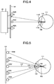
- FIG. 4 and FIG. 5 are schematic diagrams for explaining the method of calculating positional data about a corneal curvature center 110 according to the embodiment.
- FIG. 4 illustrates an example where the eyeballs 111 are illuminated with a single light source 103 C.
- FIG. 5 illustrates an example where the eyeballs 111 are illuminated with the first light source 103 A and the second light source 103 B.
- the light source 103 C is arranged between the first camera 102 A and the second camera 102 B.
- a pupil center 112 C is the center of the pupil 112 .
- a corneal reflection center 113 C is the center of the corneal reflection image 113 .
- the pupil center 112 C represents the center of the pupil at the time when the eyeball 111 is illuminated with the single light source 103 C.
- the corneal reflection center 113 C represents the center of the corneal reflection at the time when the eyeball 111 is illuminated with the single light source 103 C.
- the corneal reflection center 113 C is on a straight line connecting the light source 103 C and the corneal curvature center 110 .
- the corneal reflection center 113 C is positioned at a midpoint between the corneal surface and the corneal curvature center 110 .
- a corneal curvature radius 109 is the distance between the corneal surface and the corneal curvature center 110 .
- the positional data about the corneal reflection center 113 C is detected by the stereo camera device 102 .
- the corneal curvature center 110 is on a straight line connecting the light source 103 C and the corneal reflection center 113 C.
- the center-of-curvature calculator 212 calculates, as the positional data about the corneal curvature center 110 , the positional data representing that the distance from the corneal reflection center 113 C on the straight line is a given value.
- the given value is a value that is determined in advance from the value of a radius of curvature of a general cornea, etc., and is stored in the storage unit 222 .
- the first camera 102 A, the second light source 103 B, the second camera 102 B, and the first light source 103 A are arranged at positions that are symmetrical with respect to a straight line passing through the mid-position between the first camera 102 A and the second camera 102 B. It is considered that there is a virtual light source 103 V at the mid-position between the first camera 102 A and the second camera 102 B.
- a corneal reflection center 121 represents the center of the corneal reflection in an image of the eyeball 111 that is captured by the second camera 102 B.
- a corneal reflection center 122 represents the center of the corneal reflection in an image of the eyeball 111 that is captured by the first camera 102 A.
- a corneal reflection center 124 represents the center of the corneal reflection corresponding to the virtual light source 103 V.
- the positional data about the corneal reflection center 124 is calculated based on positional data about the corneal reflection center 121 and positional data about the corneal reflection center 122 , which are acquired by the stereo camera device 102 .
- the stereo camera device 102 detects positional data about the corneal reflection center 121 and positional data about the corneal reflection center 122 in the three-dimensional local coordinate system that is defined by the stereo camera device 102 .
- Camera calibration according to a stereo calibration method is performed on the stereo camera device 102 in advance to calculate a transformation parameter to transform the three-dimensional local coordinate system of the stereo camera device 102 into the three-dimensional global coordinate system.
- the transformation parameter is stored in the storage unit 222 .
- the center-of-curvature calculator 212 transforms the positional data about the corneal reflection center 121 and the positional data about the corneal reflection center 122 , which are acquired by the stereo camera device 102 , into sets of positional data in the three-dimensional global coordinate system by using the transformation parameter.
- the center-of-curvature calculator 212 calculates positional data about the corneal reflection center 124 in the three-dimensional global coordinate system on the basis of the positional data about the corneal reflection center 121 and the positional data about the corneal reflection center 122 , which are defined by the three-dimensional global coordinate system.
- the corneal curvature center 110 is on a straight line 123 connecting the virtual light source 103 V and the corneal reflection center 124 .
- the center-of-curvature calculator 212 calculates, as the positional data about the corneal curvature center 110 , the positional data representing that the distance from the corneal reflection center 124 on the straight line 123 is a given value.
- the given value is a value that is determined in advance from the value of a radius of a curvature of a general cornea, etc., and is stored in the storage unit 222 .
- the corneal curvature center 110 is calculated by using the same method as that for the case where there is a single light source.
- the corneal curvature radius 109 is the distance between the corneal surface and the corneal curvature center 110 . Accordingly, by calculating the positional data about the corneal surface and the positional data about the corneal curvature center 110 , the corneal curvature radius 109 is calculated.
- FIG. 6 is a schematic diagram for explaining an exemplary calibration process according to the embodiment.
- a target position 130 is set.
- the target position 130 is defined in the three-dimensional global coordinate system.
- the target position 130 is set, for example, at the center position of the display screen 101 S of the display device 101 .
- the target position 130 may be set at an end position of the display screen 101 S.
- the output controller 226 displays a target image on the target position 130 , which is set.
- a straight line 131 is a straight line connecting the virtual light source 103 V and the corneal reflection center 113 C.
- a straight line 132 is a straight line connecting the target position 130 and the pupil center 112 C.
- the corneal curvature center 110 is the intersection between the straight line 131 and the straight line 132 .
- the center-of-curvature calculator 212 is able to calculate positional data about the corneal curvature center 110 on the basis of positional data about the virtual light source 103 V, positional data about the target position 130 , positional data about the pupil center 112 C, and the positional data about the corneal reflection center 113 C.
- FIG. 7 is a schematic diagram for explaining the exemplary point-of-gaze detection process according to the embodiment.
- a gaze point 165 represents a point of gaze that is calculated from a corneal curvature center that is calculated by using the value of a radius of a general curvature.
- a gaze point 166 represents a point of gaze that is calculated from the center of the corneal curvature that is calculated by using a distance 126 that is calculated in the calibration process.
- the pupil center 112 C represents the center of the pupil that is calculated in the calibration process.
- the corneal reflection center 113 C represents the center of the corneal reflection that is calculated in the calibration process.
- a straight line 173 is a straight line connecting the virtual light source 103 V and the corneal reflection center 113 C.
- the corneal curvature center 110 is the position of the center of the corneal curvature that is calculated from the value of a radius of a general curvature.
- the distance 126 is the distance between the pupil center 112 C and the corneal curvature center 110 that is calculated by the calibration process.
- a corneal curvature center 110 H represents the position of the corneal curvature center after correction of the corneal curvature center 110 by using the distance 126 .
- the corneal curvature center 110 H is calculated from the fact that the corneal curvature center 110 is on the straight line 173 and the distance between the pupil center 112 C and the corneal curvature center 110 is the distance 126 . Accordingly, a line-of-sight 177 that is calculated in the case where the value of the curvature of the general radius is used is corrected to a line-of-sight 178 .
- the point of gaze on the display screen 101 S of the display device 101 is corrected from the gaze point 165 to the gaze point 166 .
- FIG. 8 is a table representing exemplary data that is stored in the storage unit 222 .
- FIG. 8 represents exemplary image data.
- the output controller 226 causes the display screen 101 S to display images 1 to 6 in turns for the corresponding reproduction times, respectively, according to the data stored in the storage unit 222 .
- the output controller 226 starts display of the image 1 and ends the display of the image 1 after the elapse of a time t 1 .
- the output controller 226 starts display of the image 2 after ending the display of the image 1 and ends the display of the image 2 after the elapse of a time 2 from the start of the display.
- the output controller 226 performs the process repeatedly on the images 3 to 6 and ends the process after ending the display of the image 6 .
- FIG. 9 is a table representing exemplary data that is stored in the storage unit 222 .
- FIG. 9 represents exemplary timing data representing the timing of starting and ending output of sound data.
- each set of sound data is stored as timing data in the storage unit 222 in association with an output start setting, an output end setting, and the number of times of output.
- the output start setting represents the content serving as a trigger to start output of sound data.
- the output end setting represents the content serving as a trigger to end output of the sound data.
- the number of times of output represents the number of times the sound data is output. For example, when the number of times of output is multiple times, that is, twice or more, it is indicated that the sound data is to be output repeatedly for multiple times.
- the output controller 226 starts output of a sound 1 .
- the output controller 226 ends the output of the sound 1 when ten seconds elapse from the start of the output of the sound 1 .
- the output controller 226 ends the process of the sound 1 without repetition.
- the output controller 226 starts the output of a sound 2 simultaneously with the start of the display of the image 2 .
- the output controller 226 ends the output of the sound 2 when five seconds elapse from the start of display of the image 3 after the display of the image 2 is ended.
- the output controller 226 ends the process of the sound 2 without repetition.
- FIG. 10 is a table representing exemplary data that is stored in the storage unit 222 .
- FIG. 10 represents exemplary volume data representing the volume of each sound.
- each set of sound data is stored in the storage unit 222 in association with the time elapsing from the start of the output and the volume, which is set.
- the output controller 226 keeps the volume at 50 until ten seconds elapses from the start of the output of the sound 1 , keeps the volume at 20 after ten seconds elapse, and keeps the volume at 50 after 20 seconds elapse, and keeps the volume at 20 after 30 seconds elapse.
- the output controller 226 keeps the volume at 0 until 0.5 second elapses from the start of the output of the sound 2 , keeps the volume at 10 after 0.5 second elapses, keeps the volume at 20 after one second elapses, and keeps the volume at 30 after 1.5 second elapses.
- FIGS. 11 to 17 are timing charts representing the sets of timing of starting and ending display of images and the sets of timing of starting and ending output of sounds in association with each other.
- Each of the patterns illustrated in FIGS. 11 and 17 are, for example, set in advance and stored in the storage unit 222 .
- Each of the following diagrams illustrates the exemplary images 1 to 3 as an exemplary case where multiple images are displayed in turns; however, the images are not limited thereto, and other images may be displayed.
- the sound 1 will be described as exemplary sound; however, the sound is not limited thereto, and another sound may be output.
- the timing chart of FIG. 11 represents the case where a time t 12 representing the timing of starting output of the sound 1 is “the time of the time point at which the given time elapses from the time t 11 to start display of the image 1 ” and a time t 13 representing the timing of ending output of the sound 1 is “the time point at which the sound 1 is output to the end”. In this case, it is possible to provide a time for the subject to focus on the image.
- the timing chart of FIG. 12 represents the case where a time t 21 representing the timing of starting output of the sound 1 is “simultaneous to the time to start display of the image 1 ” and a time t 22 representing the timing of ending output of the sound 1 is “the time point at which the sound 1 is output to the end”.
- the timing chart of FIG. 13 represents the case where a time t 32 representing the timing of starting output of the sound 1 is “the time of the time point at which a given time elapses from a time t 31 to start display of the image 1 ” and a time t 33 representing the timing of ending output of the sound 1 is “the time of the time point at which a given time elapses from the time t 32 to start the output”.
- the output ends even when the sound 1 is in the middle.
- the timing chart of FIG. 14 represents the exemplary case where the sound 1 is output over a display period for multiple images (the image 1 and the image 2 ).
- a time t 42 representing the timing of starting output of the sound 1 is “the time of the time point at which a given time elapses from a time t 41 to start display of the image 1 ”
- a time t 43 representing the timing of ending output of the sound 1 is “the time of the time point at which a given time elapses from the time to start display of the image 2 ”.
- the output ends even when the sound 1 is in the middle.
- a time t 52 representing the timing of starting output of the sound 1 is “the time of a time point at which a given time elapses from a time t 51 to start display of the image 1 ” and a time t 53 representing the timing of ending output of the sound 1 is “the time to start display of the image 2 ”.
- the output ends even when the sound 1 is in the middle.
- a time t 62 representing the timing of starting output of the sound 1 is “the time of a time point at which a given time elapses from a time t 61 to start display of the image 1 ” and a time t 63 representing the timing of ending output of the sound 1 is “the time to end the display of the image 2 (or the time to start display of the image 3 )”.
- the output ends even when the sound 1 is in the middle.
- the timing chart of FIG. 17 represents the exemplary case where the sound 1 is output repeatedly for multiple times.
- a time t 72 representing the timing of starting output of the sound 1 is “the time of a time point at which a given time elapses from a time t 71 to start display of the image 1 ”
- a time t 73 representing the timing of ending output of the sound 1 is “the time to end the display of the image 1 ”.
- the output ends even when the sound 1 is in the middle.
- FIGS. 18 and 19 are timing charts representing the sets of timing of starting and ending to output sounds and the volume in association with each other.
- Each of the patterns represented in FIG. 18 and FIG. 19 is, for example, set in advance and stored in the storage unit 222 .
- the volume at the time t 81 to start output of the sound is 0 and the volume at the time t 82 is V 85 .
- the volume is increased constantly between the time t 81 and the time t 82 .
- the volume is maintained at V 85 between the time t 82 and the time t 83 .
- the volume is reduced constantly from V 85 to 0 between the time t 83 to a time t 84 .
- the volume at a time t 91 to stat outputting the sound 1 is at V 95 and the volume reduces to V 96 lower than V 95 at a time t 92 and is maintained until the time t 93 .
- the volume is at V 95 again.
- the sound 2 is output at V 94 that is a volume larger than V 95 between the time t 92 and the time t 93 when the volume of the sound 1 reduces. As described above, it is possible to output different sounds simultaneously.
- the above-described timing of changing the volume is an example. It is thus possible to set another pattern different from the above-described pattern.
- FIG. 20 is a diagram illustrating an exemplary image that is displayed on the display screen 101 S of the display device 101 .
- the area setting unit 216 sets a specific area A on part of the display screen 101 S or of the image.
- the area setting unit 216 is able to set the specific area A in one or more spots on the display screen 101 S or the image.
- the specific area A is set in two spots; however, the embodiment is not limited thereto.
- two specific areas A are distinguished from one another below, they may be referred to as specific areas A 1 and A 2 .
- Each of the specific areas A is for example, circular; however, the embodiment is not limited thereto, and each of the specific areas A may be rectangular or may have another shape and the different specific areas A may have different shapes and sizes.
- the area setting unit 216 sets the specific areas A, for example, on the display screen 101 S distantly from one another.
- the output controller 226 displays objects M respectively in positions and areas corresponding to the specific areas A.
- the multiple objects M In the embodiment, for example, two objects M are displayed as the multiple objects M.
- the object M displayed in the specific area A 1 may be referred to as an object M 1
- the object M displayed in the specific area A 2 may be referred to as an object M 2 below.
- a pattern, etc. may be formed in the object M.
- the shape of the object M may match or different from the shape of the specific area A.
- FIG. 20 illustrates an exemplary point of gaze that is displayed by the output controller 226 as the result of measurement on the display screen 101 S.
- the output controller 226 prevents point of gaze from being displayed while the point of gaze of the subject is being detected.
- the positional data about the point of gaze is detected, for example, according to the period (for example, every 50 [msec]) of the frame synchronization signals that are output from the first camera 102 A and the second camera 102 B.
- the first camera 102 A and the second camera 102 B capture images in synchronization with each other.
- the determination unit 218 determines whether the point of gaze is within the specific area A on the basis of the positional data that is the result of the detection of the position of the point of gaze and outputs data about the detection.
- the determination unit 218 determines whether the point of gaze is within the specific area at every given time.
- the given time may be, for example, the period (for example, 50 [msec]) of the frame synchronization signals that are output from the first camera 102 A and the second camera 102 B.
- Adjusting the sound output mode includes any one of stopping or ending to output the sound, restarting output of the sound from the mode in which the output is stopped, and adjusting the volume of the sound. Adjusting the sound output mode includes switching the sound that is selected.
- the output controller 226 controls the timing of ending display of the image displayed on the display screen 101 S. Controlling the timing of ending the display includes, for example, changing the pre-set timing of ending the display.
- the output controller 226 is able to change the content of the control on the timing of adjusting the sound output mode and of ending display of the image according to within which of the specific areas A the point of gaze of the subject is. For example, when the point of gaze of the subject is within the specific area A 1 , it is possible to enable both adjustment of the sound output mode and control on the timing of ending display of the image. When the point of gaze of the subject is within the specific area A 2 , it is possible to enable only adjustment of the sound output mode.
- ending the sound output may be enabled as the adjustment of the sound output mode.
- switching the sound to be output to another sound may be enabled as the adjustment of the sound output mode.
- the content of the adjustment of the sound output mode and the content of the combination of the adjustment of the sound output mode and the control on the timing of ending display of the image which are described above, are an example only and thus the embodiment is not limited thereto. According to within which of the specific areas A the point of gaze is, a setting may be made to enable different content of the adjustment of the sound output mode and a setting may be made to enable different content of the combination between the adjustment of the sound output mode and the control on the timing of ending display of the image.
- FIG. 21 is a flowchart illustrating the operations of the gaze detection device 100 .
- the output controller 226 reads each of the sets of data represented in FIGS. 8 to 19 , that is, the setting data for images and sounds, the setting data for volume control, timing data, etc., from the storage unit 222 (step S 101 ).
- the computing unit 220 then resets the management timer for managing the times during each of which an image is displayed and the times during each of which a sound is output (step S 102 ).
- the gaze point detector 214 starts the point-of-gaze detection process to detect positional data about the point of gaze of the subject on the display screen 101 S of the display device 101 at every given sampling period (for example, 50 [ms]) (step S 103 ).
- step S 104 When the positional data is detected (NO at step S 104 ), the display screen 101 S is caused to display an image and the sound output device 70 is caused to output a sound to perform a given gaze detection process and, according to the result of gaze detection, an image sound output control process is performed (step S 105 ).
- the gaze detection process and the image sound output control process at step S 105 will be described below.
- step S 106 When the management timer does not reach the given time (NO at step S 106 ), the process at and after step S 103 is performed repeatedly.
- step S 107 point-of-gaze data that is obtained through the gaze detection process is evaluated (step S 107 ) and an evaluation value is output (step S 108 ).
- FIG. 22 is a flowchart illustrating an exemplary gaze detection process and an exemplary image sound output control process according to the embodiment.
- the output controller 226 causes the display screen 101 S to display an image for gaze detection (step S 201 ). With the image being displayed on the display screen 101 S, the gaze point detector 214 detects positional data about the point of gaze of the subject (step S 202 ).
- the determination unit 218 determines whether the point of gaze is within the specific area A (step S 203 ). When it is determined that the point of gaze is within the specific area A, the output controller 226 determines whether to change the sound output mode in the sound output device 70 (step S 204 ). When the output controller 226 determines to change the sound output mode (YES at step S 204 ), the output controller 226 changes the sound output mode in the sound output device 70 (step S 205 ). When the output controller 226 changes the sound output mode, the output controller 226 determines whether to change the image display mode (step S 206 ). When the output controller 226 determines to change the image display mode (YES at step S 206 ), the output controller 226 changes the image display mode (step S 207 ).
- the output controller 226 determines whether the display of the image ends (step S 208 ). On determining that the display of the image ends (YES at step S 208 ), the output controller 226 ends the process. On determining that display of the image does not end (NO at step S 208 ), the output controller 226 causes the process at and after step S 202 to be performed repeatedly.
- FIG. 23 is a flowchart illustrating the exemplary image sound output control process.
- FIG. 23 illustrates the exemplary case where the sound output ends according to the positional data about the point of gaze of the subject.
- the output controller 226 causes the display device 101 S to display an image for gaze detection (step S 301 ).
- the output controller 226 causes the display device 101 S to display a given image from among the images 1 to 6 that are stored in the storage unit 222 .
- the area setting unit 216 sets the specific area A on part of the display screen 101 S or the given image from among the images 1 to 6 .
- the computing unit 220 detects the time elapsing from the display of the image 1 by using the detection timer.
- the output controller 226 determines whether there is a sound to be output from the sound output device 70 (step S 302 ). At step S 302 , the output controller 226 detects whether there is, for example, a sound that is stored in association with “the image 1 ” from among the sounds that are stored in the storage unit 222 .
- the output controller 226 determines whether the time to start output of the sound is reached (step S 303 ). When the time to start output of the sound is not reached (NO at step S 303 ), the output controller 226 repeats the determination at step S 303 until the time to start the output is reached. On determining that the time to start output of the sound is reached (YES at step S 303 ), the output controller 226 starts the output of the sound (step S 304 ).
- the gaze point detector 214 acquires the positional data about the point of gaze of the subject (step S 305 ).
- the gaze point detector 214 detects positional data about the point of gaze of the subject on the display screen 101 S of the display device 101 at every given sampling period (for example, 50 [msec]).
- the determination unit 218 determines whether the point of gaze of the subject is within the specific area A in the image displayed on the display screen 101 S (step S 306 ). At step S 306 , the determination unit 218 determines whether the point of gaze is within the specific area A at every given time.
- the given time may be, for example, the period (for example, every 50 [msec]) of frame synchronization signals that are output from the first camera 102 A and the second camera 102 B.
- the output controller 226 changes the sound output mode. In this case, the output controller 226 , for example, ends the output of the sound (step S 308 ). At step S 308 , for example, even at the timing not in the timing data stored in the storage unit 222 , the output controller 226 ends the output of the sound by using the result of the determination by the determination unit 218 as a trigger. In the same manner, the sound output may be stopped (suspended).
- step S 306 when it is determined that the point of gaze of the subject is not within the specific area A, the output controller 226 determines whether there is a sound to be ended (step S 307 ).
- step S 307 the output controller 226 determines whether a sound is output at the time of step S 307 and, when a sound is output, determines that there is a sound to be ended. When no sound is output at the time of step S 307 , the output controller 226 determines that there is no sound to be output.
- the output controller 226 determines whether it is time to end the output of the sound (step S 309 ).
- the time to end the output is, for example, the time to end the sound in the timing chart (see FIGS. 11 to 17 ) that is stored in the storage unit 222 .
- the output controller 226 repeats the determination at step S 309 until the time to end the output is reached.
- the output controller 226 ends the output of the sound (step S 310 ).
- the output controller 226 determines whether it is time to end the display of the image on the display screen 101 S (step S 311 ). At step S 311 , the output controller 226 , for example, performs determination based on the management timer. On determining that it is time to end the display of the image (YES at step S 311 ), the output controller 226 ends the display of the image (step S 312 ). On determining that it is not time to end the display of the image (NO at step S 311 ), the output controller 226 causes the operations at and after step S 302 to be performed repeatedly.
- the output controller 226 determines whether all the images are displayed (step S 313 ). On determining that not all the images are displayed (NO at step S 313 ), the output controller 226 causes the operations at and after step S 301 to be performed repeatedly. On determining that all the images are displayed (YES t step S 313 ), the output controller 226 ends the image sound output process.
- FIG. 24 is a flowchart illustrating another exemplary image sound output control process.
- FIG. 24 illustrates the exemplary case where the sound to be output is switched according to the positional data about the point of gaze of the subject. As illustrated in FIG. 24 , when the sound to be output is switched according to the positional data about the point of gaze of the subject, only the process at step S 308 illustrated in FIG. 23 differs and the processes from step S 301 to step S 307 and from step S 309 to step S 313 are the same.
- the output controller 226 performs the process of switching the sound to be output instead of step S 308 (step S 314 ).
- the output controller 226 stops the output of the sound that is currently output and selects another sound instead of the sound that is currently output from among the multiple sounds stored in the storage unit 222 .
- the output controller 226 then causes the sound output device 70 to output the selected sound.
- the output controller 226 causes the process at and after step S 311 to be performed.
- the output controller 226 performs the process of changing the volume instead of step S 308 in the flowchart illustrated in FIG. 24 .
- the output controller 226 may select a sound corresponding to the specific area AX from among the allocated multiple sounds and cause the sound output device 70 to output the sound.
- the sound corresponding to the specific area A is not limited to one. Multiple sounds may be allocated and, when the determination unit 218 determines that the point of gaze is within the specific area A, the output controller 226 may select a sound from the allocated multiple sounds randomly and cause the sound output device 70 to output the sound.
- the output controller 226 may select the sound following the sound being reproduced according to the given order and, when the determination unit 218 determines that the point of gaze is within the specific area A 2 , the output controller 226 may select the sound being reproduced or the former sound according to the given order and cause the sound output device 70 to output the sound.
- FIG. 25 is a flowchart illustrating another exemplary image sound output control process.
- FIG. 25 illustrates the exemplary case where the sound output is started according to the positional data about the point of gaze of the subject.
- the processes at step S 401 , from step S 405 to step S 407 , and from step S 409 to step S 413 are the same as the processes at step S 301 , from step S 305 to step S 307 and from step S 309 to step S 313 in FIG. 23 .
- the process corresponding to steps S 302 to S 304 in FIG. 23 is not performed and the process at step S 405 is performed after step S 401 .
- the output controller 226 determines whether a sound is output (step S 414 ). On determining that no sound is output (NO at step S 414 ), the output controller 226 performs a process to start output of a sound (step S 415 ) and moves to step S 411 . On determining that a sound is output (YES at step S 414 ), the output controller 226 does not perform the process at step S 415 and moves to step S 411 . When the output of the sound is stopped (suspended), the output is restarted in the same manner. In this case, determination on whether the output of the sound is stopped is made as the process corresponding to step S 414 . A process of restarting the output of the sound is performed as a process corresponding to step S 415 .
- FIG. 26 is a flowchart illustrating another exemplary image sound output control process.
- FIG. 26 illustrates the exemplary case where, after the output of a sound is ended according to the positional data about the point of gaze of the subject, the timing of ending display of the image is controlled.
- the process from step S 501 to step S 513 is the same as the process from step S 301 to step S 313 in FIG. 23 .
- the output controller 226 ends the output of the sound as at step S 308 in FIG. 23 (step S 508 ).
- the output controller 226 determines whether to end the display of the image (step S 514 ).
- the output controller 226 moves to step S 512 to end the display of the image. In this case, even when the timing of ending the display, which is set previously, is not reached, the display of the image ends. Accordingly, the pre-set timing of ending the display is changed.
- the output controller 226 determines not to end the display of the image at step S 514 , the output controller 226 causes the process at and after step S 511 to be performed.
- the output controller 226 may perform the process at step S 514 without performing step S 508 . In this case, with the sound being output, the display of the image may be ended.
- the gaze detection device 100 includes the display screen 101 S that displays an image; the sound output device 70 that outputs a sound; the gaze point detector 214 that detects a position of a point of gaze of an observer observing the display screen 101 S; the area setting unit 216 that sets a specific area A on part of the display screen 101 S or of the image; the determination unit 218 that determines, when the specific area A is set on the display screen 101 S or the image, whether the gaze point P is within the specific area A on the basis of the result of the detection of the position of the gaze point P; and the output controller 226 that causes the display screen 101 S to display the image, causes the sound output device 70 to output a sound and, when it is determined that the gaze point P is within the specific area A, adjusts at least the sound output mode.
- adjusting the sound output mode includes any one of stopping or ending the output of the sound, restarting the output of the sound from the mode in which the output is stopped, and adjusting the volume of the sound.
- the output controller 226 selects a sound from among the multiple sounds and causes the sound output device 70 to output the sound and adjusting the sound output mode includes switching the sound that is selected. Accordingly, it is possible to adjust the sound output mode widely.
- the output controller 226 controls the timing of ending display of the image. Accordingly, it is possible to control the timing of ending display of the image according to the change of the sound output mode.
- controlling the timing of ending the display includes changing the pre-set timing of ending the display. Accordingly, it is possible to flexibly adjust the timing of ending display of an image according to the timing of ending output of a sound.
- FIG. 27 is a diagram illustrating an electronic terminal 500 that is another exemplary image sound output device according to the embodiment.
- the electronic terminal 500 includes portable electronic devices, such as tablet computers and smartphones.
- the electronic terminal 500 includes a housing 501 , a display screen 502 , an imaging device 503 , a sound output device 504 and a control device 505 .
- the housing 501 holds the display screen 502 , the imaging device 503 , the sound output device 504 and the control device 505 .
- the display screen 502 displays an image.
- the imaging device 503 is able to image the face of an observer observing the displays screen.
- the imaging device 503 is thus able to acquire image data about the eyeballs of the observer observing the display screen 502 .
- the sound output device 504 outputs a sound.
- the control device 505 controls operations of the display screen 502 , the imaging device 503 and the sound output device 504 .
- the control device 505 includes a microprocessor, such as a CPU, a memory, such as a ROM and a RAM, or a storage.
- the control device 505 includes a gaze point detector that detects the position of a point of gaze of the observer on the basis of the image data of the eyeballs of the observer imaged by the imaging device 503 ; an area setting unit that sets specific areas 502 a and 502 b on part of the image displayed on the display screen 502 ; a determination unit that, when the image on which the specific areas 502 a and 502 b are set is displayed on the display screen 502 , determines whether a gaze point P is within the specific area 502 a or 502 b on the basis of a result of detecting the position of the point of gaze; and an output controller that causes the display screen 502 to display an image, causes the sound output device 504 to output a sound, and, when it is determined that the gaze point P is within the specific area 502 a or 502 b , adjusts at least the sound output mode.
- a gaze point detector that detects the position of a point of gaze of the observer on the basis of the image data of the
- the control device 505 includes a storage unit.
- the storage unit stores, for example, data of images to be displayed on the display screen 502 and data of sounds to be output by the sound output device 504 .
- the storage unit further stores an image sound output program that causes a computer to execute: causing the display screen to display an image; causing the sound output device to output a sound; detecting the position of a point of gaze of the observer observing the display screen; setting a specific area on part of the image displayed on the display screen; when the image on which the specific area is set is displayed on the display screen, determining whether the point of gaze is within the specific area on the basis of a result of detecting the position of the point of gaze; and adjusting at least the sound output mode when it is determined that the point of gaze is within the specific area.
- the control device 505 causes the display screen 502 to display the image.
- the control device 505 sets the specific areas 502 a and 502 b on part of the image displayed on the display screen 502 . It is possible to set an appearance corresponding to the changed content of the sound output mode, which will be described below, for the appearance of the specific areas 502 a and 502 b .
- the control device 505 is able to display a mark to reproduce a sound on the specific area 502 a .
- the control device 505 is able to further display a mark to stop reproduction of the sound on the specific area 502 b.
- the control device 505 images the observer observing the display screen 502 with the imaging device 503 and acquires image data about the eyeballs of the observer. The control device 505 then detects the position of a point of gaze of the observer on the basis of the acquired image data.
- the control device 505 determines whether the detected point of gaze is within the specific area 502 a or 502 b . On determining that the gaze point P of the observer is within the specific area 502 a for example, the control device 505 performs, as the process of adjusting the sound output mode, a process of starting output of a sound or a process of restarting the output of the sound stopped from being output. On determining that the gaze point P of the observer is, for example, within the specific area 502 a , the control device 505 performs the process of stopping the output of the sound as the process of adjusting the sound output mode.
- the content of adjusting the sound output mode is not limited to the above-described one.
- Adjusting the sound output mode includes, for example, any one of stopping or ending the output of the sound, restarting the output of the sound from the mode in which the output is stopped, and adjusting the volume of the sound.
- adjusting the sound output mode includes switching the sound that is selected.
- control device 505 may control the timing of ending display of the image.
- the electronic terminal 500 that is the image sound output device that outputs an image and a sound
- the electronic terminal 500 that is the image sound output device that outputs an image and a sound
- step S 206 is integrated with step S 204 and step S 208 is integrated with step S 206 in FIG. 22 .
- Whether to change the sound output mode is determined at step S 204 and the image and sound output mode are changed at step S 206 .
Landscapes
- Engineering & Computer Science (AREA)
- Theoretical Computer Science (AREA)
- General Engineering & Computer Science (AREA)
- Human Computer Interaction (AREA)
- Physics & Mathematics (AREA)
- General Physics & Mathematics (AREA)
- Multimedia (AREA)
- Health & Medical Sciences (AREA)
- Audiology, Speech & Language Pathology (AREA)
- General Health & Medical Sciences (AREA)
- Eye Examination Apparatus (AREA)
- Image Processing (AREA)
- Image Analysis (AREA)
- User Interface Of Digital Computer (AREA)
Abstract
Description
Claims (3)
Applications Claiming Priority (2)
| Application Number | Priority Date | Filing Date | Title |
|---|---|---|---|
| JP2017169667A JP6962079B2 (en) | 2017-09-04 | 2017-09-04 | Image / audio output device, image / audio output method, and image / audio output program |
| JP2017-169667 | 2017-09-04 |
Publications (2)
| Publication Number | Publication Date |
|---|---|
| US20190073024A1 US20190073024A1 (en) | 2019-03-07 |
| US10691203B2 true US10691203B2 (en) | 2020-06-23 |
Family
ID=65518037
Family Applications (1)
| Application Number | Title | Priority Date | Filing Date |
|---|---|---|---|
| US15/955,941 Active 2038-05-01 US10691203B2 (en) | 2017-09-04 | 2018-04-18 | Image sound output device, image sound output method and image sound output program |
Country Status (2)
| Country | Link |
|---|---|
| US (1) | US10691203B2 (en) |
| JP (1) | JP6962079B2 (en) |
Families Citing this family (2)
| Publication number | Priority date | Publication date | Assignee | Title |
|---|---|---|---|---|
| US10401954B2 (en) * | 2017-04-17 | 2019-09-03 | Intel Corporation | Sensory enhanced augmented reality and virtual reality device |
| JP7215246B2 (en) | 2019-03-08 | 2023-01-31 | 株式会社Jvcケンウッド | Display device, display method, and display program |
Citations (12)
| Publication number | Priority date | Publication date | Assignee | Title |
|---|---|---|---|---|
| US5666555A (en) * | 1991-10-22 | 1997-09-09 | Canon Kabushiki Kaisha | Audio output method and apparatus in multi-window system |
| US20040001101A1 (en) * | 2002-06-27 | 2004-01-01 | Koninklijke Philips Electronics N.V. | Active window switcher |
| US20060256083A1 (en) * | 2005-11-05 | 2006-11-16 | Outland Research | Gaze-responsive interface to enhance on-screen user reading tasks |
| US20080126976A1 (en) * | 2004-11-30 | 2008-05-29 | Yasuhiro Yukita | Program List Reproduction Method And Display Method |
| US20110175932A1 (en) * | 2010-01-21 | 2011-07-21 | Tobii Technology Ab | Eye tracker based contextual action |
| US20130300654A1 (en) * | 2011-02-14 | 2013-11-14 | Panasonic Corporation | Display control device and display control method |
| US20140201805A1 (en) * | 2013-01-14 | 2014-07-17 | International Business Machines Corporation | Managing sensitive content |
| US20150042552A1 (en) * | 2013-08-06 | 2015-02-12 | Inuitive Ltd. | Device having gaze detection capabilities and a method for using same |
| US20150243288A1 (en) * | 2014-02-25 | 2015-08-27 | Evan Glenn Katsuranis | Mouse-free system and method to let users access, navigate, and control a computer device |
| US9325938B2 (en) * | 2014-03-13 | 2016-04-26 | Google Inc. | Video chat picture-in-picture |
| JP2016187589A (en) | 2016-07-04 | 2016-11-04 | 株式会社Jvcケンウッド | Gaze point detector and gaze point detection method |
| US20170344108A1 (en) * | 2016-05-25 | 2017-11-30 | International Business Machines Corporation | Modifying screen content based on gaze tracking and user distance from the screen |
Family Cites Families (7)
| Publication number | Priority date | Publication date | Assignee | Title |
|---|---|---|---|---|
| JP2000250699A (en) * | 1999-03-04 | 2000-09-14 | Shimadzu Corp | Eye-gaze input device |
| JP2000278626A (en) * | 1999-03-29 | 2000-10-06 | Sanyo Electric Co Ltd | Multiple screens sound output controller |
| JP2004301869A (en) * | 2003-03-28 | 2004-10-28 | Takuya Shinkawa | Voice output device and pointing device |
| US8854447B2 (en) * | 2012-12-21 | 2014-10-07 | United Video Properties, Inc. | Systems and methods for automatically adjusting audio based on gaze point |
| JP2015153302A (en) * | 2014-02-18 | 2015-08-24 | ソニー株式会社 | Display control device, display control method, and recording medium |
| JP6033804B2 (en) * | 2014-02-18 | 2016-11-30 | 本田技研工業株式会社 | In-vehicle device operation device |
| JP2017103801A (en) * | 2017-01-19 | 2017-06-08 | 株式会社Jvcケンウッド | Communication terminal, communication terminal control method, communication terminal control program |
-
2017
- 2017-09-04 JP JP2017169667A patent/JP6962079B2/en active Active
-
2018
- 2018-04-18 US US15/955,941 patent/US10691203B2/en active Active
Patent Citations (12)
| Publication number | Priority date | Publication date | Assignee | Title |
|---|---|---|---|---|
| US5666555A (en) * | 1991-10-22 | 1997-09-09 | Canon Kabushiki Kaisha | Audio output method and apparatus in multi-window system |
| US20040001101A1 (en) * | 2002-06-27 | 2004-01-01 | Koninklijke Philips Electronics N.V. | Active window switcher |
| US20080126976A1 (en) * | 2004-11-30 | 2008-05-29 | Yasuhiro Yukita | Program List Reproduction Method And Display Method |
| US20060256083A1 (en) * | 2005-11-05 | 2006-11-16 | Outland Research | Gaze-responsive interface to enhance on-screen user reading tasks |
| US20110175932A1 (en) * | 2010-01-21 | 2011-07-21 | Tobii Technology Ab | Eye tracker based contextual action |
| US20130300654A1 (en) * | 2011-02-14 | 2013-11-14 | Panasonic Corporation | Display control device and display control method |
| US20140201805A1 (en) * | 2013-01-14 | 2014-07-17 | International Business Machines Corporation | Managing sensitive content |
| US20150042552A1 (en) * | 2013-08-06 | 2015-02-12 | Inuitive Ltd. | Device having gaze detection capabilities and a method for using same |
| US20150243288A1 (en) * | 2014-02-25 | 2015-08-27 | Evan Glenn Katsuranis | Mouse-free system and method to let users access, navigate, and control a computer device |
| US9325938B2 (en) * | 2014-03-13 | 2016-04-26 | Google Inc. | Video chat picture-in-picture |
| US20170344108A1 (en) * | 2016-05-25 | 2017-11-30 | International Business Machines Corporation | Modifying screen content based on gaze tracking and user distance from the screen |
| JP2016187589A (en) | 2016-07-04 | 2016-11-04 | 株式会社Jvcケンウッド | Gaze point detector and gaze point detection method |
Also Published As
| Publication number | Publication date |
|---|---|
| JP2019042221A (en) | 2019-03-22 |
| JP6962079B2 (en) | 2021-11-05 |
| US20190073024A1 (en) | 2019-03-07 |
Similar Documents
| Publication | Publication Date | Title |
|---|---|---|
| US10257507B1 (en) | Time-of-flight depth sensing for eye tracking | |
| US10025384B1 (en) | Eye tracking architecture for common structured light and time-of-flight framework | |
| US10725537B2 (en) | Eye tracking system using dense structured light patterns | |
| EP3011894B1 (en) | Eye gaze detection apparatus and eye gaze detection method | |
| US11266307B2 (en) | Evaluation device, evaluation method, and non-transitory storage medium | |
| US11890057B2 (en) | Gaze detection apparatus, gaze detection method, and gaze detection program | |
| US20210290130A1 (en) | Evaluation device, evaluation method, and non-transitory storage medium | |
| US11937928B2 (en) | Evaluation apparatus, evaluation method, and evaluation program | |
| US20210290133A1 (en) | Evaluation device, evaluation method, and non-transitory storage medium | |
| US10691203B2 (en) | Image sound output device, image sound output method and image sound output program | |
| US20210401287A1 (en) | Evaluation apparatus, evaluation method, and non-transitory storage medium | |
| US20220087583A1 (en) | Evaluation device, evaluation method, and evaluation program | |
| US11241152B2 (en) | Evaluation device, evaluation method, and non-transitory storage medium | |
| JP2019046438A (en) | Evaluation apparatus and evaluation method | |
| JP6430813B2 (en) | Position detection apparatus, position detection method, gazing point detection apparatus, and image generation apparatus | |
| JP7063045B2 (en) | Line-of-sight detection device, line-of-sight detection method and line-of-sight detection program | |
| US12080103B2 (en) | Eyeball detection device, eye-gaze tracking device, eyeball detection method, and medium | |
| JP2017138645A (en) | Sight-line detection device | |
| US12064180B2 (en) | Display apparatus, display method, and display program | |
| US12279869B2 (en) | Evaluation apparatus, evaluation method, and non-transitory storage medium | |
| US20220079484A1 (en) | Evaluation device, evaluation method, and medium | |
| US12138082B2 (en) | Evaluation device, evaluation method, and non-transitory storage medium | |
| JP2019024571A (en) | Visual line detection device and visual line detection method | |
| WO2023008023A1 (en) | Line-of-sight detection device, line-of-sight detection method, and line-of-sight detection program | |
| JP2023019659A (en) | Visual line detection device, visual line detection method, and visual line detection program |
Legal Events
| Date | Code | Title | Description |
|---|---|---|---|
| AS | Assignment |
Owner name: JVC KENWOOD CORPORATION, JAPAN Free format text: ASSIGNMENT OF ASSIGNORS INTEREST;ASSIGNORS:KOMURATA, MIKU;HAKOSHIMA, SHUJI;REEL/FRAME:045573/0690 Effective date: 20180322 |
|
| FEPP | Fee payment procedure |
Free format text: ENTITY STATUS SET TO UNDISCOUNTED (ORIGINAL EVENT CODE: BIG.); ENTITY STATUS OF PATENT OWNER: LARGE ENTITY |
|
| STPP | Information on status: patent application and granting procedure in general |
Free format text: DOCKETED NEW CASE - READY FOR EXAMINATION |
|
| STPP | Information on status: patent application and granting procedure in general |
Free format text: NON FINAL ACTION MAILED |
|
| STPP | Information on status: patent application and granting procedure in general |
Free format text: RESPONSE TO NON-FINAL OFFICE ACTION ENTERED AND FORWARDED TO EXAMINER |
|
| STPP | Information on status: patent application and granting procedure in general |
Free format text: FINAL REJECTION MAILED |
|
| STPP | Information on status: patent application and granting procedure in general |
Free format text: DOCKETED NEW CASE - READY FOR EXAMINATION |
|
| STPP | Information on status: patent application and granting procedure in general |
Free format text: PUBLICATIONS -- ISSUE FEE PAYMENT VERIFIED |
|
| STCF | Information on status: patent grant |
Free format text: PATENTED CASE |
|
| MAFP | Maintenance fee payment |
Free format text: PAYMENT OF MAINTENANCE FEE, 4TH YEAR, LARGE ENTITY (ORIGINAL EVENT CODE: M1551); ENTITY STATUS OF PATENT OWNER: LARGE ENTITY Year of fee payment: 4 |