US10691011B2 - Imaging system - Google Patents
Imaging system Download PDFInfo
- Publication number
- US10691011B2 US10691011B2 US16/417,582 US201916417582A US10691011B2 US 10691011 B2 US10691011 B2 US 10691011B2 US 201916417582 A US201916417582 A US 201916417582A US 10691011 B2 US10691011 B2 US 10691011B2
- Authority
- US
- United States
- Prior art keywords
- sound
- recorder
- recording
- menu
- system controller
- Prior art date
- Legal status (The legal status is an assumption and is not a legal conclusion. Google has not performed a legal analysis and makes no representation as to the accuracy of the status listed.)
- Expired - Fee Related
Links
- 238000003384 imaging method Methods 0.000 title claims abstract description 47
- 238000000034 method Methods 0.000 claims abstract description 130
- 230000008569 process Effects 0.000 claims abstract description 123
- 239000010454 slate Substances 0.000 description 51
- 238000004891 communication Methods 0.000 description 42
- 238000001514 detection method Methods 0.000 description 16
- 238000012545 processing Methods 0.000 description 15
- 230000008859 change Effects 0.000 description 13
- 230000005236 sound signal Effects 0.000 description 12
- 230000035945 sensitivity Effects 0.000 description 11
- 238000012937 correction Methods 0.000 description 8
- 230000006870 function Effects 0.000 description 8
- 238000013073 enabling process Methods 0.000 description 6
- 230000007246 mechanism Effects 0.000 description 6
- 230000003287 optical effect Effects 0.000 description 6
- 239000004973 liquid crystal related substance Substances 0.000 description 5
- 238000003860 storage Methods 0.000 description 5
- 238000010586 diagram Methods 0.000 description 4
- 238000003825 pressing Methods 0.000 description 4
- 230000009467 reduction Effects 0.000 description 4
- 239000003990 capacitor Substances 0.000 description 3
- 238000006243 chemical reaction Methods 0.000 description 3
- 230000003247 decreasing effect Effects 0.000 description 3
- 230000001360 synchronised effect Effects 0.000 description 2
- 101000620359 Homo sapiens Melanocyte protein PMEL Proteins 0.000 description 1
- 101150034674 ME53 gene Proteins 0.000 description 1
- 102100022430 Melanocyte protein PMEL Human genes 0.000 description 1
- 230000008901 benefit Effects 0.000 description 1
- 230000002457 bidirectional effect Effects 0.000 description 1
- 230000005540 biological transmission Effects 0.000 description 1
- 238000005336 cracking Methods 0.000 description 1
- 238000011161 development Methods 0.000 description 1
- 239000000284 extract Substances 0.000 description 1
- 238000003780 insertion Methods 0.000 description 1
- 230000037431 insertion Effects 0.000 description 1
- 238000002156 mixing Methods 0.000 description 1
- 238000012986 modification Methods 0.000 description 1
- 230000004048 modification Effects 0.000 description 1
- 230000035699 permeability Effects 0.000 description 1
- 238000002360 preparation method Methods 0.000 description 1
- 230000004044 response Effects 0.000 description 1
- 238000005070 sampling Methods 0.000 description 1
- 229910052724 xenon Inorganic materials 0.000 description 1
- FHNFHKCVQCLJFQ-UHFFFAOYSA-N xenon atom Chemical compound [Xe] FHNFHKCVQCLJFQ-UHFFFAOYSA-N 0.000 description 1
Images


Classifications
-
- H—ELECTRICITY
- H04—ELECTRIC COMMUNICATION TECHNIQUE
- H04N—PICTORIAL COMMUNICATION, e.g. TELEVISION
- H04N5/00—Details of television systems
- H04N5/76—Television signal recording
- H04N5/765—Interface circuits between an apparatus for recording and another apparatus
- H04N5/77—Interface circuits between an apparatus for recording and another apparatus between a recording apparatus and a television camera
- H04N5/772—Interface circuits between an apparatus for recording and another apparatus between a recording apparatus and a television camera the recording apparatus and the television camera being placed in the same enclosure
-
- G—PHYSICS
- G03—PHOTOGRAPHY; CINEMATOGRAPHY; ANALOGOUS TECHNIQUES USING WAVES OTHER THAN OPTICAL WAVES; ELECTROGRAPHY; HOLOGRAPHY
- G03B—APPARATUS OR ARRANGEMENTS FOR TAKING PHOTOGRAPHS OR FOR PROJECTING OR VIEWING THEM; APPARATUS OR ARRANGEMENTS EMPLOYING ANALOGOUS TECHNIQUES USING WAVES OTHER THAN OPTICAL WAVES; ACCESSORIES THEREFOR
- G03B31/00—Associated working of cameras or projectors with sound-recording or sound-reproducing means
- G03B31/06—Associated working of cameras or projectors with sound-recording or sound-reproducing means in which sound track is associated with successively-shown still pictures
-
- G—PHYSICS
- G03—PHOTOGRAPHY; CINEMATOGRAPHY; ANALOGOUS TECHNIQUES USING WAVES OTHER THAN OPTICAL WAVES; ELECTROGRAPHY; HOLOGRAPHY
- G03B—APPARATUS OR ARRANGEMENTS FOR TAKING PHOTOGRAPHS OR FOR PROJECTING OR VIEWING THEM; APPARATUS OR ARRANGEMENTS EMPLOYING ANALOGOUS TECHNIQUES USING WAVES OTHER THAN OPTICAL WAVES; ACCESSORIES THEREFOR
- G03B31/00—Associated working of cameras or projectors with sound-recording or sound-reproducing means
- G03B31/04—Associated working of cameras or projectors with sound-recording or sound-reproducing means in which sound track is not on, but is synchronised with, a moving-picture film
-
- H—ELECTRICITY
- H04—ELECTRIC COMMUNICATION TECHNIQUE
- H04N—PICTORIAL COMMUNICATION, e.g. TELEVISION
- H04N5/00—Details of television systems
- H04N5/76—Television signal recording
- H04N5/765—Interface circuits between an apparatus for recording and another apparatus
- H04N5/77—Interface circuits between an apparatus for recording and another apparatus between a recording apparatus and a television camera
-
- H—ELECTRICITY
- H04—ELECTRIC COMMUNICATION TECHNIQUE
- H04N—PICTORIAL COMMUNICATION, e.g. TELEVISION
- H04N9/00—Details of colour television systems
- H04N9/79—Processing of colour television signals in connection with recording
- H04N9/80—Transformation of the television signal for recording, e.g. modulation, frequency changing; Inverse transformation for playback
- H04N9/804—Transformation of the television signal for recording, e.g. modulation, frequency changing; Inverse transformation for playback involving pulse code modulation of the colour picture signal components
- H04N9/806—Transformation of the television signal for recording, e.g. modulation, frequency changing; Inverse transformation for playback involving pulse code modulation of the colour picture signal components with processing of the sound signal
-
- G—PHYSICS
- G03—PHOTOGRAPHY; CINEMATOGRAPHY; ANALOGOUS TECHNIQUES USING WAVES OTHER THAN OPTICAL WAVES; ELECTROGRAPHY; HOLOGRAPHY
- G03B—APPARATUS OR ARRANGEMENTS FOR TAKING PHOTOGRAPHS OR FOR PROJECTING OR VIEWING THEM; APPARATUS OR ARRANGEMENTS EMPLOYING ANALOGOUS TECHNIQUES USING WAVES OTHER THAN OPTICAL WAVES; ACCESSORIES THEREFOR
- G03B2206/00—Systems for exchange of information between different pieces of apparatus, e.g. for exchanging trimming information, for photo finishing
Definitions
- the present invention relates to an imaging system that records, as moving-image sounds, sounds acquired by an IC recorder.
- Digital cameras and in particular digital single-lens-reflex cameras, are required to capture still images having a higher pixel count and quality than those of moving images and are thus mounted with image sensors much larger than those of ordinary video cameras.
- the pixel counts of moving images have been rapidly increased in recent years as seen in a development of HD ⁇ FHD ⁇ 4K ⁇ 8K, and image sensors absolutely need to be large-sized to maintain high image qualities.
- digital single-lens-reflex cameras which are mainly provided with optical viewfinders
- mirrorless single-lens-reflex cameras which are mainly provided with electrical viewfinders
- a digital camera is typically a noise source, and a microphone installed in a camera having a limited size and a sound processing circuit having a built-in camera cannot easily satisfy the need to record high-quality sounds.
- a digital camera is usually provided with an external microphone input terminal so that a dedicated external microphone that can collect high-quality sounds can be connected to the digital camera.
- Some sound recording apparatuses called IC recorders include models provided with a high-performance dedicated sound processing circuit and sound recording memory. These high-performance IC recorders are used for applications such as the recording of the play in a music concert and the checking in the practice of musical instruments, and in recent years, there has been the strong need to use such a high-quality sound recording function to create moving-image works such as those pertaining to documentaries and bird watching. Accordingly, a sound recording apparatus to be connected to a single-lens-reflex digital camera so as to provide this camera with high-quality sound data has been proposed (Japanese Laid-open Patent Publication No. 2017-34440).
- An imaging system in accordance with an aspect of the present invention includes a sound recording apparatus and an imaging apparatus that is connected to the sound recording apparatus and records, as moving-image sounds, sounds collected by the sound recording apparatus.
- the imaging apparatus detects whether the sound recording apparatus has been connected thereto. Upon detecting that the sound recording apparatus has been connected to the imaging apparatus, the imaging apparatus sets a sound-recording condition associated with the sound recording apparatus as a sound-recording condition for the imaging apparatus in a sound recording process and records sounds under the sound-recording condition that has been set.
- FIG. 1 illustrates the configuration of an imaging system in accordance with embodiments of the present invention
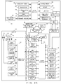
- FIG. 2A is a block diagram mainly illustrating the electrical configuration of an imaging system
- FIG. 2B is a block diagram illustrating the functional configuration of a system controller
- FIG. 3 illustrates an example of the arrangement of terminals on a hot shoe
- FIG. 4 illustrates an example of the hardware configuration of a system controller
- FIG. 5 is a main flowchart illustrating the entirety of processing performed by an imaging system
- FIG. 6 illustrates a subroutine of a hot-shoe-mounting detection process
- FIG. 7 illustrates a subroutine of a line-in-input detection process
- FIG. 8 illustrates a subroutine of a first exemplary IC-recorder mounting process
- FIG. 9 illustrates a subroutine of an IC-recorder-related-set enabling process
- FIG. 10 illustrates examples of menu screens that have undergone a grayout process or the like
- FIG. 11 illustrates a subroutine of a grayout process
- FIG. 12 illustrates a subroutine of an “IC-recorder-related-set” line-connectionless process
- FIG. 13 illustrates a subroutine of a second exemplary IC-recorder mounting process
- FIG. 14 illustrates a table summarizing flags
- FIG. 15 illustrates a subroutine of a live-view display process
- FIG. 16A illustrates a subroutine of an IC-recorder-status display process
- FIG. 16B illustrates a subroutine of an IC-recorder-status display process
- FIG. 17 is a subroutine of an IC-recorder emergency power feeding process
- FIG. 18 illustrates examples of remaining-battery-level display menus
- FIG. 19 illustrates an example of a live-view image displayed on a display
- FIG. 20 illustrates tables illustrating items to be displayed as camera battery information and IC-recorder battery information
- FIG. 21 is a table illustrating details of a link-with-directivity warning icon
- FIG. 22 illustrates exemplary directivity graphs for microphones of an IC recorder
- FIG. 23 depicts a subroutine illustrating a first exemplary slate-tone process
- FIG. 24 is a timing chart illustrating an “On1” process of a first exemplary slate-tone process
- FIG. 25 is a timing chart illustrating an “On2” process of a second exemplary slate-tone process
- FIG. 26 depicts a subroutine illustrating a second exemplary slate-tone process
- FIG. 27 is a timing chart illustrating an “On2” process of a second exemplary slate-tone process
- FIG. 28 illustrates a subroutine of a moving-image shooting process
- FIG. 29 illustrates examples of sound-recording-level adjustment menus
- FIG. 30 illustrates examples of setting menus for a microphone-input limiter
- FIG. 31A illustrates exemplary menus for setting conditions while an IC recorder has been connected
- FIG. 31B illustrates exemplary menus for setting conditions while an IC recorder has been connected.
- a microphone installed in a digital camera and an IC recorder have large differences in sound-recording characteristic and sound-recording condition therebetween, and hence in order to collect sounds with the IC recorder, items of a sound-recording menu of the camera need to be set to optimum values in accordance with IC-recorder specifications.
- various items need to be set for sound-recording conditions, and a long time will be required to make the setting, thereby offering a hindrance to the use of the IC recorder.
- FIG. 1 illustrates the configuration of an imaging system 1 in accordance with embodiments.
- the imaging system 1 includes a camera 10 and an IC recorder 300 .
- the camera 10 is indicated as a digital single-lens-reflex camera that includes a camera body 100 and a lens part 200 .
- the camera 10 may be a lens-fixed camera.
- the IC recorder 300 is a sound recording apparatus that stores sound data in a memory.
- the IC recorder 300 is mounted on a hot shoe 130 provided at an upper portion of the camera body 100 , wherein an external flash can be attached to the hot shoe 130 .
- a line-in input 125 for inputting sounds that are provided on a right side-surface of the camera body 100 is connected to the IC recorder 300 by a cable, and sounds collected by the IC recorder 300 are input to the camera body 100 .
- a release button 119 a and an image-shooting-mode dial 119 b are disposed together as an operation part 119 on a top surface of the camera body 100 .
- a display 120 (not illustrated) is disposed on a back surface of the camera body 100 .
- sounds collected by the IC recorder 300 are recorded by the IC recorder 300 , and simultaneously these sounds are recorded as moving-image sounds by the camera 10 .
- the camera 10 may be referred to as an imaging apparatus.
- the IC recorder 300 may be referred to as a sound recording apparatus.
- FIG. 2A is a block diagram mainly illustrating the electrical configuration of the imaging system 1 .
- the lens part 200 includes an image-shooting lens 201 , a diaphragm mechanism 202 , a liquid crystal diaphragm 203 , and a shake correction lens 204 .
- the image-shooting lens 201 is an optical system for forming an image of a subject.
- the image-shooting lens 201 may include a zoom optical system and a focus adjustment system.
- the diaphragm mechanism 202 and the liquid crystal diaphragm 203 adjust the amount of a pencil of incident light from a subject.
- the shake correction lens 204 is moved in a direction perpendicular to an optical axis so as to cancel out shakes of the camera 10 .
- the lens part 200 includes a shake-correction controller 205 , a liquid-crystal-diaphragm controller 206 , a diaphragm controller 207 , a lens controller 208 , a shake detector 209 , an operation part 210 , and a communication controller 211 .
- the shake-correction controller 205 controls the movement of the shake correction lens 204 in a direction perpendicular to the optical axis.
- the liquid-crystal-diaphragm controller 206 which serves to change a permeability, controls the aperture size of the liquid crystal diaphragm 203 in accordance with an instruction from the camera body 100 so as to adjust the amount of a pencil of incident light from a subject.
- the diaphragm controller 207 controls the aperture size of the diaphragm mechanism 202 in accordance with an instruction from the camera body 100 so as to adjust the amount of a pencil of incident light from the subject.
- the liquid crystal diaphragm 203 which produces no sounds, adjusts the light volume while a moving image is being shot.
- the lens controller 208 moves a predetermined lens included in the image-shooting lens 201 in accordance with an instruction for zooming or a focus adjustment from the camera body 100 .
- the shake detector 209 detects the amount of shakes affecting the lens part 200 .
- the operation part 210 is, for example, a button provided at the lens part 200 so as to manually adjust a focus.
- the communication controller 211 controls a communication between the lens part 200 and the camera body 100 .
- the camera body 100 includes a system controller 101 .
- the system controller 101 performs centralized control of the camera 10 and the camera body 100 .
- the system controller 101 includes, for example, a processor such as a central processing unit (CPU) and an application specific integrated circuit (ASIC).
- a processor such as a CPU may read and run a predetermined control program stored in a nonvolatile memory 122 (this will be described hereinafter) so as to be operated as the system controller 101 and execute various sequences.
- the camera body 100 includes an imaging part 105 , an AD converter 106 , an image processor 107 , and a memory 108 .
- the imaging part 105 includes a shutter 105 a , an image sensor 105 b , and a shake correction mechanism 105 c (none of these are illustrated).
- the shutter 105 a and the image sensor 105 b are located on an optical axis of the image-shooting lens 201 .
- the shutter 105 a which is opened or closed for a pencil of light of an image of a subject that is formed by the image-shooting lens 201 , includes, for example, a publicly known lens shutter or a focal plane shutter.
- the image sensor 105 b which is a two-dimensional solid-state imaging sensor such as a CMOS image sensor or a CCD image sensor, includes: color filters disposed on a front surface of the image sensor 105 b in a Bayer arrangement; and photoelectric conversion elements such as photodiodes arranged in association with the color filters.
- An imaging region is formed by a pixel group that includes color filters and photoelectric conversion elements associated therewith.
- the image sensor 105 b receives, by means of the individual pixels, light collected by the image-shooting lens 201 , converts the received light into a photocurrent, accumulates this photocurrent in a capacitor, and outputs this photocurrent to the AD converter 106 as an analog voltage signal (image signal).
- the shake correction mechanism 105 c holds the image sensor 105 b and is moved in a direction such that shakes of the camera body 100 are canceled.
- the AD converter 106 converts an image signal photoelectrically converted by the image sensor 105 b from analog to digital and outputs the resultant signal to the memory 108 as image data.
- the memory 108 temporarily stores various data such as image data provided by the AD converter 106 and image data processed by the image processor 107 .
- the image processor 107 reads image data temporarily stored in the memory 108 and performs various types of image processing such as white-balance correction processing, synchronization processing, and color-conversion processing for the image data.
- the image processor 107 compresses image data to be recorded in an external memory 121 (this will be described hereinafter) and decompresses image data read from the external memory 121 .
- the camera body 100 also includes an imaging-drive controller 109 , a lens communication unit 110 , a shake detector 111 , an exposure controller 112 , an AF controller 113 , a PC communication unit 114 , and a radio communication unit 115 .
- the imaging-drive controller 109 performs various types of operation control and drive control of the imaging part 105 .
- the lens communication unit 110 communicates with the communication controller 211 of the lens part 200 and controls a data communication between the camera body 100 and the lens part 200 .
- the shake detector 111 detects the amount of shakes of the camera body 100 .
- the exposure controller 112 calculates the luminance of a subject using image data temporarily stored in the memory 108 .
- the luminance of a subject may be calculated using a dedicated photometric sensor.
- the AF (auto focus) controller 113 extracts a high frequency component from image data temporarily stored in the memory 108 and detects a focusing position from a contrast value.
- the PC communication unit 114 controls a communication between the camera body 100 and a personal computer (PC) connected thereto.
- the PC communication unit 114 is, for example, a USB interface.
- a radio communication unit 115 controls a radio communication (e.g., wireless LAN or Bluetooth®) with an external device.
- the camera body 100 also includes a headphone output 116 , a power supply 117 , a power-supply controller 118 , an operation part 119 , a display 120 , an external memory 121 , a nonvolatile memory 122 , a speaker 123 , an internal microphone 124 , a line-in input 125 , a hot shoe 130 , and an external-device controller 131 .
- the headphone output 116 outputs a sound signal to a headphone.
- the power supply 117 supplies power necessary for operations of components of the camera body 100 .
- the power supply 117 includes, for example, a power supply battery such as a rechargeable battery.
- the power-supply controller 118 adjusts a voltage of the power supply 117 to a predetermined voltage so as to supply power to components.
- the power-supply controller 118 detects a power-supply voltage and remaining battery level of a battery that constitutes the power supply 117 .
- the operation part 119 is an input means for inputting an instruction from a user.
- the operation part 119 includes operation members such as the above-described release button 119 a and image-shooting-mode dial 119 b , a moving-image button 119 c , a D-pad 119 d , an OK button 119 e , a slate-tone-function button 119 f , and various input keys.
- the moving-image button 119 c , the D-pad 119 d , the OK button 119 e , and the slate-tone-function button 119 f are disposed on a back surface of the camera body 100 .
- the release button 119 a includes a two-stage switch provided with a first release switch and a second release switch. Pressing the release button 119 a halfway turns on the first release switch, and completely pressing the release button 119 a turns on the second release switch. Turning on the first release switch causes the system controller 101 to perform an image-shooting preparation sequence such as AE processing or AF processing. Turning on the second release switch causes the system controller 101 to perform a still-image-shooting sequence and thus shoot an image.
- the moving-image button 119 c gives an instruction to shoot a moving image.
- the D-pad 119 d selects an item or a condition on, for example, a menu screen displayed by the display 120 , and the OK button 119 e sets the selected condition.
- the D-pad 119 d includes four buttons: an up button, a down button, a right button, and a left button.
- the display 120 performs live-view displaying or playback displaying of a shot image recorded in the external memory 121 and further displays a menu screen for displaying, for example, an exposure control value or for setting, for example, an image-shooting mode.
- the display 120 is, for example, a display apparatus that includes a display such as a liquid crystal monitor or a an organic EL display.
- the external memory 121 is, for example, a record medium that can be attached to and detached from the camera body 100 .
- the external memory 121 stores image data compressed by the image processor 107 , sound data, and data associated with the sound data. Sound data is stored after being synchronized with a shot image as moving-image sounds.
- the storage medium for storing image data, sound data, and the like is not limited to the external memory 121 and may be a storage medium such as a hard disk installed in the camera body 100 .
- the nonvolatile memory 122 is an electrically overwritable nonvolatile memory.
- the nonvolatile memory 122 stores various parameters necessary for operations of the camera 10 and control programs to be run by the system controller 101 .
- the nonvolatile memory 122 stores data on flags such as hot-shoe-connection flags (these flags will be described hereinafter).
- the nonvolatile memory 122 also stores sound-recording conditions (e.g., sound-recording adjustment, microphone limiter) for the IC recorder 300 .
- Sound-recording conditions e.g., sound-recording adjustment, microphone limiter
- a plurality of sound-recording conditions for the IC recorder 300 may be stored collectively as a sound-recording-apparatus setting set.
- the speaker 123 outputs a warning sound or sounds recorded for a moving image.
- the internal microphone 124 is installed in the camera body 100 so as to collect sounds.
- the line-in input 125 serves to input a sound signal output from the IC recorder 300 or an external microphone.
- the line-in input 125 is provided with a line-in switch for detecting the connection (insertion) of, for example, an external microphone.
- the camera body 100 includes a flash light emitter 126 , a flash charger 127 , and a built-in-flash controller 128 .
- the flash light emitter 126 includes, for example, a reflective umbrella and a luminous tube such as a xenon (Xe) tube.
- the flash light emitter 126 receives a light-emission instruction from the built-in-flash controller 128 and emits light using energy accumulated in a capacitor of the flash charger 127 .
- the flash charger 127 accumulates energy required for the flash light emitter 126 to emit light.
- the flash charger 127 includes a booster circuit that boosts a voltage and a capacitor that accumulates energy of the boosted voltage.
- the built-in-flash controller 128 controls a charging operation performed by the flash charger 127 and a light-emitting operation performed by the flash light emitter 126 .
- the camera body 100 includes the hot shoe 130 and the external-device controller 131 .
- the hot shoe 130 is a mount to which an external flash or an external device such as the IC recorder 300 is to be attached.
- the external-device controller 131 communicates with an external device mounted on the hot shoe 130 so as to control this external device.
- the external-device controller 131 may control an external flash mounted on the hot shoe 130 .
- the external-device controller 131 may control the IC recorder 300 mounted on the hot shoe 130 .
- FIG. 3 illustrates an example of the arrangement of terminals on the hot shoe 130 .
- the hot shoe 130 includes an X terminal 130 a , a TXD terminal 130 b , a RXD terminal 130 c , a PWS terminal 130 d , and an STR terminal 130 e.
- the X terminal 130 a is a light-emission trigger terminal that outputs a light-emission trigger to a flash connected to this terminal.
- the TXD terminal 130 b is a data transmission terminal that transmits data from the camera body 100 to an external device (external flash or IC recorder 300 ) connected to this terminal.
- the RXD terminal 130 c is a data reception terminal that allows the camera body 100 to receive data from an external device connected to this terminal.
- the PWS terminal 130 d is a power supply terminal that supplies power to an external device connected to this terminal.
- the STR terminal 130 e is a flash-connection detection terminal that detects the connection of an external flash.
- the system controller 101 is connected to, for example, the image processor 107 to the line-in input 125 , the built-in-flash controller 128 , and the external-device controller 131 .
- the system controller 101 performs various sequences that depend on the user operation.
- FIG. 2B is a block diagram illustrating the functional configuration of the system controller 101 .
- the system controller 101 includes a sound-recording controller 101 a , an external-device detector 101 b , a setting controller 101 c , a displaying-of-remaining-battery-level controller 101 d , and a slate-tone controller 101 e.
- the sound-recording controller 101 a controls sound recording while a moving image is being shot and records sound data in the external memory 121 as moving-image sounds.
- the sound-recording controller 101 a records, in the external memory 121 as sound data, a sound signal from the internal microphone 124 or a sound signal from an external microphone or the IC recorder 300 input via the line-in input 125 .
- the sound-recording controller 101 a processes sounds under, for example, a sound-recording condition set by the setting controller 101 c , digitalizes the sound under predetermined conditions (e.g., sampling frequency, compressibility), and records the digitalized sound in the external memory 121 .
- predetermined conditions e.g., sampling frequency, compressibility
- the external-device detector 101 b detects the type of an external device connected to the camera 10 .
- the external-device detector 101 b detects the type of an external device mounted on the hot shoe 130 by communicating with this external device via the terminal of the hot shoe 130 .
- the external-device detector 101 b identifies an external flash or the IC recorder 300 as an external device.
- the external-device detector 101 b may consider, in terms of expected use of the IC recorder, that the IC recorder 300 has been connected to the camera.
- the external-device detector 101 b Details of the external-device detector 101 b will be described hereinafter with reference to an IC-recorder mounting process (1) depicted in FIG. 8 and an IC-recorder mounting process (2) depicted in FIG. 13 .
- the external-device detector 101 b may also be referred to as a sound-recording-apparatus detector.
- the setting controller 101 c sets a predetermined sound-recording condition for the IC recorder 300 .
- the setting controller 101 c reads a sound-recording condition directed to the IC recorder 300 from the nonvolatile memory 122 and sets this condition.
- the setting controller 101 c performs a grayout process of a menu screen for items (parameters) fixed under the sound-recording condition directed to the IC recorder 300 . Owing to the grayout process, the user can easily determine items that cannot be changed under the sound-recording condition directed to the IC recorder 300 .
- the displaying-of-remaining-battery-level controller 101 d displays a remaining battery level based on a display type selected on the menu screen.
- Display types include, for example, a “remaining battery level (%)”, a “maximum duration of moving-image shooting based on remaining battery level”, a “shorter of ‘maximum duration of sound recording calculated from remaining battery level’ and ‘maximum duration of sound recording calculated from remaining battery level and remaining capacity of memory’”.
- the displaying-of-remaining-battery-level controller 101 d will be described hereinafter with reference to FIGS. 16A and 16B .
- the slate-tone controller 101 e controls generation of a slate tone.
- a slate tone refers to a signal to be mixed with (inserted into) a sound so as to provide synchronization in compiling two pieces of sound record data recorded for the same sound source.
- the sound-recording controller 101 a of the camera 10 causes sound signals collected by the IC recorder 300 and input via the line-in input 125 to be digitally recorded in the external memory 121 as moving-image sound data.
- collected sounds are digitally recorded in an external memory 308 of the IC recorder 300 . Recording slate tones for the two pieces of sound data during image shooting allows the moving-image sound data within the external memory 121 to be easily replaced with the sound data from the IC recorder 300 after image shooting is completed.
- FIG. 4 illustrates an example of the hardware configuration of the system controller 101 .
- the system controller 101 includes a central processing unit (CPU) 1000 , a random access memory (RAM) 1002 , a read only memory (ROM) 1004 , and an input-output interface (IF) 1006 .
- the RAM 1002 constitutes the memory 108 .
- the ROM 1004 constitutes the nonvolatile memory 122 .
- the input-output interface (IF) 1006 has, for example, the PC communication unit 114 or the external memory 121 connected thereto.
- the CPU 1000 , the RAM 1002 , the ROM 1004 , and the input-output IF 1006 are connected to each other by a bus line 1008 .
- the system controller 101 is implemented by software processing performed by the CPU 1000 reading a control program from the ROM 1004 .
- the IC recorder 300 includes a system controller 301 , a nonvolatile memory 302 , an operation part 303 , a PC communication unit 304 , a radio communication unit 305 , a multichannel microphone 306 , and a microphone processor 307 .
- the system controller 301 performs centralized control of the IC recorder 300 .
- the system controller 301 may include a processor such as a central processing unit (CPU) and an application-specific integrated circuit (ASIC).
- a processor such as a CPU may perform various sequences by reading and running a predetermined control program stored in the nonvolatile memory 302 so as to be operated as the system controller 301 .
- the system controller 301 digitally records collected sounds in the external memory 308 (this memory will be described hereinafter) in a recording mode that has been set.
- the IC recorder 300 is typically provided with a microphone with a high sound-collecting quality and sound recording functions achieving a much higher performance and sound quality than the camera 10 , e.g., sound processing for reducing noise such as wind noise, a zoom sound-recording function, and a linear PCM sound-recording function enabling high resolution.
- the nonvolatile memory 302 is an electrically over writable nonvolatile memory and stores various parameters necessary for operations of the IC recorder 300 .
- the nonvolatile memory 302 stores a control program to be run by the system controller 301 .
- the operation part 303 is an input means for inputting an instruction from a user.
- the operation part 303 may include a power button, a sound-recording button, and other operation buttons.
- the PC communication unit 304 controls a communication between the IC recorder 300 and a personal computer (PC) connected to the IC recorder 300 .
- the PC communication unit 304 is, for example, a USB interface.
- the radio communication unit 305 controls a radio communication (e.g., wireless LAN or Bluetooth®) between an external device and the IC recorder 300 .
- the multichannel microphone 306 serves to collect sounds and includes a plurality of microphones.
- the microphone processor 307 processes (e.g., amplifies) a sound signal acquired by the multichannel microphone 306 .
- the system controller 301 achieves various directivities by mixing, at a predetermined ratio, microphone signals of the multichannel microphone 306 that have been processed by the microphone processor 307 .
- the IC recorder 300 includes the external memory 308 , a speaker 309 , a line output 310 , a power supply 311 , a power-supply controller 312 , and a communication controller 313 .
- the external memory 308 which is, for example, a storage medium that can be attached to and detached from the IC recorder 300 , has sound data and data associated with the sound data stored therein.
- the storage medium for storing sound data and the like is not limited to an attachable/detachable external memory and may be a storage medium such as a hard disk installed in the IC recorder 300 .
- the speaker 309 replays stored sounds.
- the line output 310 outputs collected analog sound signals to an external apparatus (e.g., camera 10 ) via an output terminal.
- the power supply 311 supplies power necessary for operations of components of the IC recorder 300 and includes, for example, a power supply battery such as a rechargeable battery.
- the power-supply controller 312 controls the power supply 311 and detects a power-supply voltage and remaining battery level of a battery that constitutes the power supply 311 .
- the power-supply controller 312 controls the switching of power supplied from the camera body 100 to the IC recorder 300 that is performed via the hot shoe 130 .
- the communication controller 313 controls a communication with the camera 10 that is performed via the hot shoe 130 .
- FIG. 5 is a main flowchart illustrating the entirety of processing performed by the imaging system 1 .
- the process depicted in FIG. 5 is performed mainly by the system controller 101 of the camera 10 .
- the system controller 101 of the camera 10 First, descriptions will be given of the overview of the entirety of the processing.
- the system controller 101 performs a hot-shoe-mounting detection process (step S 10 ).
- the hot-shoe-mounting detection process is such that the system controller 101 performs a communication with an external device mounted on the hot shoe via the hot shoe (also referred to as a hot-shoe communication) so as to identify the mounted external device from data received therefrom and determines whether the external device is an IC recorder 300 .
- a system controller 230 performs a line-in-input detection process (step S 20 ).
- the line-in-input detection process is such that the system controller 230 determines whether an external microphone or the like has been connected to the line-in input 125 of the camera 10 .
- the system controller 230 performs an IC-recorder mounting process (step S 30 ).
- the IC-recorder mounting process is such that after detecting the mounting of the IC recorder 300 , the system controller 230 makes camera settings for the IC recorder 300 .
- the system controller 230 performs a live-view display process (step S 40 ).
- the live-view display process is such that the system controller 230 performs an IC-recorder-status display process and a slate-tone process.
- the system controller 230 determines whether the moving-image button 119 c has been turned on (step S 42 ). Upon determining that the moving-image button 119 c has been turned on (YES in step S 42 ), the system controller 230 performs a moving-image shooting process (step S 50 ).
- step S 52 Upon determining that the moving-image button 119 c has not been turned on (NO in step S 52 ), the system controller 230 determines whether the first release switch has been turned on (step S 52 ). Upon determining that the first release switch has not been turned on (NO in step S 52 ), the system controller 230 returns to step S 10 .
- step S 52 Upon determining that the first release switch has been turned on (YES in step S 52 ), the system controller 230 determines whether the second release switch has been turned on (step S 54 ). Upon determining that the second release switch has not been turned on (NO in step S 54 ), the system controller 230 returns to step S 10 . Upon determining that the second release switch has been turned on (YES in step S 54 ), the system controller 230 performs a still-image shooting process (step S 56 ).
- the system controller 230 determines whether a power-off operation has been performed (step S 58 ). Upon determining that the power-off operation has not been performed (NO in step S 58 ), the system controller 230 returns to step S 10 . Upon determining that the power-off operation has been performed (YES in step S 58 ), the system controller 230 performs an end process.
- FIG. 6 illustrates a subroutine of the hot-shoe-mounting detection process.
- the external-device detector 101 b performs a communication via the hot shoe 130 under the control of the external-device controller 131 (step S 100 ).
- the external-device detector 101 b determines a mounted device in accordance with a result of the communication (step S 102 ).
- the mounting of the IC recorder 300 is detected through a communication between the IC recorder 300 and the camera 10 .
- Possible methods for the communication include:
- FIG. 7 illustrates a subroutine of the line-in-input detection process.
- the system controller 230 determines whether a line-in switch of the line-in input 125 has been turned on (step S 200 ).
- the line-in switch is turned on when a cable of an external microphone or IC recorder 300 has been mounted on a terminal of the line-in input 125 .
- the IC-recorder mounting process is a process of making camera settings for an IC recorder 300 after the mounting of the IC recorder 300 has been detected.
- FIG. 8 illustrates a subroutine of a first exemplary IC-recorder mounting process.
- the system controller 101 determines a line-in-state change flag (step S 300 ).
- step S 306 the system controller 101 checks the line-in-state flag.
- the system controller 230 communicates with the IC recorder 300 mounted on the hot shoe 130 via the external-device controller 131 .
- the system controller 230 makes a request for the IC recorder 300 to output a predetermined “pin” signal from the line output 310 .
- a “pin” signal is an authentication signal for allowing the system controller 230 to set an IC-recorder related set in response to the camera 10 detecting that the line output 310 of the IC recorder 300 has been connected to the line-in input 125 of the camera 10 .
- An authentication signal has a certain frequency, amplitude, and waveform for allowing authentication.
- FIG. 2A indicates for convenience sake that the line output 310 and the line-in input 125 are connected. However, the line output 310 is supposed to be connected to the line-in input 125 by the user as suggested in FIG. 1 , and hence the IC recorder 300 is not always connected to the camera 10 .
- the authentication signal is not limited to a signal for setting an IC-recorder related set corresponding to an authenticated IC recorder 300 .
- a calibration function for making optimum settings for the signal may be provided to generate an IC-recorder related set.
- the system controller 101 determines, by means of the external-device detector 101 b , whether a “pin” signal has been received by the line-in input 125 (step S 310 ).
- the system controller 230 performs an IC-recorder-related-set enabling process (step S 314 ).
- the “IC-recorder-related-set enabling process” is a process of enabling an “IC-recorder related set”, i.e., a camera set assumed to use the IC recorder 300 . Enabling or disabling can be manually set using a menu, and hence an IC recorder 300 that is not adapted to the “pin”-signal-based automatic detection system can also be addressed.
- FIG. 9 illustrates a subroutine of the IC-recorder-related-set enabling process.
- the setting controller 101 c sets, for the IC recorder 300 , the sound-recording conditions described in the following. This is because these conditions are appropriately set on the IC-recorder- 300 side.
- the setting controller 101 c may make the settings described in the following by reading a sound-recording-apparatus setting set from the nonvolatile memory 122 .
- the setting controller 101 c fixes sound-recording-level adjustment (external microphone) to “ ⁇ 0” (step S 400 ).
- the setting controller 101 c fixes microphone-input limiter to “Off” (step S 402 ).
- the setting controller 101 c fixes wind-noise reduction to “Off” (step S 404 ). Accordingly, a sound-recording level, a sound-recording limiting function for preventing cracking of recorded sounds, and wind-noise reduction function are addressed entirely on the IC-recorder- 300 side.
- the setting controller 101 c recognizes that the IC recorder 300 has been connected to the line-in input 125 and thus determines that power does not need to be supplied to an external microphone, thereby fixing microphone plug-in power to “Off” (step S 406 ). Settings cannot be changed for fixed menus.
- the setting controller 101 c sets slate tone to “On1” (step S 408 ).
- the setting controller 101 c sets REC synchronization to “On” (step S 410 ).
- the setting controller 101 c performs a grayout process for fixed menus (step S 412 ).
- Settings can be changed for slate tone and REC synchronization.
- the processes of steps S 400 -S 410 may be performed in any order. As described above, settings that can be useful to any user or any image-shooting scene are grayed out to prevent the user from accidentally making a change to the settings. Other settings may be defined as recommended settings to which the user can make a change, as appropriate.
- FIG. 10 illustrates examples of menu screens that have undergone a grayout process or the like.
- a menu ME 1 depicted in FIG. 10 is a movie menu selected on a main menu screen. When the movie sound recording on the lowest line has been selected on menu ME 1 , clicking a right button of the D-pad 119 d will switch the menu to menu ME 2 .
- Menu ME 2 is such that selecting “On” triggers a setting for providing a movie file with sounds and selecting “Off” triggers a setting for providing a movie file with no sounds. Clicking the right button while “On” is selected on menu ME 2 switches the screen to one for setting details of “movie-sound-recording setting”.
- Menu ME 3 is a movie-sound-recording setting screen in an ordinary situation (e.g., while the built-in microphone is used).
- Menu ME 4 which is a sound-recording setting screen provided when the IC recorder 300 is connected to the camera, is a screen that has undergone the above-described grayout process. As indicated in menu ME 4 , a “sound-recording-level adjustment” menu t 1 , a “microphone-input limiter” menu t 2 , a “wind-noise reduction” menu t 3 , and a “microphone plug-in power” menu t 4 are grayed out.
- Menu ME 5 is such that the setting controller 101 c sets a “slate tone” menu t 11 and a “REC synchronization” menu t 12 to On1 and On, respectively. Settings can be changed for “slate tone” and “REC synchronization”, and hence neither the “slate tone” menu t 11 nor the “REC synchronization” menu t 12 undergoes the grayout process.
- a “link-with-microphone-directivity” menu t 13 of menu ME 5 allows a setting to be made as to whether to link the field of view of the camera 10 with the microphone directivity.
- the link with microphone directivity will be described hereinafter by referring to, for example, FIG. 19 .
- An “IC-recorder power feeding” menu t 14 allows a setting to be made as to whether to feed power from the camera 10 to the IC recorder 300 .
- the IC-recorder power feeding will be described hereinafter by referring to FIG. 17 .
- FIG. 11 illustrates a subroutine of the grayout process.
- the setting controller 101 c grays out the “sound-recording-level adjustment” menu t 1 (step S 450 ).
- the setting controller 101 c grays out the “microphone-input limiter” menu t 2 (step S 452 ).
- the setting controller 101 c grays out the “wind-noise reduction” menu t 3 (step S 454 ).
- the setting controller 101 c grays out the “microphone plug-in power” menu t 4 (step S 456 ).
- the processes of steps S 450 -S 456 may be performed in any order.
- step S 316 the system controller 230 performs an “IC-recorder-related-set” line-connectionless process.
- FIG. 12 illustrates a subroutine of the “IC-recorder-related-set” line-connectionless process.
- the system controller 230 sets slate tone to “On2” (step S 460 ). Descriptions will be given of the slate tone “On2” hereinafter by referring to FIG. 25 .
- the first exemplary IC-recorder mounting process is such that when the IC recorder 300 has been mounted on the hot shoe 130 , it is checked using a pin signal whether the IC recorder 300 has also been connected to the line-in input 125 .
- the second exemplary IC-recorder mounting process is such that when the IC recorder 300 has been mounted on the hot shoe 130 , a process that is a simplified version of the first exemplary IC-recorder mounting process is performed on the assumption that the IC recorder 300 has been connected to the line-in input 125 .
- FIG. 13 illustrates a subroutine of the second exemplary IC-recorder mounting process.
- a table depicted in FIG. 14 indicates the flags described above by referring to FIGS. 6-8
- FIG. 5 should be referred to again.
- the system controller 101 performs a live-view display process (step S 40 ).
- FIG. 15 illustrates a subroutine of the live-view display process.
- the system controller 101 performs an IC-recorder-status display process (step S 500 ).
- FIGS. 16A and 16B illustrate subroutines of the IC-recorder-status display process.
- the system controller 101 transmits data to the IC recorder 300 via the TXD terminal 130 b of the hot shoe 130 and receives data from the IC recorder 300 via the RXD terminal 130 c of the hot shoe 130 .
- the system controller 101 also feeds power to the IC recorder 300 via the PWS terminal 130 d on an as-needed basis.
- the external-device detector 101 b performs a hot-shoe communication via the external-device controller 131 (step S 600 ).
- the system controller 101 determines by means of the external-device detector 101 b whether the IC recorder 300 has been detected as an external device (step S 602 ). Upon determining that the IC recorder 300 has not been detected as an external device (NO in step S 602 ), the system controller 101 ends the IC-recorder-status display process.
- the system controller 101 Upon determining that the IC recorder 300 has been detected as an external device (YES in step S 602 ), the system controller 101 obtains a remaining battery level (%) of the IC recorder 300 from the IC recorder 300 (step S 604 ).
- the remaining battery level (%) transmitted from the IC recorder 300 is information displayed on a display (not illustrated) of the IC recorder 300 .
- the system controller 101 performs an IC-recorder emergency power feeding process (step S 606 ).
- FIG. 17 is a subroutine of the IC-recorder emergency power feeding process.
- the system controller 101 determines whether an IC-recorder power feeding menu has been set (step S 670 ). Power is enabled to be fed to, or is disabled from being fed to, the IC recorder by using the “IC-recorder power feeding” menu t 14 of the above-described menu ME 5 depicted in FIG. 10 .
- the system controller 101 determines in accordance with the obtained remaining battery level (%) whether the remaining battery level of the IC recorder 300 corresponds to a limit value (step S 672 ).
- the limit value is, for example, a remaining battery level of 10% or lower.
- the system controller 101 feeds power via the PWS terminal 130 d of the hot shoe 130 (step S 674 ). In particular, the power-supply controller 118 feeds power to the IC recorder 300 .
- step S 670 Upon determining that the IC-recorder power feeding menu has not been set (Off) (NO in step S 670 ), the system controller 101 does not feed power to the IC recorder 300 via the PWS terminal 130 d (step S 676 ). Similarly, upon determining that the remaining battery level of the IC recorder 300 is not the limit value (NO in step S 672 ), the system controller 101 does not feed power to the IC recorder 300 via the PWS terminal 130 d (step S 676 ).
- the system controller 101 determines whether power is being fed from the camera 10 to the IC recorder 300 (step S 608 ). When power is not being fed from the camera 10 to the IC recorder 300 (NO in step S 608 ), the system controller 101 instructs the IC recorder 300 to transmit a maximum duration of sound recording calculated from the remaining battery level (which may hereinafter be referred to as a first maximum duration of sound recording) to the camera. The system controller 101 obtains the maximum duration of sound recording calculated from the remaining battery level from the IC recorder 300 (step S 610 ).
- the system controller 101 instructs the IC recorder 300 to transmit, to the camera 10 , the shorter of the maximum duration of sound recording calculated from the remaining battery level and a maximum duration of sound recording calculated from a remaining capacity of the memory (external memory 308 ) (this shorter maximum duration may hereinafter be referred to as a second maximum duration of sound recording).
- the system controller 101 obtains the shorter maximum duration of sound recording (second maximum duration of sound recording) from the IC recorder 300 (step S 612 ).
- the displaying-of-remaining-battery-level controller 101 d displays the IC-recorder remaining battery level in accordance with the setting of an IC-recorder remaining-battery-level display menu (step S 614 ).
- the displaying-of-remaining-battery-level controller 101 d displays the remaining battery level (%) obtained from the IC recorder 300 (step S 616 ), the maximum duration of sound recording calculated from the remaining battery level obtained from the IC recorder 300 (step S 618 ), or the maximum duration of sound recording obtained from the IC recorder 300 (the shorter of the maximum duration of sound recording calculated from the remaining battery level and the maximum duration of sound recording calculated from the remaining capacity of the memory) (step S 620 ).
- the system controller 101 Upon determining that power is being fed from the camera 10 to the IC recorder 300 (YES in step S 608 ), the system controller 101 instructs the IC recorder 300 to transmit “NONE” to the camera as a maximum duration of sound recording. The system controller 101 obtains “NONE” from the IC recorder 300 (step S 622 ).
- system controller 101 instructs the IC recorder 300 to transmit a maximum duration of sound recording calculated from the remaining capacity of the memory (external memory 308 ) to the camera.
- the system controller 101 obtains, from the IC recorder 300 , the maximum duration of sound recording calculated from the remaining capacity of the memory (step S 624 ). Then, the flow shifts to the processes depicted in FIG. 16B .
- the displaying-of-remaining-battery-level controller 101 d performs the displaying process described in the following in accordance with the setting of the IC-recorder remaining-battery-level display menu (step S 630 ).
- the power consumption of the camera 10 is much larger than that of the IC recorder 300 , and hence the power consumption (%) of the camera 10 and the IC recorder 300 while power is being fed to the IC recorder 300 can be deemed as the power consumption (%) of the camera 10 alone.
- the maximum duration of moving-image shooting calculated from the remaining battery level of the camera 10 and the IC recorder 300 can be deemed as a maximum duration of moving-image shooting calculated from the remaining battery level of the camera 10 alone.
- the displaying-of-remaining-battery-level controller 101 d displays the remaining battery level (%) of the camera 10 (step S 632 ), the maximum duration of moving-image shooting of the camera 10 (calculated from the remaining battery level) (step S 634 ), or the shorter of the maximum duration of sound recording calculated from the remaining memory capacity of the IC recorder 300 and the maximum duration of moving-image shooting calculated from the remaining battery level of the camera 10 (step S 636 ).
- FIG. 18 illustrates examples of the remaining-battery-level display menus.
- FIG. 18 indicates examples of the remaining-battery-level display menus provided when power is not fed from the camera 10 to the IC recorder 300 .
- the remaining-battery-level display menus provided when power is fed from the camera 10 to the IC recorder 300 are essentially the same as the menus depicted in FIG. 18 and thus are not illustrated in the figures.
- Menu ME 10 is the same as the menu ME 1 depicted in FIG. 10 .
- Clicking the right button with a moving-image display setting selected within menu ME 10 shifts the screen to menu ME 11 .
- Clicking the right button with camera remaining-battery-level displaying selected within menu ME 11 shifts the screen to one for making settings to display a remaining battery level (%) (menu ME 12 ).
- Clicking the OK button 119 e with menu ME 12 displayed causes the remaining battery level to be displayed in percentage. Note that this example is based on the assumption that a power battery holder has been mounted on the camera 10 .
- Clicking the down button while menu ME 12 is displayed shifts the screen to one for making settings to display a maximum duration of moving-image shooting calculated from a remaining battery level (menu ME 13 ).
- the maximum duration of moving-image shooting is calculated from the total remaining battery level of the camera and the power battery holder.
- menu ME 16 is such that the displaying of the first maximum duration of sound recording described above with reference to step S 618 is set as the displaying of the remaining battery level of the IC recorder.
- menu ME 17 is such that the displaying of the second maximum duration of sound recording described above with reference to step S 620 is set as the displaying of the remaining battery level of the IC recorder.
- the system controller 101 determines whether a link-with-microphone-directivity menu has been set (step S 640 ).
- the link-with-microphone-directivity menu is a menu for making settings as to whether to link the directivity of the IC recorder 300 with the field of view of the camera 10 . Details of the link-with-microphone-directivity menu will be described hereinafter by referring to FIG. 31B .
- step S 640 Upon determining that the link-with-microphone-directivity menu has not been set (NO in step S 640 ), the system controller 101 does not display a link warning icon on the screen of the display 120 (step S 646 ) and shifts to step S 648 .
- the system controller 101 Upon determining that the link-with-microphone-directivity menu has been set (YES in step S 640 ), the system controller 101 transmits the field of view of the camera 10 from the hot shoe 130 to the IC recorder 300 (step S 642 ). Meanwhile, the system controller 101 displays the link warning icon on the screen of the display 120 (step S 644 ). The link warning icon will be described hereinafter by referring to FIG. 19 .
- the system controller 301 of the IC recorder 300 sets a microphone directivity that depends on the field of view.
- the system controller 301 of the IC recorder 300 transmits microphone directivity data to the camera 10 via the hot shoe 130 .
- the system controller 101 acquires the microphone directivity data from the IC recorder 300 (step S 648 ).
- the system controller 101 displays directivity dB data on the screen of the display 120 (step S 650 ).
- FIG. 19 illustrates an example of a live-view image Dl displayed on the display 120 .
- the live-view image indicates at least one of a remaining battery level, a maximum duration of sound recording, and microphone directivity information as status information of the IC recorder 300 .
- Camera-battery information d 1 and IC-recorder battery information d 2 are indicated on an upper-left portion of live-view image Dl.
- the camera battery information d 1 depicted in FIG. 19 indicates that the maximum duration of moving-image shooting based on the remaining battery level is 90 minutes under a condition in which a power battery holder is mounted.
- Camera-battery information d 1 and IC-recorder battery information d 2 are displayed under the control of the displaying-of-remaining-battery-level controller 101 d.
- a “maximum duration of moving-image shooting based on remaining battery level” associated with the camera 10 alone or “remaining battery level (%)” is selected on the remaining-battery-level display menu and displayed as camera battery information d 1 .
- the system controller 101 calculates the “maximum duration of moving-image shooting based on remaining battery level” or the “remaining battery level (%)” from the remaining battery level of the power supply 117 (including the power battery holder) detected by the power-supply controller 118 .
- the “remaining battery level (%)”, the “maximum duration of sound recording calculated from the remaining battery level”, or the “shorter of the maximum duration of sound recording calculated from the remaining battery level and the maximum duration of sound recording calculated from the remaining capacity of the memory” is displayed as IC-recorder battery information d 2 .
- the IC-recorder battery information d 2 depicted in FIG. 19 indicates that the maximum duration of moving-image shooting that can be performed with the IC recorder 300 is 1490 hours.
- the “remaining battery level (%)” or “maximum duration of moving-image shooting calculated from the remaining battery level” of the entirety of the imaging system 1 (camera 10 and IC recorder 300 ) is displayed as camera battery information d 1 .
- the system controller 101 calculates the “remaining battery level (%)” and the “maximum duration of moving-image shooting based on the remaining battery level” from the remaining battery level of the power supply 117 (including the power battery holder) detected by the power-supply controller 118 .
- the power supply of the camera 10 is primarily relied on. Accordingly, the “remaining battery level (%)” of the camera 10 , the “maximum duration of moving-image shooting calculated from the remaining battery level” of the camera 10 , or the “shorter of the maximum duration of sound recording calculated based on the remaining memory capacity of the IC recorder 300 and the maximum duration of moving-image shooting based on the remaining battery level of the camera 10 ” is displayed as IC-recorder battery information d 2 .
- camera battery information d 1 is the same as IC-recorder battery information d 2 .
- the system controller 101 calculates a “maximum duration of moving-image shooting based on remaining battery level” and a “remaining battery level (%)” for “camera 10 +IC recorder 300 ” on the basis of the remaining battery level of the power supply 117 (including the power battery holder) detected by the power-supply controller 118 and a power consumption value of the IC recorder 300 that is stored in advance.
- FIG. 20 illustrates tables illustrating examples of items to be displayed as camera battery information d 1 and IC-recorder battery information d 2 .
- Camera-battery information d 1 indicates “PBH” when a power battery holder is attached. “Battery within camera body” corresponds to a situation in which a power battery holder is not attached, and “PBH” is not indicated.
- a mark d 3 in an upper-right portion of FIG. 19 indicates the link-with-directivity warning icon.
- Mark d 4 indicates a direction in which a zoom ring is rotated.
- Mark d 5 indicates the focal length of the zoom lens.
- FIG. 21 is a table illustrating details of the link-with-directivity warning icon. In accordance with whether mark d 3 is displayed, a user can determine whether a setting has been made such that the microphone directivity of the IC recorder 300 is linked with the changing of the field of view of the camera 10 .
- a graph d 6 in FIG. 19 indicates a relationship between the field of view of the camera 10 and the microphone directivity of the IC recorder 300 .
- the center of graph d 6 corresponds to an image shooting position.
- Mark d 7 indicates an image shooting range provided by the field of view of the camera.
- Mark d 8 is a curve indicating the microphone directivity.
- the link-with-directivity warning icon and microphone directivity characteristics may be referred to as microphone directivity information.
- Marks d 11 -d 18 in FIG. 19 indicate relative directional sensitivities of the microphone for individual positions with reference to d 10 at the center of the screen (0 dB).
- d 11 indicates the microphone directional sensitivity for a center-right edge of the screen. This means that the microphone directional sensitivity is decreased at the position of the center-right edge of the screen by 0.3 dB in comparison with the center value (0 dB).
- d 12 indicates the microphone directional sensitivity with the center-right side of the field of view enlarged by two times for an offscreen position. At this position, the microphone directional sensitivity is decreased by 3 dB in comparison with the center value (0 dB).
- d 13 indicates the microphone directional sensitivity for a center-left edge of the screen.
- d 14 indicates the microphone directional sensitivity with the center-left side of the field of view enlarged by two times for an offscreen position.
- d 15 indicates the microphone directional sensitivity for a center-top edge of the screen.
- d 16 indicates the microphone directional sensitivity with the center-top side of the field of view enlarged by two times for an offscreen position.
- d 17 indicates the microphone directional sensitivity for a center-bottom edge of the screen.
- d 18 indicates the microphone directional sensitivity with the center-bottom side of the field of view enlarged by two times for an offscreen position. Accordingly, the user can intuitively determine whether the sound collecting direction and range of the sound collecting microphone are appropriate in view of the image shooting screen.
- FIG. 22 illustrates exemplary directivity graphs for microphones of an IC recorder 300 .
- d 7 indicates an image shooting range provided by the field of view of the camera
- d 8 is a curve indicating the directivity.
- the left graph indicates a curve for an omnidirectional microphone.
- the center graph indicates a curve for a unidirectional microphone.
- the right graph indicates a curve for a bidirectional microphone.
- FIG. 15 should be referred to again.
- the system controller 101 performs a slate-tone process (step S 502 ).
- FIG. depicts a subroutine illustrating a first exemplary slate-tone process.
- the system controller 230 determines whether the slate-tone-function button 119 f has been pressed (step S 700 ). Upon determining that the slate-tone-function button 119 f has not been pressed (NO in step S 700 ), the system controller 101 ends the first exemplary slate-tone process.
- step S 700 When the system controller 230 determines that the slate-tone-function button 119 f has been pressed (YES in step S 700 ), the slate-tone controller 101 e performs a process corresponding to the setting of the “slate tone” menu (step S 702 ) (this process will be described in the following). Specific examples of the “slate tone” menu will be described hereinafter by referring to FIG. 31A .
- the slate-tone controller 101 e When the setting of the “slate tone” menu is Off, the slate-tone controller 101 e ends the slate-tone process.
- the slate-tone controller 101 e transmits state tone command 1 from the TXD terminal 130 b of the hot shoe 130 to the IC recorder 300 (step S 704 ). “On1” indicates a mode in which a slate tone is output on the IC-recorder side.
- FIG. 24 is a timing chart illustrating an “On1” process of a first exemplary slate-tone process.
- slate tone command 1 is transmitted from the TXD terminal 130 b to the IC recorder 300 .
- the communication controller 313 of the IC recorder 300 receives slate tone command 1 .
- the system controller 301 of the IC recorder 300 generates a slate tone (also referred to as beep sound) in synchrony with an end bit of slate tone command 1 .
- the system controller 301 of the IC recorder 300 inserts the slate tone into sound data to be recorded by the IC recorder 300 . At the same time, the system controller 301 inserts the slate tone into a sound signal to be output from the line output 310 to the camera 10 .
- the sound signal with the slate tone inserted thereinto is input to a terminal of the line-in input 125 of the camera 10 .
- the slate tone is inserted into moving-image sound data to be recorded by the sound-recording controller 101 a of the camera 10 .
- high-quality PCM data of sounds recorded by the IC recorder 300 may be synchronized with the slate tone and replaced with the moving-image sound data recorded by the camera 10 , so that high-quality sounds can be provided without time deviation.
- the camera 10 may be configured in a manner such that a beep sound is output from the speaker 123 of the camera when the slate-tone-function button 119 f is pressed.
- An example of this is an “On2” of the first exemplary slate-tone process.
- FIG. 25 is a timing chart illustrating the “On2” process of the first exemplary slate-tone process.
- the camera 10 records, for a moving image, a beep sound produced by this camera via the internal microphone 124 or an external microphone connected to the line-in input 125 .
- the beep sound does not necessarily need to be recorded via the internal microphone 124 or the line-in input 125 and may be directly recorded.
- the “On2” process allows the IC recorder 300 to record a slate tone even when the IC recorder 300 is not connected to the camera 10 .
- FIG. 26 depicts a subroutine illustrating a second exemplary slate-tone process.
- the system controller 101 determines whether the slate-tone-function button 119 f has been pressed (step S 720 ). Upon determining that the slate-tone-function button 119 f has not been pressed (NO in step S 720 ), the system controller 230 ends the second exemplary slate-tone process.
- step S 720 When the system controller 101 determines that the slate-tone-function button 119 f has been pressed (YES in step S 720 ), the slate-tone controller 101 e performs a process corresponding to the setting of the “slate tone” menu (step S 722 ) (this process will be described in the following). When the setting of the “slate tone” menu is Off, the system controller 101 ends the second exemplary slate-tone process.
- step S 724 When the setting of the “slate tone” menu is “On1”, the slate-tone controller 101 e transmits slate tone command 1 from the TXD terminal 130 b of the hot shoe 130 to the IC recorder 300 (step S 724 ).
- the process of step S 724 is the same as the process of step S 704 in FIG. 23 , and descriptions thereof are omitted herein.
- the slate-tone controller 101 e transmits slate tone command 2 from the TXD terminal 130 b of the hot shoe 130 to the IC recorder 300 (step S 726 ).
- FIG. 27 is a timing chart illustrating an “On2” process of the second exemplary slate-tone process.
- Pressing the slate-tone-function button 119 f causes the slate-tone controller 101 e to transmit slate tone command 2 from the TXD terminal 130 b to the IC recorder 300 .
- the system controller 301 of the IC recorder 300 Upon receipt of slate tone command 2 , the system controller 301 of the IC recorder 300 provides a slate-tone (beep-sound) waveform in synchrony with an end bit of slate tone command 2 .
- the system controller 301 inserts the produced slate tone into a sound signal and then records this signal in the external memory 308 .
- the slate-tone controller 101 e of the camera 10 also produces and inserts a slate tone into a sound signal output from the IC recorder 300 (a sound signal into which a slate tone has not been inserted) and then records this signal in the external memory 121 .
- the second exemplary slate-tone process is an example in which the IC recorder 300 issues slate tone command 2 instead of the camera 10 actually producing a sound.
- the On2 process of the first exemplary slate-tone process may be such that a slate tone output from the camera speaker cannot be recorded effectively in an environment such as a concert venue where loud sounds are produced.
- the second exemplary slate-tone process in which an actual sound is not used for a slate tone, can accommodate an environment where loud sounds are produced.
- Slate tone command 2 may be wirelessly transmitted. While slate tone command 1 is supposed to be transmitted by a wired link, slate tone command 2 may be transmitted by a wired link or wirelessly.
- FIG. 15 should be referred to again.
- the system controller 101 performs other live-view display processes (step S 504 ) and returns to the main flow depicted in FIG. 5 .
- the system controller 101 determines whether the moving-image button 119 c has been turned on (step S 42 ). Upon determining that the moving-image button 119 c has not been turned on (NO in step S 42 ), the system controller 101 shifts to step S 52 . Upon determining that the moving-image button has been turned on (YES in step S 42 ), the system controller 101 performs the moving-image shooting process (step S 50 ).
- FIG. 28 illustrates a subroutine of the moving-image shooting process.
- the system controller 101 performs the IC-recorder-status display process (step S 800 ).
- the IC-recorder-status display process has been described above with reference to FIGS. 16A and 16B .
- the system controller 101 performs the slate-tone process (step S 802 ).
- the slate-tone process has been described above with reference to FIGS. 23-27 .
- the system controller 101 performs other moving-image shooting processes (step S 804 ). Then, the process returns to the main flow depicted in FIG. 5 .
- the system controller 101 determines whether the first release switch has been turned on (step S 52 ). Upon determining that the first release switch has not been turned on (NO in step S 52 ), the system controller 101 returns to step S 10 . Upon determining that the first release switch has been turned on (YES in step S 52 ), the system controller 101 determines whether the second release switch has been turned on (step S 54 ). Upon determining that the second release switch has not been turned on (NO in step S 54 ), the system controller 101 returns to step S 10 .
- step S 54 Upon determining that the second release switch has been turned on (YES in step S 54 ), the system controller 101 performs the still-image shooting process (step S 56 ). The system controller 101 determines whether a power-off instruction has been given (step S 58 ). Upon determining that a power-off instruction has not been given (NO in step S 58 ), the system controller 101 returns to step S 10 . Upon determining that a power-off instruction has been given (YES in step S 58 ), the system controller 101 performs an end process.
- FIG. 29 illustrates sound-recording-level adjustment menus.
- Clicking the right button with the “sound-recording-level adjustment” selected in the movie-sound-recording setting menu (menu ME 20 ) switches the menu to the sound-recording-level adjustment menu (menu ME 21 ).
- Clicking the right button with a “built-in microphone” selected in the sound-recording-level adjustment menu switches the menu to a built-in-microphone sound-recording-level adjustment menu (menu ME 22 ).
- d 20 i.e., a set value for the microphone sound-recording level, indicates a sound-recording level that has been set.
- the D-pad 119 d the sound-recording level is adjusted within a range from +10 to ⁇ 10 of a microphone sound-recording level d 21 .
- a level bar d 22 dynamically indicates the sound level of an actual microphone. Leading segments of the displayed bar indicate maximum sound pressure levels. Even when the sound pressure is decreased, the leading segments of the level bar d 22 remain at the same position for a predetermined time period. The level bar d 22 is checked to determine whether the sound is excessively small or whether clipping noise has occurred due to an excessively high volume, and the microphone sound-recording level is set to an appropriate value by operating the D-pad 119 d (up and down buttons).
- FIG. 30 illustrates setting menus for a microphone-input limiter. Clicking the right button with “microphone-input limiter” selected in the movie-sound-recording setting menu (menu ME 30 ) switches the menu to one for setting the microphone-input limiter in ON state (menu ME 31 ). Clicking the OK button 119 e sets the microphone-input limiter in ON state. Clicking the down button with the menu ME 31 displayed switches the menu to one for setting the microphone-input limiter in OFF state (menu ME 32 ).
- FIGS. 31A and 31B illustrate menus for setting conditions while an IC recorder has been connected. Clicking the right button with “IC-recorder connection” selected in a movie-sound-recording setting menu (menu ME 40 ) switches the menu to an IC-recorder connection menu (menu ME 41 ).
- Clicking the down button with the menu ME 44 displayed switches the menu to a menu ME 48 depicted in FIG. 31B .
- Clicking the right button with the “REC synchronization” menu t 12 selected in the “IC-recorder connection menu (menu ME 48 )” switches the menu to a menu ME 47 for setting REC synchronization to OFF state.
- Clicking the down button with the menu ME 47 displayed switches the menu to a menu ME 50 for setting REC synchronization to ON state.
- the imaging system 1 in accordance with the embodiments described herein is such that even an inexperienced user can easily make camera settings for an IC recorder connected to the camera.
- settings related to the IC recorder are simultaneously made, and hence a long time does not need to be spent on making the settings. It will be costly to install recording functions for achieving a high sound quality in a camera. Accordingly, high-quality sounds may be recorded in an IC recorder and replaced with sounds recorded by the camera after image shooting so as to provide high-quality moving-image sounds.
- the embodiments are such that sound-recording conditions pertaining to an IC recorder are fixed and cannot be changed while the IC recorder is connected to the camera, thereby preventing sound-recording conditions from being incorrectly set. Conditions fixed for the IC recorder are displayed to be distinguishable from other conditions, and hence the user does not have a difficulty in operating the camera.
- the embodiments are such that the mounting of an IC recorder on the camera is automatically detected, and hence settings do not need to be manually made for the mounting of the IC recorder.
- Power is supplied from the camera to an IC recorder, thereby preventing the IC recorder from having a power shortage.
- the remaining battery level of the IC recorder is displayed on the camera and thus can be easily monitored.
- An IC recorder is mounted on the hot shoe and thus firmly held.
- system controller 101 of the camera 10 is implemented through software processing performed by a CPU that has read a program, but the system controller 101 may be partly or totally implemented by hardware.
- the embodiments herein can provide an imaging system that allows settings to be easily made for an IC recorder connected thereto.
- the present invention is not limited to the described embodiments and may be achieved in an implementation phase with components modified without departing from the gist of the invention.
- Various inventions may be provided by combining, as appropriate, a plurality of components disclosed with reference to the embodiments. For example, all components indicated with reference to an embodiment may be combined as appropriate. Moreover, components of different embodiments may be combined as appropriate. Various modifications and applications can be provided in this way without departing the gist of the invention.
Landscapes
- Physics & Mathematics (AREA)
- General Physics & Mathematics (AREA)
- Engineering & Computer Science (AREA)
- Multimedia (AREA)
- Signal Processing (AREA)
- Studio Devices (AREA)
- Exposure Control For Cameras (AREA)
- Details Of Cameras Including Film Mechanisms (AREA)
- Accessories Of Cameras (AREA)
Abstract
Description
Claims (5)
Applications Claiming Priority (2)
| Application Number | Priority Date | Filing Date | Title |
|---|---|---|---|
| JP2018-102515 | 2018-05-29 | ||
| JP2018102515A JP7086716B2 (en) | 2018-05-29 | 2018-05-29 | Imaging system |
Publications (2)
| Publication Number | Publication Date |
|---|---|
| US20190369478A1 US20190369478A1 (en) | 2019-12-05 |
| US10691011B2 true US10691011B2 (en) | 2020-06-23 |
Family
ID=68694791
Family Applications (1)
| Application Number | Title | Priority Date | Filing Date |
|---|---|---|---|
| US16/417,582 Expired - Fee Related US10691011B2 (en) | 2018-05-29 | 2019-05-20 | Imaging system |
Country Status (2)
| Country | Link |
|---|---|
| US (1) | US10691011B2 (en) |
| JP (1) | JP7086716B2 (en) |
Families Citing this family (1)
| Publication number | Priority date | Publication date | Assignee | Title |
|---|---|---|---|---|
| JP7676224B2 (en) * | 2021-05-26 | 2025-05-14 | キヤノン株式会社 | Image stabilizer control device, imaging device, lens device |
Citations (8)
| Publication number | Priority date | Publication date | Assignee | Title |
|---|---|---|---|---|
| US20070199076A1 (en) * | 2006-01-17 | 2007-08-23 | Rensin David K | System and method for remote data acquisition and distribution |
| US20100254543A1 (en) * | 2009-02-03 | 2010-10-07 | Squarehead Technology As | Conference microphone system |
| US20110221949A1 (en) * | 2010-03-10 | 2011-09-15 | Olympus Imaging Corp. | Shooting apparatus |
| US20110221910A1 (en) * | 2010-03-09 | 2011-09-15 | Olympus Imaging Corp. | Imaging device, and system for audio and image recording |
| JP5862320B2 (en) | 2012-01-23 | 2016-02-16 | 株式会社Jvcケンウッド | Imaging device adapter and imaging device |
| US20170034575A1 (en) | 2015-07-31 | 2017-02-02 | Teac Corporation | Camera-connection-type sound recording apparatus |
| US20180278841A1 (en) * | 2017-03-27 | 2018-09-27 | Panasonic Intellectual Property Management Co., Ltd. | Imaging apparatus |
| US10270962B1 (en) * | 2017-12-13 | 2019-04-23 | North Of You Llc | Automatic camera settings configuration for image capture |
Family Cites Families (3)
| Publication number | Priority date | Publication date | Assignee | Title |
|---|---|---|---|---|
| JP2006064763A (en) | 2004-08-24 | 2006-03-09 | Sony Corp | Image pickup apparatus and setting change method thereof |
| JP2011223402A (en) | 2010-04-12 | 2011-11-04 | Olympus Imaging Corp | Imaging apparatus and recording apparatus |
| JP2013003392A (en) | 2011-06-17 | 2013-01-07 | Sanyo Electric Co Ltd | Sound recording apparatus |
-
2018
- 2018-05-29 JP JP2018102515A patent/JP7086716B2/en not_active Expired - Fee Related
-
2019
- 2019-05-20 US US16/417,582 patent/US10691011B2/en not_active Expired - Fee Related
Patent Citations (9)
| Publication number | Priority date | Publication date | Assignee | Title |
|---|---|---|---|---|
| US20070199076A1 (en) * | 2006-01-17 | 2007-08-23 | Rensin David K | System and method for remote data acquisition and distribution |
| US20100254543A1 (en) * | 2009-02-03 | 2010-10-07 | Squarehead Technology As | Conference microphone system |
| US20110221910A1 (en) * | 2010-03-09 | 2011-09-15 | Olympus Imaging Corp. | Imaging device, and system for audio and image recording |
| US20110221949A1 (en) * | 2010-03-10 | 2011-09-15 | Olympus Imaging Corp. | Shooting apparatus |
| JP5862320B2 (en) | 2012-01-23 | 2016-02-16 | 株式会社Jvcケンウッド | Imaging device adapter and imaging device |
| US20170034575A1 (en) | 2015-07-31 | 2017-02-02 | Teac Corporation | Camera-connection-type sound recording apparatus |
| JP2017034440A (en) | 2015-07-31 | 2017-02-09 | ティアック株式会社 | Camera connection type sound recording device |
| US20180278841A1 (en) * | 2017-03-27 | 2018-09-27 | Panasonic Intellectual Property Management Co., Ltd. | Imaging apparatus |
| US10270962B1 (en) * | 2017-12-13 | 2019-04-23 | North Of You Llc | Automatic camera settings configuration for image capture |
Also Published As
| Publication number | Publication date |
|---|---|
| JP2019208131A (en) | 2019-12-05 |
| JP7086716B2 (en) | 2022-06-20 |
| US20190369478A1 (en) | 2019-12-05 |
Similar Documents
| Publication | Publication Date | Title |
|---|---|---|
| US8462254B2 (en) | Image pickup apparatus capable of setting a photographic condition and control method therefor | |
| US8643734B2 (en) | Automatic engagement of image stabilization | |
| US8750674B2 (en) | Remotely controllable digital video camera system | |
| JP5456517B2 (en) | Camera body and imaging device | |
| US7986299B2 (en) | Remote control apparatus, remote control system and device-specific information display method | |
| US8712231B2 (en) | Camera body, and camera system | |
| US20130077932A1 (en) | Digital video camera system having two microphones | |
| US20120113515A1 (en) | Imaging system with automatically engaging image stabilization | |
| US20120237050A1 (en) | Sound pickup device | |
| US10691011B2 (en) | Imaging system | |
| JP5868038B2 (en) | Imaging apparatus, control method therefor, program, and storage medium | |
| JP2012019341A (en) | Imaging device, and method and program for controlling the same | |
| US20130063621A1 (en) | Imaging device | |
| JP2010074795A (en) | Image pickup device, its control method, and program | |
| JP5473201B2 (en) | Imaging apparatus and control method thereof | |
| WO2012035675A1 (en) | Audio recording device | |
| US9064487B2 (en) | Imaging device superimposing wideband noise on output sound signal | |
| US20050237420A1 (en) | Camera system and camera main unit | |
| KR101464532B1 (en) | Digital image processing apparatus and method for controlling the same | |
| JP2009089325A (en) | Information device and battery level detection method | |
| JP7103358B2 (en) | Communication control device, control method and program of communication control device | |
| JP2009077305A (en) | Imaging apparatus and imaging control method | |
| US12155962B2 (en) | Image pickup apparatus having function of recording voice data, control method for image pickup apparatus, and storage medium | |
| JP4085320B2 (en) | Digital camera | |
| JP5328121B2 (en) | Imaging device and illumination device |
Legal Events
| Date | Code | Title | Description |
|---|---|---|---|
| AS | Assignment |
Owner name: OLYMPUS CORPORATION, JAPAN Free format text: ASSIGNMENT OF ASSIGNORS INTEREST;ASSIGNORS:KUDO, HIROKI;SAKURAI, KAZUKI;KUNISHIGE, KEIJI;REEL/FRAME:049235/0677 Effective date: 20190516 |
|
| FEPP | Fee payment procedure |
Free format text: ENTITY STATUS SET TO UNDISCOUNTED (ORIGINAL EVENT CODE: BIG.); ENTITY STATUS OF PATENT OWNER: LARGE ENTITY |
|
| STPP | Information on status: patent application and granting procedure in general |
Free format text: DOCKETED NEW CASE - READY FOR EXAMINATION |
|
| STPP | Information on status: patent application and granting procedure in general |
Free format text: NON FINAL ACTION MAILED |
|
| STPP | Information on status: patent application and granting procedure in general |
Free format text: NOTICE OF ALLOWANCE MAILED -- APPLICATION RECEIVED IN OFFICE OF PUBLICATIONS |
|
| STPP | Information on status: patent application and granting procedure in general |
Free format text: PUBLICATIONS -- ISSUE FEE PAYMENT VERIFIED |
|
| STCF | Information on status: patent grant |
Free format text: PATENTED CASE |
|
| FEPP | Fee payment procedure |
Free format text: MAINTENANCE FEE REMINDER MAILED (ORIGINAL EVENT CODE: REM.); ENTITY STATUS OF PATENT OWNER: LARGE ENTITY |
|
| LAPS | Lapse for failure to pay maintenance fees |
Free format text: PATENT EXPIRED FOR FAILURE TO PAY MAINTENANCE FEES (ORIGINAL EVENT CODE: EXP.); ENTITY STATUS OF PATENT OWNER: LARGE ENTITY |
|
| STCH | Information on status: patent discontinuation |
Free format text: PATENT EXPIRED DUE TO NONPAYMENT OF MAINTENANCE FEES UNDER 37 CFR 1.362 |
|
| FP | Lapsed due to failure to pay maintenance fee |
Effective date: 20240623 |