US10690899B2 - Image observation device and microscope system - Google Patents
Image observation device and microscope system Download PDFInfo
- Publication number
- US10690899B2 US10690899B2 US16/285,513 US201916285513A US10690899B2 US 10690899 B2 US10690899 B2 US 10690899B2 US 201916285513 A US201916285513 A US 201916285513A US 10690899 B2 US10690899 B2 US 10690899B2
- Authority
- US
- United States
- Prior art keywords
- image
- focusing
- frame
- omnifocal
- window portions
- Prior art date
- Legal status (The legal status is an assumption and is not a legal conclusion. Google has not performed a legal analysis and makes no representation as to the accuracy of the status listed.)
- Active
Links
Images


Classifications
-
- G—PHYSICS
- G02—OPTICS
- G02B—OPTICAL ELEMENTS, SYSTEMS OR APPARATUS
- G02B21/00—Microscopes
- G02B21/36—Microscopes arranged for photographic purposes or projection purposes or digital imaging or video purposes including associated control and data processing arrangements
- G02B21/365—Control or image processing arrangements for digital or video microscopes
- G02B21/367—Control or image processing arrangements for digital or video microscopes providing an output produced by processing a plurality of individual source images, e.g. image tiling, montage, composite images, depth sectioning, image comparison
-
- G—PHYSICS
- G02—OPTICS
- G02B—OPTICAL ELEMENTS, SYSTEMS OR APPARATUS
- G02B21/00—Microscopes
-
- G—PHYSICS
- G02—OPTICS
- G02B—OPTICAL ELEMENTS, SYSTEMS OR APPARATUS
- G02B21/00—Microscopes
- G02B21/0004—Microscopes specially adapted for specific applications
- G02B21/002—Scanning microscopes
- G02B21/0024—Confocal scanning microscopes (CSOMs) or confocal "macroscopes"; Accessories which are not restricted to use with CSOMs, e.g. sample holders
- G02B21/0052—Optical details of the image generation
- G02B21/006—Optical details of the image generation focusing arrangements; selection of the plane to be imaged
-
- G—PHYSICS
- G02—OPTICS
- G02B—OPTICAL ELEMENTS, SYSTEMS OR APPARATUS
- G02B21/00—Microscopes
- G02B21/24—Base structure
- G02B21/241—Devices for focusing
- G02B21/244—Devices for focusing using image analysis techniques
-
- H—ELECTRICITY
- H04—ELECTRIC COMMUNICATION TECHNIQUE
- H04N—PICTORIAL COMMUNICATION, e.g. TELEVISION
- H04N23/00—Cameras or camera modules comprising electronic image sensors; Control thereof
- H04N23/60—Control of cameras or camera modules
- H04N23/63—Control of cameras or camera modules by using electronic viewfinders
- H04N23/631—Graphical user interfaces [GUI] specially adapted for controlling image capture or setting capture parameters
-
- H—ELECTRICITY
- H04—ELECTRIC COMMUNICATION TECHNIQUE
- H04N—PICTORIAL COMMUNICATION, e.g. TELEVISION
- H04N23/00—Cameras or camera modules comprising electronic image sensors; Control thereof
- H04N23/60—Control of cameras or camera modules
- H04N23/63—Control of cameras or camera modules by using electronic viewfinders
- H04N23/633—Control of cameras or camera modules by using electronic viewfinders for displaying additional information relating to control or operation of the camera
- H04N23/635—Region indicators; Field of view indicators
-
- H—ELECTRICITY
- H04—ELECTRIC COMMUNICATION TECHNIQUE
- H04N—PICTORIAL COMMUNICATION, e.g. TELEVISION
- H04N23/00—Cameras or camera modules comprising electronic image sensors; Control thereof
- H04N23/60—Control of cameras or camera modules
- H04N23/67—Focus control based on electronic image sensor signals
- H04N23/676—Bracketing for image capture at varying focusing conditions
-
- H04N5/232—
-
- H04N5/23212—
-
- H04N5/232133—
-
- H04N5/232933—
-
- H04N5/232945—
Definitions
- the present invention relates to an image observation device and a microscope system.
- an omnifocal image which is focused in substantially the entire region thereof, is generated by using a plurality of images (hereinafter referred to as the Z-stack image) captured while shifting the focal position in the optical-axis direction, and by combining pixels of images having maximum focusing degrees at individual pixel positions (for example, see Patent Literature 1).
- Patent Literature 1 in a case in which the focusing degree at each position has two or more peak values, these peak values are detected as a plurality of candidate values, and a plurality of omnifocal images are generated by utilizing a specific number of Z-stack images for each of the detected candidate values.
- An aspect of the present invention is an image observation device configured to: perform a reference-image generating that generates a reference image on a basis of one or more two-dimensional images of a Z-stack image constituted of the plurality of two-dimensional images that are acquired by shifting a focal position in an optical-axis direction of an objective lens; perform a frame generating that generates, on the generated reference image, a frame that has a plurality of window portions covering different small regions of the reference image and that is superimposed on the reference image; perform a frame operating that allows a user to operate the generated frame so as to be moved with respect to the reference image; perform a focal-range allocating that allocates different focal ranges to the respective window portions of the generated frame; perform an omnifocal-image generating that generates, for the respective small regions covered by the respective window portions, omnifocal images by using, among the two-dimensional images in regions corresponding to the respective small regions, the two-dimensional images in the focal ranges allocated to the respective window portions; perform an image replacing that
- Another aspect of the present invention is a microscope system provided with: a microscope that acquires the Z-stack image; and the abovementioned image observation device.
- FIG. 1 is a block diagram showing an image observation device and a microscope system according to an embodiment of the present invention.
- FIG. 2 is a diagram for explaining a Laplacian pyramid for calculating a focusing degree.
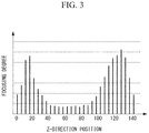
- FIG. 3 is a diagram showing an example of a focusing-degree distribution that is generated by the image observation device in FIG. 1 .
- FIG. 4 is a flowchart for explaining a method of setting a detection range for focusing-degree peaks (hereinafter referred to as “focusing peaks”) by means of the image observation device in FIG. 1 .
- FIG. 5 is a diagram showing focusing peak search ranges, which are generated by dividing a Z-range in the flowchart in FIG. 4 .
- FIG. 6 is a diagram showing focusing peak detection ranges set in the flowchart in FIG. 4 .
- FIG. 7 is a schematic diagram showing an example of Z-ranges that are determined, for each focusing peak, by a Z-range determining unit of the image observation device in FIG. 1 .
- FIG. 8 is a diagram showing an example of a reference image and a frame that are displayed, in a superimposed manner, on a display unit of the image observation device in FIG. 1 .
- FIG. 9 is a flowchart for explaining a method of observing an image by means of the microscope system of the present invention.
- FIG. 10 is a diagram showing an actual display example of the image and the frame that are displayed on the display unit of the image observation device in FIG. 1 .
- FIG. 11 is a diagram showing a state in which the frame is moved in the display example in FIG. 10 .
- FIG. 12 is a diagram showing a modification of the frame in the image observation device in FIG. 1 .
- the microscope system 1 is provided with: a microscope 2 that acquires a Z-stack image constituted of a plurality of two-dimensional images of an imaging object O by shifting the focal position in the optical-axis direction of an objective lens 4 ; and the image observation device 3 for observing the Z-stack image acquired by the microscope 2 .
- the microscope 2 is provided with: a stage 5 on which the imaging object O is placed; the objective lens 4 that collects light coming from the imaging object O placed on the stage 5 ; and an image-acquisition unit 6 that captures an image of the light coming from the imaging object O and collected by the objective lens 4 .
- the microscope 2 may be of an arbitrary type, the microscope 2 has a structure in which the relative positions of the objective lens 4 and the stage 5 can be changed in a direction along the optical axis of the objective lens 4 , and it is possible to move the focal position of the objective lens 4 , in the optical-axis direction thereof, with respect to the imaging object O.
- the microscope 2 acquires a plurality of two-dimensional images while moving the focal position of the objective lens 4 , in the optical-axis direction thereof, by minute distances with respect to the imaging object O, thereby acquiring a Z-stack image constituted of the plurality of acquired two-dimensional images.
- the image observation device 3 is provided with: a focusing-degree calculating unit 7 to which the Z-stack image acquired by the microscope 2 is input and that calculates focusing degrees at each pixel position and generates a focusing-degree distribution; an omnifocal-image generating unit 8 that generates an omnifocal image on the basis of the generated focusing-degree distribution; and a display unit 9 that displays the generated omnifocal image.
- the image observation device 3 is provided with: a target-position setting unit (position setting unit) 10 with which a user who has confirmed a target position on the omnifocal image displayed on the display unit 9 sets the target position on the omnifocal image; a frame generating unit 12 that generates a frame having a plurality of window portions on the basis of information about the set target position and information about focal ranges determined by a Z-range determining unit 11 , which will be described later; a focal-range allocating unit 13 that allocates different focal ranges to the respective window portions of the generated frame; an image replacing unit 14 that replaces images in the window portions with omnifocal images generated, for the respective focal ranges, in the omnifocal-image generating unit (reference-image generating unit) 8 ; and a frame operating unit 15 for allowing the user to move the frame displayed on the display unit 9 .
- a target-position setting unit (position setting unit) 10 with which a user who has confirmed a target position on the omnifocal
- the focusing-degree calculating unit 7 generates a focusing-degree distribution for generating a reference image, which is an omnifocal image for the entire range of two-dimensional images constituting a Z-stack image, and a focusing-degree distribution at the pixel at the target position set by the target-position setting unit 10 .
- the focusing-degree calculating unit 7 utilizes, for example, a Laplacian pyramid capable of representing a high-frequency component, such as edge information, and calculates a focusing degree on the basis of the high-frequency component.
- a digital image can be decomposed into a low-frequency component (Gaussian component) and a high-frequency component (Laplacian component) and can be represented as pyramid levels due to correlations between resolutions.
- the high-frequency component can be represented as a level of a Laplacian pyramid.
- the Laplacian pyramid indicates a Laplacian component that is lost when a low-frequency component is obtained from an original image, and the frequency band differs depending on the level thereof.
- FIG. 2 shows an example of the Laplacian pyramid.
- LPF indicates low-pass filtering
- DS indicates downsampling
- US indicates upsampling.
- a four-level Laplacian pyramid is constructed, and a focusing degree is calculated on the basis of a second-level Laplacian component in which an edge component of the imaging object structure is considered to be stably included.
- FIG. 2 shows three levels among the four levels. Note that the level to be utilized need not be one arbitrary level, and Laplacian components in the individual bands may be blended with optimal weights on the basis of the observation conditions or the characteristics of the imaging object structure.
- the focusing-degree calculating method is not limited to the abovementioned method, and any known method, such as a calculating method based on a wavelet transform coefficient, may be employed.
- the focusing-degree calculating unit 7 arranges the focusing degrees calculated as described above according to Z-direction positions of the respective two-dimensional images, as shown in FIG. 3 , thereby generating a focusing-degree distribution.
- the focusing-degree calculating unit 7 In the generation of a reference image, the focusing-degree calculating unit 7 generates focusing-degree distributions at all pixel positions of the two-dimensional images and sends the focusing-degree distributions to the omnifocal-image generating unit 8 .
- the focusing-degree calculating unit 7 When a target position is set by the target-position setting unit 10 , the focusing-degree calculating unit 7 generates a focusing-degree distribution only at the pixel position at the set target position and sends the focusing-degree distribution to the Z-range determining unit 11 .
- the Z-range determining unit 11 detects focusing peaks having maximum focusing degrees in the focusing-degree distribution at the target position, said distribution having been sent from the focusing-degree calculating unit 7 , and determines focal ranges, for each of the focusing peaks, for generating omnifocal images.
- the detection of focusing peaks is performed in the Z-range determining unit 11 as described below.
- a focusing peak search range Sz is set.
- a constant N is 1
- a search range Sz(N) is the entire Z-range (step S 1 ).
- the initial search range Sz(N) is 0 to 140.
- an analyzing target distribution Az(N) is obtained (step S 2 ). Specifically, each focusing degree in the focusing-degree distribution is compared with a prescribed threshold, and only the focusing degrees greater than the threshold are included in the analyzing target distribution.
- a constant a is set to 1 (step S 3 )
- a variance value ⁇ (a) of the obtained analyzing target distribution Az(a) is calculated (step S 4 ), and it is determined whether or not the variance value ⁇ (a) is less than or equal to a prescribed threshold ⁇ T (step S 5 ).
- the variance value ⁇ is less than or equal to the prescribed threshold ⁇ T
- it can be estimated that the number of focusing peaks is one or zero, and, in other cases, it can be estimated that the number of focusing peaks is two or more.
- step S 6 the constant N is incremented (step S 6 ), the Z-range is divided into Z(N) (step S 7 ), and search ranges Sz(N) are respectively reset to Z(N) (steps S 8 to S 11 ). Then, the processes from step S 2 are repeated for each of the reset search ranges Sz(N).
- a mean value of the analyzing target distribution Az(N) may be set as a dividing position.
- the mean value is 66
- the reset search range Sz( 1 ) and search range Sz( 2 ) are 0 to 65 and 67 to 140, respectively.
- the method of setting a dividing position is not limited to this method, and it is permissible to employ a method in which a peak detection function, such as the Fisher Distance, is created from the analyzing target distribution Az(N), and start points, midpoints, and end points of peaks are obtained on the basis of positive and negative changes in the value of the created peak detection function.
- a peak detection function such as the Fisher Distance
- a search range Sz(a) is set as a detection range Pz(a) (steps S 12 to S 14 ), and the processes from step S 4 are repeated until detection ranges Pz(N) are set for all search ranges Sz(N).
- reference signs a and b indicate the constants.
- FIG. 6 shows a case in which the number of focusing peaks is two in the entire Z-range, and two detection ranges Pz( 1 ) and Pz( 2 ) are determined.
- a Z-position of a focusing peak is detected in each of the detection ranges Pz(N).
- a Z-position having the maximum focusing degree is detected as the focusing peak.
- the Z-range determining unit 11 determines, for each of the detected focusing peaks, Z-ranges, in other words, focal ranges to be utilized for generation of omnifocal images.
- three Z-ranges are determined, for each of the focusing peaks, as the Z-ranges to be utilized for generation of the omnifocal images; namely, the detection range (pattern B or E) of the focusing peak and two Z-ranges (patterns A and C or patterns D and F) on both sides of the focusing peak serving as a boundary.
- the omnifocal-image generating unit 8 When the omnifocal-image generating unit 8 receives, from the focusing-degree calculating unit 7 , focusing-degree distributions at all pixel positions for generating a reference image, the omnifocal-image generating unit 8 selects, in each of the focusing-degree distributions, a pixel value of any two-dimensional image in the Z-direction, the image having the highest focusing degree, and generates an omnifocal image by combining the pixel values selected at all the pixel positions.
- the omnifocal-image generating unit 8 when the omnifocal-image generating unit 8 receives a plurality of Z-ranges from the Z-range determining unit 11 , the omnifocal-image generating unit 8 generates omnifocal images for each focusing peak by using Z-stack images corresponding to the respective Z-ranges that are received.
- the method of generating an omnifocal image is basically the same as the method of generating a reference image, the methods differ in the Z-range and the pixel range of the two-dimensional images, the ranges being used for the image generation.
- the target-position setting unit 10 is, for example, an input device, such as a mouse, for moving a cursor on an image displayed on the display unit 9 and sets a target position when the user moves the mouse and clicks on the target position of high interest.
- an input device such as a mouse
- the frame generating unit 12 when the target-position setting unit 10 sets a target position and the Z-range determining unit 11 determines Z-ranges of Z-stack images that are used to generate omnifocal images for said target position, the frame generating unit 12 generates a frame to be displayed in a superimposed manner on the reference image.
- the generated frame is displayed in a superimposed manner on the reference image on the display unit 9 , with the center thereof located at the target position set by the target-position setting unit 10 .
- the focal-range allocating unit 13 allocates the six Z-ranges determined by the Z-range determining unit 11 to the respective window portions of the frame.
- the frame has, for example, the window portions of two rows and three columns; the two Z-ranges serving as the detection ranges are respectively allocated to the center window portions in the respective rows; the Z-ranges on the deep side of the focusing peaks in the depth direction are respectively allocated to the window portions in the left column; and the Z-ranges on the front side of the focusing peaks in the depth direction are respectively allocated to the window portions in the right column.
- the omnifocal-image generating unit 8 receives the Z-stack images, the positional information of the window portions of the frame, and the information about the Z-ranges allocated to the respective window portions and generates, for respective small regions corresponding to the window portions, omnifocal images by using the Z-ranges allocated to the respective window portions. Then, the image replacing unit 14 replaces the small regions of the reference image, corresponding to the respective window portions, with the generated six omnifocal images, and the replaced images are displayed on the display unit 9 .
- the user can move the position of the frame that is displayed on the display unit 9 by means of the frame operating unit 15 constituted of, for example, an input unit, such as a mouse, and a GUI.
- the frame operating unit 15 constituted of, for example, an input unit, such as a mouse, and a GUI.
- the frame is moved, the small regions corresponding to the respective window portions change, and thus, the omnifocal images are generated by using new positional information of the window portions and Z-ranges allocated to the window portions, thereby being updated.
- the imaging object O is placed on the stage 5 of the microscope 2 , and while the relative positions of the objective lens 4 and the stage 5 along the optical-axis direction of the objective lens 4 are changed by minutely moving the positions, a two-dimensional image of the imaging object O is acquired at each position and stored, whereby a Z-stack image is acquired (step S 100 ).
- the Z-stack image acquired in the microscope 2 is input to the image observation device 3 .
- the focusing-degree calculating unit 7 generates a focusing-degree distribution over the entire range of the two-dimensional images constituting the Z-stack image and for each pixel position of the two-dimensional images, and the generated focusing-degree distributions are sent to the omnifocal-image generating unit 8 .
- the omnifocal-image generating unit 8 extracts, at each of the pixel positions, a pixel value of any two-dimensional image in the Z-direction, the image having the maximum focusing degree, on the basis of the input Z-stack image and the focusing-degree distributions at all the pixel positions, and generates an omnifocal image for the entire range of the two-dimensional images by combining the extracted pixel values, and the omnifocal image is displayed on the display unit 9 as a reference image (step S 101 ).
- the user looks at the reference image displayed on the display unit 9 and sets a target position of high interest (step S 102 ).
- the coordinates of the set target position are sent to the focusing-degree calculating unit 7 , and a focusing-degree distribution at said coordinates is generated (step S 103 ).
- the generated focusing-degree distribution is sent to the Z-range determining unit 11 , and the Z-range determining unit 11 performs processing for setting focusing peak detection ranges, processing for detecting focusing peaks (step S 104 ), and processing for determining Z-ranges for each of the detected focusing peaks (step S 105 ).
- the Z-range determining unit 11 performs processing for setting focusing peak detection ranges, processing for detecting focusing peaks (step S 104 ), and processing for determining Z-ranges for each of the detected focusing peaks (step S 105 ).
- step S 107 information about the generated frame is sent to the focal-range allocating unit 13 , and the Z-ranges determined by the Z-range determining unit 11 are allocated to the respective window portions of the frame one by one.
- the frame generating unit 12 calculates positions of the individual window portions on the reference image on the basis of the target position set by the target-position setting unit 10 so that the generated frame is displayed on the reference image, with the center thereof located at the target position set by the target-position setting unit 10 .
- the omnifocal-image generating unit 8 receives the Z-stack images input from the microscope 2 , the positional information of the window portions of the frame, which has been sent from the focal-range allocating unit 13 , and the information about the Z-ranges allocated to the respective window portions and generates, for respective small regions corresponding to the window portions, omnifocal images from the Z-stack images by using the information about the Z-ranges allocated to the window portions (step S 108 ).
- the image replacing unit 14 employs the omnifocal images generated for the respective window portions as the images in the window portions of the frame, the frame is superimposed on the reference image, and an image in which the omnifocal images having different Z-ranges are employed in the respective window portions of the frame is displayed on the display unit 9 (step S 109 ).
- FIG. 10 shows an actual display example.
- the user can move the frame with respect to the reference image by grabbing the frame that is displayed on the display unit 9 and dragging the frame by operating the frame operating unit 15 provided with a mouse.
- the positions of the individual window portions change; thus, it is determined whether or not the frame has been moved (step S 110 ) and, in a case in which the frame has been moved, the focal-range allocating unit 13 sends new positional information of the window portions to the omnifocal-image generating unit 8 , and the omnifocal images are re-generated and updated (steps S 106 to S 109 ).
- FIG. 11 shows an actual display example in the case in which the frame is moved.
- step S 111 the processing is ended.
- a user can freely move a frame that is displayed in a superimposed manner on a reference image on the display unit 9 and, by simply matching any of the window portions that are defined by the frame with a target position, can perform an observation at the target position by means of omnifocal images for Z-ranges that are allocated to said window portions.
- omnifocal images for Z-ranges that are allocated to said window portions.
- each detection range including a focusing peak and Z-ranges on both sides of the focusing peak serving as a boundary by using the omnifocal images for the detection ranges including the focusing peaks, it is possible to grasp the overall image of a characteristic structure, which is focused in the target region, and by using the omnifocal images for the Z-ranges on both sides of the focusing peaks, it is possible to observe structures on the deep side and the front side of the characteristic structure in the depth direction by readily switching the images thereof.
- the omnifocal images for the Z-ranges excluding detection ranges including other focusing peaks it is possible to prevent the structure at the focusing peak from becoming less recognizable due to information about other unnecessary Z-stack images.
- the omnifocal images for which the Z-ranges matching with the detection ranges are used because the omnifocal images are for the limited ranges centered on the focusing peaks, there is an advantage in that it becomes easier to grasp the structure in a region that needs to be observed in particular.
- the user can perform the observation at the target position while grasping the surrounding structure with the reference image.
- the reference image is not limited thereto, and any image may be employed as the reference image as long as the image indicates the observation range of the imaging object O.
- any one of the two-dimensional images constituting the Z-stack image may be employed, or an image in which two or more two-dimensional images are combined may be employed as the reference image.
- a characteristic region of the imaging object O may be automatically acquired by means of image recognition processing or the like, and the acquired region may be set as the target position.
- one pixel on the reference image is set as the target position in this embodiment, alternatively, a region having an arbitrary size may be set in accordance with the size of the structure to be observed.
- a focusing-degree distribution may be obtained by adding the focusing-degree distributions corresponding to the respective pixel positions in the set region.
- a pixel value at an arbitrary Z-direction position may be set.
- the arbitrary Z-direction position may be specified in advance on the basis of the characteristics of the imaging object O. For example, in a case in which the imaging object O is a biological object, a user may specify a Z-position at which a background region is present and, in a case in which the imaging object O is an industrial object, the user may specify a Z-position at which a bottom surface region or the like is present.
- the arbitrary Z-direction position may be set to the lowest position in the structure of the imaging object O, an image-capturing start position, or an image-capturing end position.
- the frame that includes the rectangular window portions having the same size has been illustrated as an example in this embodiment, the frame is not limited thereto, and a frame that includes window portions having different shapes and sizes may be employed.
- the size of the window portions may be changed by being manipulated by a user.
- the Z-ranges determined by the Z-range determining unit 11 are not limited to the above, and the number and ranges of Z-ranges can be arbitrarily set.
- the Z-range matching with the detection range may be determined in a more limited manner. For example, a standard deviation may be calculated for the detection range in which the focusing peak is detected, and the range of 2 ⁇ standard deviation, which is centered on the focusing peak, may be determined as the Z-range.
- window portions of the frame are not limited to the rectangles and, as shown in FIG. 12 , the window portions may be formed of concentric circles or the like.
- the Z-ranges are determined by the Z-range determining unit 11 on the basis of the focusing-degree distribution at the set target position in this embodiment, alternatively, a plurality of Z-ranges may be stored in advance, and said Z-ranges may be used.
- An aspect of the present invention is an image observation device provided with: a reference-image generating unit that generates a reference image on the basis of one or more two-dimensional images of a Z-stack image constituted of the plurality of two-dimensional images that are acquired by shifting a focal position in an optical-axis direction of an objective lens; a frame generating unit that generates, on the reference image generated by the reference-image generating unit, a frame that has a plurality of window portions covering different small regions of the reference image and that is superimposed on the reference image; a frame operating unit with which the frame generated by the frame generating unit is operated so as to be moved with respect to the reference image; a focal-range allocating unit that allocates different focal ranges to the respective window portions of the frame generated by the frame generating unit; an omnifocal-image generating unit that generates, for the respective small regions covered by the respective window portions, omnifocal images by using, among the two-dimensional images in regions corresponding to the respective small regions, the two-dimensional images in
- the reference image is generated by the reference-image generating unit and displayed on the display unit, and, in addition, the frame that has the plurality of window portions covering the different small regions of the reference image is generated by the frame generating unit and displayed on the display unit by being superimposed on the reference image.
- the omnifocal-image generating unit generates the omnifocal images by using the two-dimensional images in the different focal ranges allocated to the respective window portions by the focal-range allocating unit, the image replacing unit replaces the regions of the reference image in the respective window portions with the omnifocal images generated in correspondence to the respective window portions, and the replaced images are displayed.
- a position setting unit that sets any one of pixel positions on the reference image that is generated in the reference-image generating unit and that is displayed on the display unit; a focusing-degree calculating unit that generates a focusing-degree distribution by calculating a focusing degree in each of the two-dimensional images of the Z-stack image at the pixel position set by the position setting unit; and a Z-range determining unit that determines a plurality of patterns of focal ranges on the basis of the focusing-degree distribution generated by the focusing-degree calculating unit may be further provided, and the focal-range allocating unit may allocate the respective focal ranges determined by the Z-range determining unit to the different window portions.
- the focusing-degree calculating unit calculates the focusing degrees at the set pixel position and generates the focusing-degree distribution. Because the Z-range determining unit determines the plurality of focal ranges on the basis of the generated focusing-degree distribution, it is possible to observe the target region of the imaging object by means of the omnifocal images in the vicinity of a focal point having a high focusing degree.
- the reference image may be an omnifocal image that is generated by using the two-dimensional images in a focal range larger than all of the focal ranges to be allocated by the focal-range allocating unit.
- the focal ranges of the target region are switched by moving the frame; thus, it is possible to observe the target region while constantly checking the overall image of the imaging object. By doing so, it is possible to grasp the structure in the target region in the depth direction, with respect to the overall image of the imaging object, in a more intuitive manner.
- another aspect of the present invention is a microscope system provided with: a microscope that acquires the Z-stack image; and any one of the abovementioned image observation devices.
- the present invention affords an advantage in that it is possible to intuitively and comprehensibly observe the structure, in the depth direction, of an imaging object having a plurality of foci in the depth direction.
Landscapes
- Physics & Mathematics (AREA)
- Engineering & Computer Science (AREA)
- Multimedia (AREA)
- Optics & Photonics (AREA)
- Chemical & Material Sciences (AREA)
- Analytical Chemistry (AREA)
- General Physics & Mathematics (AREA)
- Signal Processing (AREA)
- Computer Vision & Pattern Recognition (AREA)
- Human Computer Interaction (AREA)
- Microscoopes, Condenser (AREA)
- Automatic Focus Adjustment (AREA)
- Studio Devices (AREA)
Abstract
Description
- 1 microscope system
- 2 microscope
- 3 image observation device
- 4 objective lens
- 7 focusing-degree calculating unit
- 8 omnifocal-image generating unit (reference-image generating unit)
- 9 display unit
- 10 target-position setting unit (position setting unit)
- 11 Z-range determining unit
- 12 frame generating unit
- 13 focal-range allocating unit
- 14 image replacing unit
- 15 frame operating unit
Claims (4)
Applications Claiming Priority (1)
| Application Number | Priority Date | Filing Date | Title |
|---|---|---|---|
| PCT/JP2016/075843 WO2018042629A1 (en) | 2016-09-02 | 2016-09-02 | Image observation device and microscope system |
Related Parent Applications (1)
| Application Number | Title | Priority Date | Filing Date |
|---|---|---|---|
| PCT/JP2016/075843 Continuation WO2018042629A1 (en) | 2016-09-02 | 2016-09-02 | Image observation device and microscope system |
Publications (2)
| Publication Number | Publication Date |
|---|---|
| US20190196168A1 US20190196168A1 (en) | 2019-06-27 |
| US10690899B2 true US10690899B2 (en) | 2020-06-23 |
Family
ID=61300368
Family Applications (1)
| Application Number | Title | Priority Date | Filing Date |
|---|---|---|---|
| US16/285,513 Active US10690899B2 (en) | 2016-09-02 | 2019-02-26 | Image observation device and microscope system |
Country Status (3)
| Country | Link |
|---|---|
| US (1) | US10690899B2 (en) |
| JP (1) | JPWO2018042629A1 (en) |
| WO (1) | WO2018042629A1 (en) |
Families Citing this family (1)
| Publication number | Priority date | Publication date | Assignee | Title |
|---|---|---|---|---|
| CN121866499A (en) | 2023-09-22 | 2026-04-14 | 浜松光子学株式会社 | Method for generating all-focus images, apparatus for generating all-focus images, and program for generating all-focus images |
Citations (12)
| Publication number | Priority date | Publication date | Assignee | Title |
|---|---|---|---|---|
| US20040264765A1 (en) | 2003-06-25 | 2004-12-30 | Kohtaro Ohba | Three dimensional microscope system and image display method thereof |
| WO2011071505A1 (en) | 2009-12-11 | 2011-06-16 | Mds Analytical Technologies (Us) Inc. | Integrated data visualization for multi-dimensional microscopy |
| US20130088634A1 (en) | 2011-10-05 | 2013-04-11 | Sony Corporation | Image acquisition apparatus, image acquisition method, and computer program |
| US20130093872A1 (en) | 2011-10-14 | 2013-04-18 | Keyence Corporation | Magnification Observation Device |
| US20130155203A1 (en) | 2011-12-20 | 2013-06-20 | Olympus Corporation | Image processing system and microscope system including the same |
| JP2013134473A (en) | 2011-12-27 | 2013-07-08 | Olympus Corp | Image processing system and microscope system equipped with the same |
| EP2687890A1 (en) | 2012-07-19 | 2014-01-22 | Sony Corporation | Method and apparatus for compressing Z-stack microscopy images |
| EP2687893A1 (en) | 2012-07-19 | 2014-01-22 | Sony Corporation | Method and apparatus for improving depth of field (DOF) in microscopy |
| US20140232844A1 (en) * | 2011-05-13 | 2014-08-21 | Carl Zeiss Microscopy Gmbh | Method and apparatus for defining a z-range in a sample, in which a z-stack of the sample is to be recorded by means of a microscope |
| US20160063307A1 (en) * | 2014-08-29 | 2016-03-03 | Canon Kabushiki Kaisha | Image acquisition device and control method therefor |
| US20170108686A1 (en) * | 2015-10-19 | 2017-04-20 | Molecular Devices, Llc | Microscope System With Transillumination-Based Autofocusing for Photoluminescense Imaging |
| US20170237894A1 (en) * | 2016-02-16 | 2017-08-17 | SCREEN Holdings Co., Ltd. | Apparatus for and method of observing cells |
-
2016
- 2016-09-02 JP JP2018536646A patent/JPWO2018042629A1/en active Pending
- 2016-09-02 WO PCT/JP2016/075843 patent/WO2018042629A1/en not_active Ceased
-
2019
- 2019-02-26 US US16/285,513 patent/US10690899B2/en active Active
Patent Citations (20)
| Publication number | Priority date | Publication date | Assignee | Title |
|---|---|---|---|---|
| JP2005017557A (en) | 2003-06-25 | 2005-01-20 | National Institute Of Advanced Industrial & Technology | Three-dimensional microscope system and image display method |
| EP1515174A2 (en) | 2003-06-25 | 2005-03-16 | National Institute of Advanced Industrial Science and Technology | Three dimensional microscope system and image display method thereof |
| US20040264765A1 (en) | 2003-06-25 | 2004-12-30 | Kohtaro Ohba | Three dimensional microscope system and image display method thereof |
| WO2011071505A1 (en) | 2009-12-11 | 2011-06-16 | Mds Analytical Technologies (Us) Inc. | Integrated data visualization for multi-dimensional microscopy |
| US20140232844A1 (en) * | 2011-05-13 | 2014-08-21 | Carl Zeiss Microscopy Gmbh | Method and apparatus for defining a z-range in a sample, in which a z-stack of the sample is to be recorded by means of a microscope |
| US20130088634A1 (en) | 2011-10-05 | 2013-04-11 | Sony Corporation | Image acquisition apparatus, image acquisition method, and computer program |
| JP2013080144A (en) | 2011-10-05 | 2013-05-02 | Sony Corp | Image acquisition device, image acquisition method, and computer program |
| US20130093872A1 (en) | 2011-10-14 | 2013-04-18 | Keyence Corporation | Magnification Observation Device |
| JP2013088530A (en) | 2011-10-14 | 2013-05-13 | Keyence Corp | Magnifying observation device |
| US20130155203A1 (en) | 2011-12-20 | 2013-06-20 | Olympus Corporation | Image processing system and microscope system including the same |
| JP2013134473A (en) | 2011-12-27 | 2013-07-08 | Olympus Corp | Image processing system and microscope system equipped with the same |
| EP2687890A1 (en) | 2012-07-19 | 2014-01-22 | Sony Corporation | Method and apparatus for compressing Z-stack microscopy images |
| US20140022346A1 (en) | 2012-07-19 | 2014-01-23 | Sony Corporation | Method and apparatus for improving depth of field (dof) in microscopy |
| US20140023283A1 (en) | 2012-07-19 | 2014-01-23 | Sony Corporation | Method and apparatus for compressing z-stack microscopy images |
| JP2014021489A (en) | 2012-07-19 | 2014-02-03 | Sony Corp | Apparatus and method for improving depth of field (dof) in microscopy |
| JP2014029528A (en) | 2012-07-19 | 2014-02-13 | Sony Corp | Method and apparatus for compressing z-stack microscopy images |
| EP2687893A1 (en) | 2012-07-19 | 2014-01-22 | Sony Corporation | Method and apparatus for improving depth of field (DOF) in microscopy |
| US20160063307A1 (en) * | 2014-08-29 | 2016-03-03 | Canon Kabushiki Kaisha | Image acquisition device and control method therefor |
| US20170108686A1 (en) * | 2015-10-19 | 2017-04-20 | Molecular Devices, Llc | Microscope System With Transillumination-Based Autofocusing for Photoluminescense Imaging |
| US20170237894A1 (en) * | 2016-02-16 | 2017-08-17 | SCREEN Holdings Co., Ltd. | Apparatus for and method of observing cells |
Non-Patent Citations (1)
| Title |
|---|
| International Search Report dated Oct. 11, 2016 issued in PCT/JP2016/075843. |
Also Published As
| Publication number | Publication date |
|---|---|
| US20190196168A1 (en) | 2019-06-27 |
| JPWO2018042629A1 (en) | 2019-06-24 |
| WO2018042629A1 (en) | 2018-03-08 |
Similar Documents
| Publication | Publication Date | Title |
|---|---|---|
| JP6049518B2 (en) | Image processing apparatus, endoscope apparatus, program, and operation method of image processing apparatus | |
| US10070054B2 (en) | Methods for background subtraction using focus differences | |
| CN102812715B (en) | Three-dimensional image sensing device and 3-D view image pickup method | |
| JP6609291B2 (en) | Method for automatically adjusting the focal plane of a digital pathological image | |
| CN106911922B (en) | Depth map generated from a single sensor | |
| JP5374119B2 (en) | Distance information acquisition device, imaging device, and program | |
| CN118962955A (en) | System for generating synthetic 2D images of biological specimens with enhanced depth of field | |
| JP2013206175A (en) | Image determination device, image determination method and computer program for image determination | |
| CN117764994B (en) | Biliary and pancreatic imaging system and method based on artificial intelligence | |
| US10429632B2 (en) | Microscopy system, microscopy method, and computer-readable recording medium | |
| US8841614B1 (en) | Sample structure analyzing method, transmission electron microscope, and computer-readable non-transitory recording medium | |
| JP6563517B2 (en) | Microscope observation system, microscope observation method, and microscope observation program | |
| US10690899B2 (en) | Image observation device and microscope system | |
| JP5259348B2 (en) | Height information acquisition device, height information acquisition method, and program | |
| WO2017032096A1 (en) | Method for predicting stereoscopic depth and apparatus thereof | |
| WO2021100205A1 (en) | Charged particle ray system, and method to be implemented by control system of charged particle ray apparatus | |
| KR20160026565A (en) | method for 3-D eye-gage tracking | |
| JP2014179925A (en) | Image processing apparatus, and control method thereof | |
| EP3244367A1 (en) | Image-acquisition apparatus | |
| CN116263535A (en) | Method for determining z-stack boundaries of an image of an object | |
| JP7735582B2 (en) | Dimension measurement system, estimation system, and dimension measurement method | |
| US11972619B2 (en) | Information processing device, information processing system, information processing method and computer-readable recording medium | |
| WO2026018408A1 (en) | Image processing system, image processing method, and display device | |
| WO2025259501A1 (en) | Systems and methods for increasing three-dimensional image quality using morphology-based recomposition | |
| JP2008102589A (en) | Moving image processor, moving image processing method and moving image processing program |
Legal Events
| Date | Code | Title | Description |
|---|---|---|---|
| AS | Assignment |
Owner name: OLYMPUS CORPORATION, JAPAN Free format text: ASSIGNMENT OF ASSIGNORS INTEREST;ASSIGNOR:ABE, YOKO;REEL/FRAME:048438/0105 Effective date: 20190131 |
|
| FEPP | Fee payment procedure |
Free format text: ENTITY STATUS SET TO UNDISCOUNTED (ORIGINAL EVENT CODE: BIG.); ENTITY STATUS OF PATENT OWNER: LARGE ENTITY |
|
| STPP | Information on status: patent application and granting procedure in general |
Free format text: DOCKETED NEW CASE - READY FOR EXAMINATION |
|
| STPP | Information on status: patent application and granting procedure in general |
Free format text: NOTICE OF ALLOWANCE MAILED -- APPLICATION RECEIVED IN OFFICE OF PUBLICATIONS |
|
| STPP | Information on status: patent application and granting procedure in general |
Free format text: PUBLICATIONS -- ISSUE FEE PAYMENT VERIFIED |
|
| STCF | Information on status: patent grant |
Free format text: PATENTED CASE |
|
| AS | Assignment |
Owner name: EVIDENT CORPORATION, JAPAN Free format text: ASSIGNMENT OF ASSIGNORS INTEREST;ASSIGNOR:OLYMPUS CORPORATION;REEL/FRAME:062902/0423 Effective date: 20220128 |
|
| MAFP | Maintenance fee payment |
Free format text: PAYMENT OF MAINTENANCE FEE, 4TH YEAR, LARGE ENTITY (ORIGINAL EVENT CODE: M1551); ENTITY STATUS OF PATENT OWNER: LARGE ENTITY Year of fee payment: 4 |