US1069087A - Steam-engine. - Google Patents
Steam-engine. Download PDFInfo
- Publication number
- US1069087A US1069087A US58194910A US1910581949A US1069087A US 1069087 A US1069087 A US 1069087A US 58194910 A US58194910 A US 58194910A US 1910581949 A US1910581949 A US 1910581949A US 1069087 A US1069087 A US 1069087A
- Authority
- US
- United States
- Prior art keywords
- steam
- cylinder
- engine
- piston
- receiver
- Prior art date
- Legal status (The legal status is an assumption and is not a legal conclusion. Google has not performed a legal analysis and makes no representation as to the accuracy of the status listed.)
- Expired - Lifetime
Links
- 150000001875 compounds Chemical class 0.000 description 5
- 230000007246 mechanism Effects 0.000 description 3
- 230000009471 action Effects 0.000 description 2
- 230000006835 compression Effects 0.000 description 2
- 238000007906 compression Methods 0.000 description 2
- 238000010276 construction Methods 0.000 description 2
- 238000010586 diagram Methods 0.000 description 2
- 230000004075 alteration Effects 0.000 description 1
- 238000010438 heat treatment Methods 0.000 description 1
- 238000000034 method Methods 0.000 description 1
- 230000008569 process Effects 0.000 description 1
- 238000004326 stimulated echo acquisition mode for imaging Methods 0.000 description 1
Images


Classifications
-
- F—MECHANICAL ENGINEERING; LIGHTING; HEATING; WEAPONS; BLASTING
- F28—HEAT EXCHANGE IN GENERAL
- F28B—STEAM OR VAPOUR CONDENSERS
- F28B1/00—Condensers in which the steam or vapour is separate from the cooling medium by walls, e.g. surface condenser
- F28B1/02—Condensers in which the steam or vapour is separate from the cooling medium by walls, e.g. surface condenser using water or other liquid as the cooling medium
-
- F—MECHANICAL ENGINEERING; LIGHTING; HEATING; WEAPONS; BLASTING
- F01—MACHINES OR ENGINES IN GENERAL; ENGINE PLANTS IN GENERAL; STEAM ENGINES
- F01K—STEAM ENGINE PLANTS; STEAM ACCUMULATORS; ENGINE PLANTS NOT OTHERWISE PROVIDED FOR; ENGINES USING SPECIAL WORKING FLUIDS OR CYCLES
- F01K9/00—Plants characterised by condensers arranged or modified to co-operate with the engines
Definitions
- This invention relates-to an improved syse tem of utilizing exhauststeam in power generating plants.
- auxiliary apparatus receives steam* from an intermediate receiver located between the first and second expansion cyling plant shown 1n Figs. 1 and la.
- the views der of a multiple expansion steam engine.
- the object of the present invention is to l apply uni-directional flow steam engines in such a system.
- Uni-directional steam flow engines are those in which the steam is admitted -at one end-and exhausts past the piston at the other end, so that once the ⁇ steam enters the cylinder it does not return on its paths.
- the compresi sion commences as soon as the piston, on its return stroke, covers the exhaust ports.
- v order that the compression be not' excessive it is necessary to diminish the initial back pressure las much as possible.
- the means located in the piston for continuing the exhaust are preferably in the form of a valve operated from a moving.
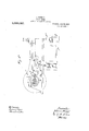
- Figures 1 and la are vertical sectional views of the cylinder and crank ends respectivelyot a steam engine according to this invention
- Fig. 2 is a hypothetical pressure volume diagram when one half of the steam passing from the high pressure cylinder is utilized in the auxiliary apparatus and the other half in the second expansion cylinder.
- Figs. 3 and 3a are side elevations respectively Of the cylinder and crank ends of the in Figs. 1 and a and 3 and 3 have been halved in order to bring them Within the dimensions of the sheet.
- the steam passes from the receiver g through the pipe 7c. and by the branch z' into the hollow covers 71A of the second expansion stage s. ot steam to this expansion stage.
- the second expansion stage 8 is illustrated .as an ordinary unidirectional tlow steam engine cylinder and lneed not-be further described. Connected with the intermediate r eiver lA and there is a pipe f leading' to any auxiliary or like apparatus g' which is shown diagrammat'ically in Fig. 3.
- auxiliary apparatus g From the auxiliary apparatus g there leads a pipe fto a ,'pfessure motor o, which responds "to varia-y icc 'Ihe valves b control the admission steam is passing to vthe auxiliary apparat Je on the eccentric p 'which operates the valves Jor the low pressure cylinder.
- valve gear illustrated constitutes no part of the present invention. and is in itself known.
- the action of the pressure motor o is to make the cut oil' in the low pressure cylinder s, later, When the pressure in the pipe j?" rises and vice versa mutans mutandis.
- the engine governor is preferably arranged to control the cut oli through ay shitting eccentric.
- l claim v l. ln a. compound engine in combination with a reizeiver forming a source ot back pressure.
- a high pressure cylinde' having; a steam inletat one end and intermediate enq haus; ports, a Working piston controlling' said exhaust ports at and near the end ot' its travel, a connection leading from said exhaust ports to said receiver, means in said piston tor exhausting' steam to said receiver after said exhaust ports have been covered by lfhe pistoni second expansion cylinder communicating with said receiver, substantially as set if th.
- a receiver in combination with the moving1 pars ot a compound engine7 a receiver forming a source of hach pressure, a high pressure cylinder having a steam inlet at .one end and intermediate exhaust ports, a Working; piston controlling said cxhz'iust ports at and near the endet its travel, a connection leading from said exhaust ports to said receiver.
- a valve in said piston adapted to establish communication between the cylinder and the exhaust ports7 means tor operating said valve to establish said communicatioi'i atiter the exhaust ports have. been covered by the pistoinsaid means being driven from a moin ing part ot' the engine and a second erpansion cylinder eoininunicating with said receiver, substantially as set forth.
- a compound engine in combination with a, receiver forming al source orf hack pressure, a high pressure cylinder, having an inlet valve at one end and intermediate exhaust ports, mechanism for operating said inlet valve9 a Working piston controlling said exhaust ports at and near the end of its travel', mechanism to control said 'inlet valve7 a pressure motor communicamting With said receiver and operable on said mechanism, a connection leading' from said ero haust ports to said receiver, means in said piston for exhausting steam to said receiver after said exhaust ports have been covered by the piston, a. second expansion cylinder communicating with said receiver, substantially yas set forth.
Landscapes
- Engineering & Computer Science (AREA)
- Mechanical Engineering (AREA)
- General Engineering & Computer Science (AREA)
- Chemical & Material Sciences (AREA)
- Combustion & Propulsion (AREA)
- Valve Device For Special Equipments (AREA)
Description
J. STUMPP.
STEAM ENGINE,
APPLIOATION FILED SEPT. 14, 1910.
,069,087 Patented July 29, 1913.
4 SHEETS-SHBLT 1.
J; STUMPF. .STEAM ENGEN'E. IAPPLICATION FILED SE-PT. 14, 1910.
www@
J. STUMPF.
STEAM ENGINE.
APPLICATION FILED SEPT.14, 1910. 1,069,087. Patented July 29, 1913.
4 SHEETS-SHEET 3.
J. STUMPP.
STEAM ENGINE. APPLICATION FILED sEPT.14, 1910.v
1,069,087, Patented July 29, 1913.
4 SHEETS-SHEET 4.
JOHANN STUMPF, OF BERLIN, GERMANY.
STEAM-ENGINE.
Specification of Letters Patent.
Patented July 29, 19i3.
Application tiled September 14, 1910. Serial No. 581,949.
T0 all whom it may concern.'
Beit known that I, JOHANN STUMPF, a subject of the KingT of Prussia, and resident of 33 Kurfrstendamm, Berlin', Germany, have invented certain new and useful Improvements in Steam-Engines, of which the following' is a specification.
This invention relates-to an improved syse tem of utilizing exhauststeam in power generating plants.
It relates more specilically to those systems in which auxiliary apparatus receives steam* from an intermediate receiver located between the first and second expansion cyling plant shown 1n Figs. 1 and la. The views der of a multiple expansion steam engine.
The object of the present invention is to l apply uni-directional flow steam engines in such a system.` Uni-directional steam flow engines are those in which the steam is admitted -at one end-and exhausts past the piston at the other end, so that once the` steam enters the cylinder it does not return on its paths. In such engines the compresi sion commences as soon as the piston, on its return stroke, covers the exhaust ports. In v order that the compression be not' excessive it is necessary to diminish the initial back pressure las much as possible. The' back pressure existing in the high pressure cylinder of a compound steam engineof the ordinary type 1s consequently inadmissible in I *the usual forms of uni-directional tiow steam the exhaust ports, so that the conditions of exhaust encountered in ordinary steam cn- `gines are assimilated while the uni-direc- .auxiliary` apparatus.
The means located in the piston for continuing the exhaust are preferably in the form of a valve operated from a moving.
part of the enginesuch as the crosshead crank or connecting rod. This enables the auxiliary exhaust to be adjusted to .givelthe vnecessary relief to the back pressure on the piston while retaining adequatecushioning.
lReferring now to the drawings which illustrate this invention in one convenient form, Figures 1 and la are vertical sectional views of the cylinder and crank ends respectivelyot a steam engine according to this invention, Fig. 2 is a hypothetical pressure volume diagram when one half of the steam passing from the high pressure cylinder is utilized in the auxiliary apparatus and the other half in the second expansion cylinder. Figs. 3 and 3a are side elevations respectively Of the cylinder and crank ends of the in Figs. 1 and a and 3 and 3 have been halved in order to bring them Within the dimensions of the sheet.
In carrying the-invention into efect according to the form illustrated, steam enters the engine by the `pipes a and passes to the` hollow covers .c whlch actas heating jackets at the inlet ends of the high pressure cylinder. This steam is admitted past the valves b `into the high'pressure cylinder. In this cylinder it expands and. propels a piston e lforward. The steam expands until the piston uncovers the exhaust ports in the cylinder walls which communicate with the exhaust receiver (1. In the form illustrated as soon as the piston e in its return stroke again covers the exhaust ports the valve d which is operated from an arm f set eccentrically on the connecting rod, establishes communication between the compression space of the cylinder and. the interior of the hollow piston e. The residual steam in the compresy sion space then passes through the hollow piston to the receiver f] as will be readily seen from Fig. l. It will be understood that the valve d may open before'the piston e covers the exhaust ports.
The steam passes from the receiver g through the pipe 7c. and by the branch z' into the hollow covers 71A of the second expansion stage s. ot steam to this expansion stage. The second expansion stage 8 is illustrated .as an ordinary unidirectional tlow steam engine cylinder and lneed not-be further described. Connected with the intermediate r eiver lA and there is a pipe f leading' to any auxiliary or like apparatus g' which is shown diagrammat'ically in Fig. 3. From the auxiliary apparatus g there leads a pipe fto a ,'pfessure motor o, which responds "to varia-y icc 'Ihe valves b control the admission steam is passing to vthe auxiliary apparat Je on the eccentric p 'which operates the valves Jor the low pressure cylinder.
The particular form of valve gear illustrated constitutes no part of the present invention. and is in itself known. The action of the pressure motor o is to make the cut oil' in the low pressure cylinder s, later, When the pressure in the pipe j?" rises and vice versa mutans mutandis.
lt will be seen that the pressure in th pipe f v1ill rise when a sutiicient excess o if) im@ g. llt an insutlicient quantity ofi steam is passing to the auxiliary apparatus the pressure in thepipe It" will fall und the cut oli in the low pressure cylinder will be earlier so thata greater proportion out the steam in the receiver 7]@ will pass to the auxiliary apparatus. rillhis process may be carried on until the entire amount of steam exhausted from the high pressure cylinder passes to the auxiliary apparatus. The lonT pressure cylinder is present not so much 'Por the purpose of obtaining the compound action as for the purpose of utilizing that excess of steam exhausted from the high pressure cylinder which is not required ,in the auxiliary apparat-us. i
Referring to the diagram in h'ig. 2 it -will be seen that in this case aboutU 50% or the steam exhausted from the high pressure cylinder repiesented by the line y is Withdrawn to the auxiliary apparatus While the steam represented by the line @c is utilized for expansion in the lov;r pressure cylinder. llith this construction the clearance space in both the cylinders may be maintained very small. ln the high pressure cylinder the clearance is shown in Fig. 2 as about 2% of the volume of the cylinder space While in the low' pressure cylinder' it is shown as amounting to 6%; ln the form illustrated it is intended that the high pressure cylinder he controlled by anvusual construction of governor so that the pressure motor o does not in any Way interfere with the ordinary i(governing of the engine. The engine governor is preferably arranged to control the cut oli through ay shitting eccentric.
It will be understood that the engine cylinders may be ailrangedgin any 'other convenient Way and many other constructional alterations may be made without departing from this invention.
l claim v l. ln a. compound engine in combination with a reizeiver forming a source ot back pressure. a high pressure cylinde' having; a steam inletat one end and intermediate enq haus; ports, a Working piston controlling' said exhaust ports at and near the end ot' its travel, a connection leading from said exhaust ports to said receiver, means in said piston tor exhausting' steam to said receiver after said exhaust ports have been covered by lfhe pistoni second expansion cylinder communicating with said receiver, substantially as set if th.
2. in combination with the moving1 pars ot a compound engine7 a receiver forming a source of hach pressure, a high pressure cylinder having a steam inlet at .one end and intermediate exhaust ports, a Working; piston controlling said cxhz'iust ports at and near the endet its travel, a connection leading from said exhaust ports to said receiver. a valve in said piston adapted to establish communication between the cylinder and the exhaust ports7 means tor operating said valve to establish said communicatioi'i atiter the exhaust ports have. been covered by the pistoinsaid means being driven from a moin ing part ot' the engine and a second erpansion cylinder eoininunicating with said receiver, substantially as set forth.
ln a compound engine in combination with a, receiver forming al source orf hack pressure, a high pressure cylinder, having an inlet valve at one end and intermediate exhaust ports, mechanism for operating said inlet valve9 a Working piston controlling said exhaust ports at and near the end of its travel', mechanism to control said 'inlet valve7 a pressure motor communicamting With said receiver and operable on said mechanism, a connection leading' from said ero haust ports to said receiver, means in said piston for exhausting steam to said receiver after said exhaust ports have been covered by the piston, a. second expansion cylinder communicating with said receiver, substantially yas set forth.
' In Witness whereof l have hereunto set my hand in the presence of two witnesses.
i JOHANN Sllllllll.
l/Vitnesses Jonaunns HEYNEMANN, FRANZ ll/lLLnR.
Priority Applications (1)
| Application Number | Priority Date | Filing Date | Title |
|---|---|---|---|
| US58194910A US1069087A (en) | 1910-09-14 | 1910-09-14 | Steam-engine. |
Applications Claiming Priority (1)
| Application Number | Priority Date | Filing Date | Title |
|---|---|---|---|
| US58194910A US1069087A (en) | 1910-09-14 | 1910-09-14 | Steam-engine. |
Publications (1)
| Publication Number | Publication Date |
|---|---|
| US1069087A true US1069087A (en) | 1913-07-29 |
Family
ID=3137325
Family Applications (1)
| Application Number | Title | Priority Date | Filing Date |
|---|---|---|---|
| US58194910A Expired - Lifetime US1069087A (en) | 1910-09-14 | 1910-09-14 | Steam-engine. |
Country Status (1)
| Country | Link |
|---|---|
| US (1) | US1069087A (en) |
-
1910
- 1910-09-14 US US58194910A patent/US1069087A/en not_active Expired - Lifetime
Similar Documents
| Publication | Publication Date | Title |
|---|---|---|
| US1069087A (en) | Steam-engine. | |
| US393597A (en) | Steam-engine | |
| US716115A (en) | Telescopic compound engine. | |
| US239494A (en) | Uei haskin | |
| US592824A (en) | Compound engine | |
| US690620A (en) | Telescopic compound engine. | |
| US406011A (en) | Compound locomotive-engine | |
| US625900A (en) | Single-expansion plunger pumping-engine | |
| US1159112A (en) | Steam-engine. | |
| US625758A (en) | Edward w | |
| US816348A (en) | Cylinder-compression-relief valve. | |
| US1494994A (en) | Steam engine | |
| US707647A (en) | Telescopic compound engine. | |
| US1826873A (en) | Diesel locomotive having power cylinders connected to the driving mechanism | |
| US678709A (en) | Semicompound telescopic engine. | |
| US338378A (en) | willans | |
| US309591A (en) | Regulating steam-supply to compound engines | |
| US678984A (en) | Steam-engine valve. | |
| US470664A (en) | Steam-engine | |
| US231007A (en) | Apparatus for compressing air | |
| US741838A (en) | Compound steam-engine. | |
| US705692A (en) | Compound locomotive-engine. | |
| US742948A (en) | Steam-engine. | |
| US1835773A (en) | Exhaust steam operated auxiliaries | |
| US1201383A (en) | Steam-engine. |