US10690750B2 - Synchronization of spatially distributed radar - Google Patents
Synchronization of spatially distributed radar Download PDFInfo
- Publication number
- US10690750B2 US10690750B2 US15/413,753 US201715413753A US10690750B2 US 10690750 B2 US10690750 B2 US 10690750B2 US 201715413753 A US201715413753 A US 201715413753A US 10690750 B2 US10690750 B2 US 10690750B2
- Authority
- US
- United States
- Prior art keywords
- mimo radar
- radar systems
- slave
- master
- signal
- Prior art date
- Legal status (The legal status is an assumption and is not a legal conclusion. Google has not performed a legal analysis and makes no representation as to the accuracy of the status listed.)
- Active, expires
Links
- 238000000034 method Methods 0.000 claims abstract description 26
- 230000005540 biological transmission Effects 0.000 claims description 12
- 238000001914 filtration Methods 0.000 claims description 3
- 238000010586 diagram Methods 0.000 description 8
- 230000000875 corresponding effect Effects 0.000 description 3
- 230000001360 synchronised effect Effects 0.000 description 3
- 230000002596 correlated effect Effects 0.000 description 2
- 230000003111 delayed effect Effects 0.000 description 2
- 238000001514 detection method Methods 0.000 description 2
- 238000010276 construction Methods 0.000 description 1
- 230000001934 delay Effects 0.000 description 1
- 230000006870 function Effects 0.000 description 1
- 238000012986 modification Methods 0.000 description 1
- 230000004048 modification Effects 0.000 description 1
- 230000010363 phase shift Effects 0.000 description 1
Images


Classifications
-
- G—PHYSICS
- G01—MEASURING; TESTING
- G01S—RADIO DIRECTION-FINDING; RADIO NAVIGATION; DETERMINING DISTANCE OR VELOCITY BY USE OF RADIO WAVES; LOCATING OR PRESENCE-DETECTING BY USE OF THE REFLECTION OR RERADIATION OF RADIO WAVES; ANALOGOUS ARRANGEMENTS USING OTHER WAVES
- G01S7/00—Details of systems according to groups G01S13/00, G01S15/00, G01S17/00
- G01S7/02—Details of systems according to groups G01S13/00, G01S15/00, G01S17/00 of systems according to group G01S13/00
- G01S7/40—Means for monitoring or calibrating
- G01S7/4004—Means for monitoring or calibrating of parts of a radar system
-
- G—PHYSICS
- G01—MEASURING; TESTING
- G01S—RADIO DIRECTION-FINDING; RADIO NAVIGATION; DETERMINING DISTANCE OR VELOCITY BY USE OF RADIO WAVES; LOCATING OR PRESENCE-DETECTING BY USE OF THE REFLECTION OR RERADIATION OF RADIO WAVES; ANALOGOUS ARRANGEMENTS USING OTHER WAVES
- G01S13/00—Systems using the reflection or reradiation of radio waves, e.g. radar systems; Analogous systems using reflection or reradiation of waves whose nature or wavelength is irrelevant or unspecified
- G01S13/003—Bistatic radar systems; Multistatic radar systems
-
- G—PHYSICS
- G01—MEASURING; TESTING
- G01S—RADIO DIRECTION-FINDING; RADIO NAVIGATION; DETERMINING DISTANCE OR VELOCITY BY USE OF RADIO WAVES; LOCATING OR PRESENCE-DETECTING BY USE OF THE REFLECTION OR RERADIATION OF RADIO WAVES; ANALOGOUS ARRANGEMENTS USING OTHER WAVES
- G01S13/00—Systems using the reflection or reradiation of radio waves, e.g. radar systems; Analogous systems using reflection or reradiation of waves whose nature or wavelength is irrelevant or unspecified
- G01S13/02—Systems using reflection of radio waves, e.g. primary radar systems; Analogous systems
- G01S13/06—Systems determining position data of a target
- G01S13/08—Systems for measuring distance only
- G01S13/32—Systems for measuring distance only using transmission of continuous waves, whether amplitude-, frequency-, or phase-modulated, or unmodulated
- G01S13/34—Systems for measuring distance only using transmission of continuous waves, whether amplitude-, frequency-, or phase-modulated, or unmodulated using transmission of continuous, frequency-modulated waves while heterodyning the received signal, or a signal derived therefrom, with a locally-generated signal related to the contemporaneously transmitted signal
- G01S13/343—Systems for measuring distance only using transmission of continuous waves, whether amplitude-, frequency-, or phase-modulated, or unmodulated using transmission of continuous, frequency-modulated waves while heterodyning the received signal, or a signal derived therefrom, with a locally-generated signal related to the contemporaneously transmitted signal using sawtooth modulation
-
- G—PHYSICS
- G01—MEASURING; TESTING
- G01S—RADIO DIRECTION-FINDING; RADIO NAVIGATION; DETERMINING DISTANCE OR VELOCITY BY USE OF RADIO WAVES; LOCATING OR PRESENCE-DETECTING BY USE OF THE REFLECTION OR RERADIATION OF RADIO WAVES; ANALOGOUS ARRANGEMENTS USING OTHER WAVES
- G01S13/00—Systems using the reflection or reradiation of radio waves, e.g. radar systems; Analogous systems using reflection or reradiation of waves whose nature or wavelength is irrelevant or unspecified
- G01S13/87—Combinations of radar systems, e.g. primary radar and secondary radar
-
- G—PHYSICS
- G01—MEASURING; TESTING
- G01S—RADIO DIRECTION-FINDING; RADIO NAVIGATION; DETERMINING DISTANCE OR VELOCITY BY USE OF RADIO WAVES; LOCATING OR PRESENCE-DETECTING BY USE OF THE REFLECTION OR RERADIATION OF RADIO WAVES; ANALOGOUS ARRANGEMENTS USING OTHER WAVES
- G01S13/00—Systems using the reflection or reradiation of radio waves, e.g. radar systems; Analogous systems using reflection or reradiation of waves whose nature or wavelength is irrelevant or unspecified
- G01S13/88—Radar or analogous systems specially adapted for specific applications
- G01S13/93—Radar or analogous systems specially adapted for specific applications for anti-collision purposes
- G01S13/931—Radar or analogous systems specially adapted for specific applications for anti-collision purposes of land vehicles
-
- H—ELECTRICITY
- H04—ELECTRIC COMMUNICATION TECHNIQUE
- H04B—TRANSMISSION
- H04B7/00—Radio transmission systems, i.e. using radiation field
- H04B7/02—Diversity systems; Multi-antenna system, i.e. transmission or reception using multiple antennas
- H04B7/04—Diversity systems; Multi-antenna system, i.e. transmission or reception using multiple antennas using two or more spaced independent antennas
- H04B7/0413—MIMO systems
Definitions
- the subject invention relates to synchronization of spatially distributed radar.
- a method of synchronizing a plurality of spatially distributed multi-input multi-output (MIMO) radar systems includes designating one of the plurality of MIMO radar systems that includes a linear frequency modulator as a master MIMO radar system, and designating each of the plurality of MIMO radar systems other than the master MIMO radar system as slave MIMO radar systems.
- Each of the slave MIMO radar systems receives an output of the linear frequency modulator through a modulator splitter.
- a synchronization signal is sent from the linear frequency modulator through the modulator splitter to each of the slave MIMO radar systems over respective cables, and a return signal is sent from each of the slave MIMO radar systems to the master MIMO radar system over the respective cables.
- a time delay between the master MIMO radar system and each of the slave MIMO radar systems is determined based on a frequency difference between the synchronization signal and the respective return signal.
- sending the synchronization signal includes sending a signal at a lower frequency than a regular signal transmitted during normal operation.
- determining the time delay includes mixing, using a mixer, the return signal from each of the slave MIMO radar systems with the synchronization signal and filtering an output of the mixer to isolate a difference between the synchronization signal and the respective return signal.
- the method also includes using the time delay to process subsequent received reflections by the master MIMO radar system and each of the slave MIMO radar systems resulting from a transmission by a transmission element of one of the slave MIMO radar systems.
- the plurality of MIMO radar systems includes a plurality of mixers each configured to mix the synchronization signal and the respective return signal of each slave MIMO radar system and a plurality of filters each configured to filter an output of the respective mixer to isolate a difference between the synchronization signal and the respective return signal.
- the processor uses the difference to determine the time delay.
- the receiver section of the master MIMO radar system uses the time delay to process subsequent received reflections resulting from a transmission by a transmission element of one of the slave MIMO radar systems.
- the platform is an automobile.
- FIG. 1 is a block diagram of a sensor scheme that includes multiple multi-input multi-output (MIMO) radar systems that are synchronized according to one or more embodiments;
- MIMO multi-input multi-output
- FIG. 2 is a block diagram of a slave MIMO radar system according to one or more embodiments
- FIG. 3 is a block diagram detailing relevant aspects of the signal processor 140 used to synchronize the MIMO radar systems according to one or more embodiments;
- Embodiments of the systems and methods detailed herein relate to synchronizing multiple MIMO radar based on a delay associated with a distance between a designated a master MIMO radar system and each slave MIMO radar system.
- the synchronization process can be performed at an intermediate frequency (e.g., on the order of 20 GHz) that is lower than the typical operating frequency of the MIMO radar systems.
- FIG. 2 is a block diagram of a slave MIMO radar system 110 - i according to one or more embodiments.
- the MIMO radar system 110 - i includes a splitter 130 that splits the LFM signal 111 that is provided by the master MIMO radar system 110 - 1 and amplified by the amplifier 135 .
- One output of the splitter 130 (the amplified LFM signal 111 ) is amplified by an amplifier 135 as the return signal 112 - i .
- This return signal 112 - i is used in the synchronization process.
- the LFM signal 111 can be on the order of 20 GHz.
- the other output of the splitter 130 is provided to the transmitter section 210 - i and the receiver section 220 - i .
- this output of the splitter 130 is of interest, and the frequency of the LFM signal 111 is the operating frequency (e.g., on the order of 77 GHz).
- the transmitter section 210 - i includes multiple transmitter elements that transmit the LFM signal 111 in turn, and the receiver section 220 - i includes multiple receiver elements that all receive reflections resulting from the transmitted signals of each of the transmitter elements.
- the receiver section 220 - i also includes other known receiver components to perform correlation of the received reflection 230 at each receiver element with the transmitted signal to obtain a processor output 240 .
- FIG. 3 is a block diagram detailing relevant aspects of the signal processor 140 used to synchronize the MIMO radar systems 110 according to one or more embodiments.
- Each of the slave MIMO radar systems 110 - i provides a return signal 112 - i to the signal processor 140 .
- FIGS. 1 and 2 indicate, no actual transmission is performed during the synchronization process. Thus, there are no reflections received by any of the MIMO radar systems 110 .
- the return signals 112 - i are the LFM signal 111 provided through the cables and returned through the cables.
- Each return signal 112 - i is multiplexed by a multiplexer 305 with the LFM signal 111 provided to the signal processor 140 through the splitter 130 .
- the processor 330 includes processing circuitry that may include an application specific integrated circuit (ASIC), an electronic circuit, a processor (shared, dedicated, or group) and memory that executes one or more software or firmware programs, a combinational logic circuit, and/or other suitable components that provide the described functionality.
- the processor 330 can provide the respective dTi 340 value to each slave MIMO radar system 110 - i for use in the processing of received reflections 230 during normal operation.
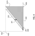
- FIG. 4 shows an exemplary LFM signal 111 and return signal 112 - i used to synchronize MIMO radar systems 110 according to one or more embodiments. Time is shown on axis 405 , and frequency is shown on axis 415 . As FIG. 4 indicates, each chirp (LFM signal 111 and output signal 112 - i ) has a time duration of Tchirp 410 , and a maximum frequency of Fmax 420 . As FIG. 4 also indicates, the time difference between transmission of the LFM signal 111 and reception of the return signal 112 - i from a slave MIMO radar system 110 is dTi 340 . This is the value of interest in the synchronization process and is given by:
- the delay dTi 340 associated with a given slave MIMO radar system 110 - i is a function of the distance L 1 i between the master MIMO radar system 110 - 1 and the given slave MIMO radar system 110 - i and the speed of light c. This value can be obtained through the shift in frequency dFi at any given time during the chirp duration Tchirp 410 that results from the delay dTi 340 .
- the frequency difference dFi is also due to the delay in the cable based on its length L 1 i.
- the return signal 112 - i is given by: Ae j(2 ⁇ (f 0 +Kt)t+ ⁇ ) [EQ. 4]
- A is the amplitude
- f 0 is the initial frequency of the LFM signal 111
- ⁇ is the phase shift due to the distance L 1 i .
- the output 315 - i is given by: Be j(2 ⁇ (KdTi)t) [EQ. 5]
- B is the amplitude, and, according to EQ.
- the frequency difference or shift dFi is given by K*dTi.
- the frequency difference dFi can be obtained from the outputs 325 - i (i.e., digitized version of outputs 315 - i ) by the processor 330 .
- the values of dFi and dTi 340 associated with each slave MIMO radar system 110 - i give the delay between the master MIMO radar system 110 - 1 and each slave MIMO radar system 110 - i .
- the delays among the slave MIMO radar systems 110 - i can then be determined with the master MIMO radar system 110 - 1 as a common reference. This synchronization process then facilitates improved processing of the received reflection at each slave MIMO radar system 110 - i.
- the dTi 340 value determined using EQ. 5 is used to process the received signal 230 at the master MIMO radar system 110 - 1 . If the received signal 230 were correlated with a non-delayed version of the LFM signal 111 transmitted by a slave MIMO radar system 110 - i , a loss of phase coherency would result. Thus, the delay due to the distance L 1 i is accounted for, and the LFM signal 111 delayed by the corresponding dTi 340 for each slave MIMO radar system 110 - i is correlated with the received signal 230 instead.
- the delay used by other slave MIMO radar systems 110 - i is determined by using the delay of each slave MIMO radar system 110 - i relative to the master MIMO radar system 110 - 1 as a reference.
Landscapes
- Engineering & Computer Science (AREA)
- Radar, Positioning & Navigation (AREA)
- Remote Sensing (AREA)
- Physics & Mathematics (AREA)
- Computer Networks & Wireless Communication (AREA)
- General Physics & Mathematics (AREA)
- Electromagnetism (AREA)
- Signal Processing (AREA)
- Radar Systems Or Details Thereof (AREA)
Abstract
Description
As EQ. 1 indicates, the
dFi=dTi*K [EQ. 2]
The slope K is constant and is given by:
Generally, the return signal 112-i is given by:
Ae j(2π(f
In EQ. 4, A is the amplitude, f0 is the initial frequency of the
Be j(2π(KdTi)t) [EQ. 5]
In EQ. 5, B is the amplitude, and, according to EQ. 2, the frequency difference or shift dFi is given by K*dTi. Thus, the frequency difference dFi can be obtained from the outputs 325-i (i.e., digitized version of outputs 315-i) by the
Claims (11)
Priority Applications (3)
| Application Number | Priority Date | Filing Date | Title |
|---|---|---|---|
| US15/413,753 US10690750B2 (en) | 2017-01-24 | 2017-01-24 | Synchronization of spatially distributed radar |
| CN201810049890.3A CN108375755B (en) | 2017-01-24 | 2018-01-18 | Synchronization of spatially distributed radars |
| DE102018101364.7A DE102018101364A1 (en) | 2017-01-24 | 2018-01-22 | SYNCHRONIZATION OF SPATIALLY DISTRIBUTED RADARS |
Applications Claiming Priority (1)
| Application Number | Priority Date | Filing Date | Title |
|---|---|---|---|
| US15/413,753 US10690750B2 (en) | 2017-01-24 | 2017-01-24 | Synchronization of spatially distributed radar |
Publications (2)
| Publication Number | Publication Date |
|---|---|
| US20180210067A1 US20180210067A1 (en) | 2018-07-26 |
| US10690750B2 true US10690750B2 (en) | 2020-06-23 |
Family
ID=62812983
Family Applications (1)
| Application Number | Title | Priority Date | Filing Date |
|---|---|---|---|
| US15/413,753 Active 2038-05-17 US10690750B2 (en) | 2017-01-24 | 2017-01-24 | Synchronization of spatially distributed radar |
Country Status (3)
| Country | Link |
|---|---|
| US (1) | US10690750B2 (en) |
| CN (1) | CN108375755B (en) |
| DE (1) | DE102018101364A1 (en) |
Cited By (2)
| Publication number | Priority date | Publication date | Assignee | Title |
|---|---|---|---|---|
| US11327152B2 (en) * | 2017-09-05 | 2022-05-10 | Robert Bosch Gmbh | FMCW radar sensor including synchronized high-frequency modules |
| US20240219515A1 (en) * | 2022-12-29 | 2024-07-04 | Nxp B.V. | Timing offset compensation in coherent distributed radar |
Families Citing this family (19)
| Publication number | Priority date | Publication date | Assignee | Title |
|---|---|---|---|---|
| DE102017125156A1 (en) * | 2017-10-26 | 2019-05-02 | Infineon Technologies Ag | Apparatus and method for processing radar signals |
| DE102018203934A1 (en) * | 2018-03-15 | 2019-09-19 | Robert Bosch Gmbh | Radar sensor system and method for operating a radar sensor system |
| EP3591434B1 (en) | 2018-07-02 | 2023-07-26 | NXP USA, Inc. | Communication unit, integrated circuits and method for clock and data synchronization |
| EP3591431B1 (en) * | 2018-07-02 | 2021-05-05 | NXP USA, Inc. | Communication unit and method for clock distribution and synchronization |
| WO2020142909A1 (en) * | 2019-01-08 | 2020-07-16 | 深圳市大疆创新科技有限公司 | Data synchronization method, distributed radar system and mobile platform |
| US11656335B2 (en) * | 2019-03-05 | 2023-05-23 | Rohde & Schwarz Gmbh & Co. Kg | System and method for detecting aircraft signatures |
| US11520030B2 (en) | 2019-03-18 | 2022-12-06 | Nxp Usa, Inc. | High resolution automotive radar system with forward and backward difference co-array processing |
| US11092683B2 (en) | 2019-03-18 | 2021-08-17 | Nxp Usa, Inc. | Distributed aperture automotive radar system with alternating master radar devices |
| US11269049B2 (en) | 2019-03-18 | 2022-03-08 | Nxp Usa, Inc. | Distributed aperture automotive radar system |
| CN110018472B (en) * | 2019-04-25 | 2020-11-10 | 中国航天系统科学与工程研究院 | Spatial synchronous scanning method for distributed networked radar system |
| US11300677B2 (en) | 2019-07-08 | 2022-04-12 | GM Global Technology Operations LLC | Automated driving systems and control logic for host vehicle velocity estimation using wide aperture radar |
| US11391829B2 (en) * | 2019-09-11 | 2022-07-19 | GM Global Technology Operations LLC | Piecewise hyperbolic waveform for code division multiple access radar system operation |
| CN110596646B (en) * | 2019-09-30 | 2024-07-12 | 南京慧尔视智能科技有限公司 | Layout and method for improving radar angular resolution based on MIMO system |
| CN111487609A (en) * | 2020-04-20 | 2020-08-04 | 中国人民解放军海军航空大学 | Multi-frequency continuous wave MIMO array radar system and its target parameter estimation method |
| EP4168821A1 (en) | 2020-06-17 | 2023-04-26 | Google LLC | Distributed radar system |
| CN114002677B (en) * | 2020-07-28 | 2025-06-06 | 华为技术有限公司 | A distributed radar |
| US11888554B2 (en) | 2020-09-23 | 2024-01-30 | Nxp Usa, Inc. | Automotive MIMO radar system using efficient difference co-array processor |
| US12065170B2 (en) | 2021-09-28 | 2024-08-20 | GM Global Technology Operations LLC | Automated driving systems and control logic for lane localization of target objects in mapped environments |
| US12014552B2 (en) | 2021-12-07 | 2024-06-18 | GM Global Technology Operations LLC | Intelligent vehicle systems and control logic for incident prediction and assistance in off-road driving situations |
Citations (11)
| Publication number | Priority date | Publication date | Assignee | Title |
|---|---|---|---|---|
| US20060202726A1 (en) * | 2004-08-11 | 2006-09-14 | Feng Lin | Fast-locking digital phase locked loop |
| US7940743B2 (en) * | 2001-11-26 | 2011-05-10 | Symeo Gmbh | Method and device for the synchronization of radio stations and a time-synchronous radio bus system |
| US8108558B2 (en) * | 2008-02-22 | 2012-01-31 | Symeo Gmbh | Circuit arrangement and method for synchronization of clocks in a network |
| US20150153445A1 (en) * | 2013-12-03 | 2015-06-04 | Nxp B.V. | Multichip automotive radar system, a radar chip for such a system, and a method of operating such a system |
| US20160025844A1 (en) * | 2014-07-23 | 2016-01-28 | Honeywell International Inc. | Frequency-modulated-continuous-wave (fmcw) radar with timing synchronization |
| US20170090015A1 (en) * | 2015-09-30 | 2017-03-30 | Texas Instruments Incorporated | Multi-Chip Transceiver Testing in a Radar System |
| US20170176583A1 (en) * | 2014-03-26 | 2017-06-22 | Symeo Gmbh | Method in a Radar System, Radar System, and/or Device of a Radar System |
| US20170227625A1 (en) * | 2005-12-15 | 2017-08-10 | Polte Corporation | Partially synchronized multilateration/trilateration method and system for positional finding using rf |
| US20180024233A1 (en) * | 2015-08-28 | 2018-01-25 | Delphi Technologies, Inc. | Bi-static radar system |
| US20180074191A1 (en) * | 2014-07-03 | 2018-03-15 | GM Global Technology Operations LLC | Centralized vehicle radar methods and systems |
| US20180149730A1 (en) * | 2016-11-26 | 2018-05-31 | Wenhua Li | Cognitive MIMO Radar with Multi-dimensional Hopping Spread Spectrum and Interference-Free Windows for Autonomous Vehicles |
Family Cites Families (6)
| Publication number | Priority date | Publication date | Assignee | Title |
|---|---|---|---|---|
| CN201373917Y (en) * | 2009-03-06 | 2009-12-30 | 武汉大学 | GPS-Based Radar Synchronizer |
| CN102821455B (en) * | 2012-07-18 | 2015-11-11 | 北京无线电计量测试研究所 | For microwave duplex transmission device and the method for synchronizing time of many base station time synchronisms |
| CN102998656B (en) * | 2012-10-11 | 2014-07-30 | 北京理工大学 | Frequency step based broadband distribution type radar time synchronizing method |
| CN103384194B (en) * | 2013-07-11 | 2016-08-10 | 浙江大学 | The phase-locked system of spatial distribution unit |
| US10627480B2 (en) * | 2014-07-17 | 2020-04-21 | Texas Instruments Incorporated | Distributed radar signal processing in a radar system |
| US9880261B2 (en) * | 2014-09-30 | 2018-01-30 | Texas Instruments Incorporated | Loopback techniques for synchronization of oscillator signal in radar |
-
2017
- 2017-01-24 US US15/413,753 patent/US10690750B2/en active Active
-
2018
- 2018-01-18 CN CN201810049890.3A patent/CN108375755B/en active Active
- 2018-01-22 DE DE102018101364.7A patent/DE102018101364A1/en active Pending
Patent Citations (11)
| Publication number | Priority date | Publication date | Assignee | Title |
|---|---|---|---|---|
| US7940743B2 (en) * | 2001-11-26 | 2011-05-10 | Symeo Gmbh | Method and device for the synchronization of radio stations and a time-synchronous radio bus system |
| US20060202726A1 (en) * | 2004-08-11 | 2006-09-14 | Feng Lin | Fast-locking digital phase locked loop |
| US20170227625A1 (en) * | 2005-12-15 | 2017-08-10 | Polte Corporation | Partially synchronized multilateration/trilateration method and system for positional finding using rf |
| US8108558B2 (en) * | 2008-02-22 | 2012-01-31 | Symeo Gmbh | Circuit arrangement and method for synchronization of clocks in a network |
| US20150153445A1 (en) * | 2013-12-03 | 2015-06-04 | Nxp B.V. | Multichip automotive radar system, a radar chip for such a system, and a method of operating such a system |
| US20170176583A1 (en) * | 2014-03-26 | 2017-06-22 | Symeo Gmbh | Method in a Radar System, Radar System, and/or Device of a Radar System |
| US20180074191A1 (en) * | 2014-07-03 | 2018-03-15 | GM Global Technology Operations LLC | Centralized vehicle radar methods and systems |
| US20160025844A1 (en) * | 2014-07-23 | 2016-01-28 | Honeywell International Inc. | Frequency-modulated-continuous-wave (fmcw) radar with timing synchronization |
| US20180024233A1 (en) * | 2015-08-28 | 2018-01-25 | Delphi Technologies, Inc. | Bi-static radar system |
| US20170090015A1 (en) * | 2015-09-30 | 2017-03-30 | Texas Instruments Incorporated | Multi-Chip Transceiver Testing in a Radar System |
| US20180149730A1 (en) * | 2016-11-26 | 2018-05-31 | Wenhua Li | Cognitive MIMO Radar with Multi-dimensional Hopping Spread Spectrum and Interference-Free Windows for Autonomous Vehicles |
Cited By (3)
| Publication number | Priority date | Publication date | Assignee | Title |
|---|---|---|---|---|
| US11327152B2 (en) * | 2017-09-05 | 2022-05-10 | Robert Bosch Gmbh | FMCW radar sensor including synchronized high-frequency modules |
| US20240219515A1 (en) * | 2022-12-29 | 2024-07-04 | Nxp B.V. | Timing offset compensation in coherent distributed radar |
| US12449507B2 (en) * | 2022-12-29 | 2025-10-21 | Nxp B.V. | Timing offset compensation in coherent distributed radar |
Also Published As
| Publication number | Publication date |
|---|---|
| CN108375755B (en) | 2022-03-01 |
| DE102018101364A1 (en) | 2018-07-26 |
| US20180210067A1 (en) | 2018-07-26 |
| CN108375755A (en) | 2018-08-07 |
Similar Documents
| Publication | Publication Date | Title |
|---|---|---|
| US10690750B2 (en) | Synchronization of spatially distributed radar | |
| US10473773B2 (en) | Time synchronization of spatially separated radars | |
| US12196847B2 (en) | Range resolution in FMCW radars | |
| US9581683B2 (en) | Delay device for checking frequency modulated continuous wave (FMCW) radar | |
| JP5382087B2 (en) | Radar equipment | |
| US20170276769A1 (en) | Radar apparatus and radar method | |
| US10649069B2 (en) | Synchronization in FMCW radar systems | |
| US10274594B2 (en) | Direct Doppler-free velocity measurement in linear frequency modulation radar | |
| US11675047B2 (en) | System and method for local oscillator drift estimation and compensation in cascaded sensors | |
| JP2014517253A (en) | FMCW radar system with multiple transmitters and beat frequency multiplex | |
| EP2788788B1 (en) | Method of determining distance and speed of fmcw radar terminals | |
| US10641884B2 (en) | Radar transceiver | |
| US12032051B2 (en) | Radar device | |
| US20240310474A1 (en) | Cascaded radar system with transmiting-vehicle reflection mitigation | |
| US11231482B2 (en) | Generate overlapping chirp transmissions with a single chirp generator | |
| KR20150134577A (en) | Apparatus and method for multi FMCW radar transceiver | |
| US20210080541A1 (en) | Method and device for compensating for phase noise | |
| EP1635192B1 (en) | Radar apparatus with DC offset correction | |
| US10690769B2 (en) | Target angle determination using vehicle radar elements with local reference signals | |
| US10942254B2 (en) | Radar device and adjusting method of radar device | |
| US11294030B2 (en) | Adaptive range-selective gain control in radar system | |
| KR20170111283A (en) | Radar apparatus | |
| JP2018119956A (en) | Radar transmitter-receiver |
Legal Events
| Date | Code | Title | Description |
|---|---|---|---|
| AS | Assignment |
Owner name: GM GLOBAL TECHNOLOGY OPERATIONS LLC, MICHIGAN Free format text: ASSIGNMENT OF ASSIGNORS INTEREST;ASSIGNORS:BILIK, IGAL;POKRASS, ALEXANDER;VILLEVAL, SHAHAR;SIGNING DATES FROM 20170113 TO 20170124;REEL/FRAME:041061/0837 |
|
| STPP | Information on status: patent application and granting procedure in general |
Free format text: NON FINAL ACTION MAILED |
|
| STPP | Information on status: patent application and granting procedure in general |
Free format text: RESPONSE TO NON-FINAL OFFICE ACTION ENTERED AND FORWARDED TO EXAMINER |
|
| STPP | Information on status: patent application and granting procedure in general |
Free format text: FINAL REJECTION MAILED |
|
| STPP | Information on status: patent application and granting procedure in general |
Free format text: PUBLICATIONS -- ISSUE FEE PAYMENT VERIFIED |
|
| STCF | Information on status: patent grant |
Free format text: PATENTED CASE |
|
| MAFP | Maintenance fee payment |
Free format text: PAYMENT OF MAINTENANCE FEE, 4TH YEAR, LARGE ENTITY (ORIGINAL EVENT CODE: M1551); ENTITY STATUS OF PATENT OWNER: LARGE ENTITY Year of fee payment: 4 |