US10690748B2 - System and method for interference detection in a RF receiver - Google Patents
System and method for interference detection in a RF receiver Download PDFInfo
- Publication number
- US10690748B2 US10690748B2 US15/670,448 US201715670448A US10690748B2 US 10690748 B2 US10690748 B2 US 10690748B2 US 201715670448 A US201715670448 A US 201715670448A US 10690748 B2 US10690748 B2 US 10690748B2
- Authority
- US
- United States
- Prior art keywords
- interference
- intermittent
- noise
- plus
- signal
- Prior art date
- Legal status (The legal status is an assumption and is not a legal conclusion. Google has not performed a legal analysis and makes no representation as to the accuracy of the status listed.)
- Active, expires
Links
Images


Classifications
-
- G—PHYSICS
- G01—MEASURING; TESTING
- G01S—RADIO DIRECTION-FINDING; RADIO NAVIGATION; DETERMINING DISTANCE OR VELOCITY BY USE OF RADIO WAVES; LOCATING OR PRESENCE-DETECTING BY USE OF THE REFLECTION OR RERADIATION OF RADIO WAVES; ANALOGOUS ARRANGEMENTS USING OTHER WAVES
- G01S7/00—Details of systems according to groups G01S13/00, G01S15/00, G01S17/00
- G01S7/02—Details of systems according to groups G01S13/00, G01S15/00, G01S17/00 of systems according to group G01S13/00
- G01S7/023—Interference mitigation, e.g. reducing or avoiding non-intentional interference with other HF-transmitters, base station transmitters for mobile communication or other radar systems, e.g. using electro-magnetic interference [EMI] reduction techniques
-
- G—PHYSICS
- G01—MEASURING; TESTING
- G01S—RADIO DIRECTION-FINDING; RADIO NAVIGATION; DETERMINING DISTANCE OR VELOCITY BY USE OF RADIO WAVES; LOCATING OR PRESENCE-DETECTING BY USE OF THE REFLECTION OR RERADIATION OF RADIO WAVES; ANALOGOUS ARRANGEMENTS USING OTHER WAVES
- G01S13/00—Systems using the reflection or reradiation of radio waves, e.g. radar systems; Analogous systems using reflection or reradiation of waves whose nature or wavelength is irrelevant or unspecified
- G01S13/88—Radar or analogous systems specially adapted for specific applications
- G01S13/93—Radar or analogous systems specially adapted for specific applications for anti-collision purposes
- G01S13/931—Radar or analogous systems specially adapted for specific applications for anti-collision purposes of land vehicles
-
- G—PHYSICS
- G01—MEASURING; TESTING
- G01S—RADIO DIRECTION-FINDING; RADIO NAVIGATION; DETERMINING DISTANCE OR VELOCITY BY USE OF RADIO WAVES; LOCATING OR PRESENCE-DETECTING BY USE OF THE REFLECTION OR RERADIATION OF RADIO WAVES; ANALOGOUS ARRANGEMENTS USING OTHER WAVES
- G01S7/00—Details of systems according to groups G01S13/00, G01S15/00, G01S17/00
- G01S7/02—Details of systems according to groups G01S13/00, G01S15/00, G01S17/00 of systems according to group G01S13/00
- G01S7/35—Details of non-pulse systems
- G01S7/352—Receivers
- G01S7/354—Extracting wanted echo-signals
-
- G01S2007/356—
-
- G—PHYSICS
- G01—MEASURING; TESTING
- G01S—RADIO DIRECTION-FINDING; RADIO NAVIGATION; DETERMINING DISTANCE OR VELOCITY BY USE OF RADIO WAVES; LOCATING OR PRESENCE-DETECTING BY USE OF THE REFLECTION OR RERADIATION OF RADIO WAVES; ANALOGOUS ARRANGEMENTS USING OTHER WAVES
- G01S7/00—Details of systems according to groups G01S13/00, G01S15/00, G01S17/00
- G01S7/02—Details of systems according to groups G01S13/00, G01S15/00, G01S17/00 of systems according to group G01S13/00
- G01S7/35—Details of non-pulse systems
- G01S7/352—Receivers
- G01S7/356—Receivers involving particularities of FFT processing
Definitions
- the present disclosure relates generally to the detection of the presence of radio frequency (RF) interference, and more specifically, to the detection of RF interference being experienced by a radar receiver.
- RF radio frequency
- a RF transceiver such as an automotive radar system.
- Possible effects include reduced ability of the RF receiver to detect objects of interest and/or to estimate relevant parameter values of those detected objects, such as object range, object bearing, and/or object Doppler.
- the reliable detection of degrading interference becomes especially important for safety-critical applications. For example, a radar mounted in the front bumper of a vehicle may be relied upon to detect objects in the path of the host vehicle. If the radar cannot perform its function within specifications due to the presence of interference, then it must notify the controlling system of this situation so that it can recover to a safe state.
- Interference may be categorized in several ways, such as continuous versus intermittent, narrowband versus wideband, etc.
- Narrowband interferers may include AM radio broadcasts and amateur radio signals. Wideband noise that extends across a large portion of the RF spectrum may also interfere. Wideband noise can be caused, for example, by electrical machinery, internal combustion engines (e.g., lawn mowers), fluorescent lights, and other sensors. Wideband interferers can be somewhat random, and may be more difficult to avoid.
- the bandwidth of a RF receiver can be approximated by the inverse of its receiver gate. For example, the bandwidth of a radar receiver having receiver gate of 400 ns is 2.5 MHz.
- An example of a wideband interference source is the RF transmission of a narrow pulse, such as having a duration of 10 ns, which would have a bandwidth of 100 MHz.
- Another example of a wideband interference source is a fast frequency chirp, such as continuous wave (CW) transmission that changes frequency in steps or continuously over a span of 200 MHz over a duration of 10 ⁇ sec.
- CW continuous wave
- thermal noise All RF receivers experience electrical fluctuations produced by internal components, which is known as thermal noise.
- SOI desired signal of interest
- the thermal noise may change with temperature, component aging and/or be inherently distinct for different radar systems.
- a significant challenge is to distinguish between the presence of degrading interference and ordinary changes in thermal noise contributions.
- the latter may be caused by changes in receiver-chain amplification, which affects the signal and noise equally, thereby not presenting a significant change in receiver functionality.
- the former causes a significant increase in receiver noise levels without the corresponding improvement in signal quality, therefore degrading the ability of the receiver to perform its intended function.
- the direct measurement of thermal noise level by the receiver is another possible technique.
- the implementation of this technique may require the presence of additional and costly receiver circuitry. It may also require the interruption of normal radar functionality in order to perform this measurement, which might be undesirable.
- the present disclosure describes embodiments of improved apparatus (e.g., a detector, receiver, etc.) and methods to detect narrowband and/or wideband interference present with a SOI in RF signal received by a RF receiver.
- the embodiments utilize automated real-time signal analysis characterizing changing densities and distributions of signal features with order statistical filtering.
- Accurate detection of interference is important to ensure proper operation of the RF receiver. For example, it can permit the generation of notification signals such as alerts or control signals for deployment of counter measures to mitigate the harmful effects of the interference.
- a counter measure would be to adjust the RF transceiver's transmission frequency plan in order to avoid or to reduce the interference.
- Another example is to activate a special operating mode that might degrade performance during normal operation, but provide a net improvement in functionality during the presence of degrading interference.
- the detected objects from an automotive radar may be used to implement an application.
- an application might be blindspot detection.
- Such applications provide an audio, visual, and/or haptic warning to alert the driver to the presence of another vehicle in the blindspot region of the driver's vehicle.
- the presence of interference could cause false alerts to the driver and/or missed alerts for actual vehicles in the blindspot region.
- interference detection can alternatively be used to determine when to disable the blindspot application and to inform the driver that the application is unavailable.
- interference detection could also be used to improve performance by, for example, activating alternative algorithms to improve application performance in the presence of interference.
- an interference alert is issued, or an interference suppression or avoidance application invoked, if an interference metric determined by the methods or apparatus described herein exceeds an alert threshold for a predetermined number of sampling cycles.
- the alert or invoked application may then be ceased if the interference metric falls below the alert threshold (e.g., immediately, or after a predetermined time, number of cycles, etc.).
- a method is provided wherein an RF signal is detected at a receiver.
- the received RF signal may include an RF SOI and potentially an intermittent interference signal occupying an interference bandwidth.
- Thermal noise of the receiver may be estimated by statistically analyzing a plurality of time intervals of spectral magnitude data of the received RF signal, including at least one spectral magnitude data interval not including the intermittent interference signal.
- Order statistics may be applied to the spectral magnitude data to estimate the thermal noise, and to estimate an intermittent-interference-plus-noise level by statistically analyzing an extended time interval of the spectral magnitude data so that the degrading interference, if present, is included in the analyzed spectral magnitude data.
- An interference metric may then be determined based on a ratio of the estimated intermittent-interference-plus-noise level to the estimated thermal noise. The interference metric may then be evaluated against one or more thresholds to detect the presence or absence of degrading RF interference.
- estimating the thermal noise comprises obtaining a frequency domain representation of the plurality of time intervals, wherein the frequency domain representation includes a magnitude level for each of a plurality of frequencies sorted in an order statistic (e.g., Rayleigh or other) distribution.
- a value may be determined associated with a thermal-noise reference percentile relative to the distribution as a raw thermal noise estimate, and the raw thermal noise estimate may be conditioned to compensate for estimation bias in order to obtain the thermal noise estimate.
- Estimating the intermittent-interference-plus-noise level may include obtaining a frequency domain representation of the extended time interval, wherein the frequency domain representation includes a magnitude level for each of a plurality of frequencies sorted in an order statistic Rayleigh distribution.
- a value may be determined associated with the reference percentile relative to the Rayleigh distribution as a raw intermittent-interference-plus-noise level estimate, and the raw intermittent-interference-plus-noise level estimate may be conditioned to compensate for estimation bias to obtain the intermittent-interference-plus-noise level estimate.
- the thermal-noise reference percentile may comprise a standard deviation percentile along the Rayleigh distribution selected to be lower than representations of RF object reflections and degrading interference in the Rayleigh distribution.
- estimate conditioning may comprise eliminating outlier and averaging remaining thermal noise or intermittent-interference-plus-noise level estimates, respectively, over several sampling cycles.
- Obtaining the frequency domain representations may further comprise respectively reducing sidelobe energies of the frequency domain representations through application of a window approximation (e.g., a Kaiser window, etc.).
- normalization techniques may be applied in order to compensate for time domain attenuation underestimations of the thermal noise and intermittent-interference-plus-noise level estimates resulting from the window approximation.
- obtaining the frequency domain representations may comprise applying a FFT of respective lengths.
- an FFT length associated with the thermal noise estimation may comprise a fraction of the number of time intervals in the plurality of time intervals
- the FFT length associated with the intermittent-interference-plus-noise level estimation may be equal to a number of time domain samples of the extended time interval.
- the use of distinct FFT lengths may result in scaling changes in the thermal noise and intermittent-interference-plus-noise level estimates. Normalization may be utilized to compensate for such operations.
- One or more parameters may be received by the RF receiver (or a detector or controller of the receiver) specifying at least one of the number of time intervals in the plurality, a number of time intervals to be discarded prior to estimating the thermal noise, an FFT length to be used in estimating the thermal noise, an FFT length to be used in estimating the interference plus noise level, and a percentile for identifying a reference percentile relative to an order statistic Rayleigh distribution of the spectral magnitude data.
- present disclosure provides an interference detector for use with an RF receiver configured to receive an RF signal including a SOI and potentially an intermittent interference signal occupying an interference bandwidth.
- the detector may include a controller and/or processor configured to operate in accordance with any of the above method embodiments.
- the RF receiver comprises an automotive radar receiver.
- the disclosure provides an RF receiver configured to detect RF interference that includes a front end configured to receive an RF signal including a SOI and potentially an intermittent interference signal occupying an interference bandwidth, and an interference detection controller and/or processor configured to operate in accordance with any of the above method embodiments.
- FIG. 1 is a schematic functional block diagram illustrating a RF sensor system in accordance with various embodiments.
- FIG. 2 is a flow diagram illustrating a method of interference detection in accordance with an embodiment of the disclosure.
- FIG. 3 is a schematic functional block diagram illustrating an embodiment of an interference detector.
- FIG. 4 is a schematic functional block diagram illustrating another perspective of an embodiment of an interference detector.
- FIGS. 5A-5C are schematic functional block diagrams illustrating components of an embodiment of an order statistic filter.
- FIGS. 6A and 6B are schematic functional block diagrams illustrating embodiments of noise conditioners.
- FIG. 7 is a schematic functional block diagram illustrating an embodiment of an interference detection metric calculator.
- FIG. 8 is a schematic functional block diagram illustrating an embodiment of interference detection logic.
- FIG. 9 is a schematic functional block diagram illustrating an embodiment of alert logic.
- FIGS. 10A-10Q are signal plots of thermal noise, interference-plus-noise and detection metrics resulting from numerous simulation testing scenarios.
- FIG. 1 illustrates an exemplary radar sensor (radar system) 100 , the sensor having two receiver channels and one transmitter channel.
- Radar sensor 100 may be configured with conventional RF components and assemblies, such as an antenna array 102 , analog front end electronics 104 , a digital front end module 106 , and a signal processing module 108 .
- Signal processing module 108 may be configured with a processor or controller 110 and an interference detector 112 that operates on a received RF signal 114 in accordance with the disclosed embodiments.
- FIG. 2 illustrates multiple steps of an interference detection method 200 in accordance with an embodiment.
- the statistical model can be used to set thresholds for satisfying interference alert and/or countermeasure initiation or cessation.
- Method 200 will be described in detail with example functional block diagrams shown in additional figures. In general, however, exemplary method 200 begins by receiving (step 202 ) the received RF signal 114 detected by radar sensor 100 .
- Received signal 114 includes an RF signal of interest (SOI) 116 , such as a reflected wave of a transmitted signal emitted by a transmitter of radar sensor 100 , and potentially an intermittent interference signal 118 occupying an interference bandwidth.
- SOI RF signal of interest
- thermal noise 205 is estimated by the interference detector 112 by statistically analyzing a plurality of short time intervals of spectral magnitude data of the received RF signal 114 , including at least one spectral magnitude data interval not including the intermittent interference signal 118 .
- the interference source cannot be continuously present during operation of the sensor 100 .
- “present” may mean detectable for at least a determined time, such as 6 ms. So, not continuously present would mean that there must be some time gaps in the presence and/or effects of the interfering source.
- an interfering source might have a repeating transmission cycle, where each cycle has example duration of 30 ms.
- a first segment of the interferer cycle might comprise 20 ms of fast frequency sweeping that causes interference to the sensor 100 .
- a second segment might comprise a pulsed segment at a single carrier frequency lasting 6 ms, which does not cause degrading interference to sensor 100 .
- a last example segment might consist of a 4 ms period of no RF transmissions.
- An interference-plus-noise level 207 may be estimated (step 206 ) by detector 112 by statistically analyzing an extended time interval of the data of received RF signal 114 , so that the degrading interference, if present, will be included in the extended time interval.
- an interference metric 209 may be determined by detector 112 based on a ratio of the estimated interference-plus-noise level 207 to the estimated thermal noise 205 .
- the interference metric 209 may be evaluated against one or more thresholds 211 to detect the presence or absence of degrading RF interference in received RF signal 114 . If the interference metric 209 exceeds the one or more thresholds 211 under conditions defined by logic of the detector 112 , an alert or other countermeasure control signal 212 may be issued by the detector 112 .
- FIG. 3 is a block diagram representation of an embodiment of an interference detector 300 (which may be very similar or identical to detector 112 ).
- interference detector 300 may be configured with two data flow channels, one of which may receive a first input data stream 304 , for example a stream of 256 time-domain samples of the received RF signal 114 received at a normal angle to an antenna array of the sensor 100 .
- a second time-domain data stream 306 corresponding to the received RF signal 114 received at a squint angle with respect to the sensor 100 antenna array may be received as input to the second data flow channel.
- the time-domain data streams 304 , 306 (which in other embodiments are not limited to normal and squint angle data streams) are each fed into respective beam interference detectors 302 A, 302 B, which in turn generate, respectively, normal-beam interference alert 308 and squint-beam interference alert 312 signals.
- Alerts signals 308 , 312 may be received by logic module 310 , which uses indication(s) of the presence of a degrading interference signal reflected in the values of the alert signals 308 , 312 to determine whether to issue an interference alert 312 (or other counter measure control signal).
- FIG. 4 is a block diagram showing in more detail functional components of an embodiment of an interference detector 400 , i.e., implementing 302 A and/or 302 B.
- the time-domain data samples 304 , 306 are received at DC removal module 402 where average values of any DC signals present in the samples are removed.
- the output from DC removal module 402 is split into separate noise and interference-plus-noise signal processing data flows.
- the signal processing channels employ order statistics (OS) in OS filters 404 , 406 to respectively generate raw noise estimate ⁇ m 408 and raw interference plus noise estimate ⁇ ri+n 410 , and conditioning (at conditioners 412 , 414 ) to generate conditioned noise estimate ⁇ cn 416 and conditioned interference plus noise estimates ⁇ ci+n 418 that are used by detection metric calculator 420 to determine an interference-plus-noise to noise ratio 422 .
- OS are advantageous because they are directly related to the underlying distribution and are robust in the presence of outliers.
- Detection logic 424 uses the detection metric 422 to determine whether a degrading interfering signal has been detected; i.e., a raw detection signal 426 is output from detection logic 424 . Additional alert logic 428 then determines whether alert conditions have been met, and if so, an interference alert 430 (or countermeasure control signal) is output.
- FIG. 5A illustrates in more detail the operation of an OS filter 500 , such as OS filter 404 which is used to estimate thermal noise 205 and OS filter 406 used to estimate interference plus noise in received RF signal 114 .
- OS filter 500 utilizes Rayleigh probability distribution 502 and a number of process control parameters whose values depend upon whether thermal noise 205 or interference plus noise level 207 is being estimated. The significance of the example parameter values shown in Table One will be described below.
- Blanker 506 discards all but N samples of the data 504 , wherein parameter N 508 is selected based on whether thermal noise 205 or interference 207 is being estimated. In the exemplary embodiment, if thermal noise 205 is to be estimated, all 256 data samples are utilized. If interference level 207 is to be estimated, half (e.g., 128 ) of the data samples may be discarded.
- a goal of using a larger N time interval sample set for estimating thermal noise 205 is to include for analysis at least one time interval in which the intermittent interference signal is not present, so that the interfering signal and the RF SOI do not mask one another at identical or overlapping frequencies.
- Blanker 506 then output N time-domain samples 510 to STFTM module 512 .
- STFTM module 512 performs a non-overlapping short-time Fourier transform magnitude operation on the N time-domain samples 510 , resulting in a frequency domain representation of the time interval data including a magnitude level for each of a plurality of frequencies at which signals are present in the received RF signal 114 .
- STFTM module 512 utilizes two additional inputs, a FFT length parameter 514 and a window function 516 .
- FFT length parameter 514 may be selected to be short for thermal noise estimation, to increase the number of transform operations and the probability that no interfering signal is present in the analyzed time interval data. In contrast, in estimating interference, FFT length parameter 514 may be selected to be an extended time interval, e.g., equal to the number N of the time domain samples 510 .
- Window function 516 is generated by window module 518 , which accepts as an input the FFT length parameter 514 and window type parameter 520 (e.g., a Kaiser window, etc.). Window function 516 operates to reduce sidelobe energies of the frequency domain representations of the spectral data resulting from the STFTM window approximation operation.
- STFTM spectral output data 522 is then sorted by magnitude in ascending order by sorting function 524 .
- Sorted spectral magnitude data 526 is then passed from sorting function 524 to Rayleigh parameter estimator 528 .
- the Rayleigh parameter estimator 528 operates (as described in detail below) to generate a raw sigma estimate a. 534 , which could comprise raw noise ⁇ m 408 or raw interference plus noise ⁇ ri+n 410 of FIG. 4 , depending upon which variance is being estimated in the particular embodiment of OS filter 500 .
- Rayleigh parameter estimator 528 In order to generate raw sigma estimate ⁇ raw 534 , parameter estimator 528 first iteratively generates an unscaled estimate ⁇ unscaled 550 at Rayleigh statistic converter 536 , and then performs FFT normalization 552 and window normalization 554 on unscaled estimate ⁇ unscaled 550 to obtain the raw sigma estimate ⁇ raw 534 .
- Rayleigh parameter estimator 528 estimates the raw sigma estimate ⁇ raw 534 under which the assumption that the sorted spectral data 526 is a random variable having a Rayleigh distribution (as shown in FIG. 5A ).
- the Rayleigh distribution has one parameter, ⁇ , which is the same as being estimated by the Rayleigh parameter estimator 528 , i.e., raw sigma estimate 534 .
- the sorted spectral data 526 may include signal components that disturb the Rayleigh distribution.
- Non-arithmetic estimates are plotted against distribution 502 to illustrate different “modes” in the spectrum. Each mode corresponds to a single component in the receive RF signal, including the desired RF SOI 116 and the degrading interference signal 118 .
- An advantageous operating principle of the order statistics analyses utilized in the embodiments is the data populating the left-most portion of the probability distribution plot 502 comprises predominantly, if not exclusively, thermal noise 205 or interference plus noise data.
- Rayleigh statistic converter 536 receives as an initial input the reference percentile parameter 532 (e.g., 5% of the probability distribution) and the sorted spectral magnitude data 526 .
- Rayleigh statistic converter 536 represents a function that generates and iteratively refines the accuracy of unscaled estimate ⁇ unscaled 550 based on these inputs and measures of bias present in the instant estimate. As shown in FIG.
- Rayleigh statistic converter 536 initializes (block 541 ) a counter and initializes (block 542 ) an adjusted percentile raw estimate to the input reference percentile parameter 532 .
- An iterative process (blocks 538 and 544 ) is then performed to remove any corruption bias that may be present in the raw estimate a. 534 due to the presence of outliers (e.g., from reflected target objects signals, interference, etc.) in the Rayleigh distribution 502 . For example, if half of the sorted spectral magnitude data 526 are corrupted by outliers, this could cause roughly a 10% error in the raw estimate ⁇ raw 534 .
- the raw estimate ⁇ raw 534 is recalculated (in block 538 ) iteratively with adjustments in an adjusted reference percentile 532 ′.
- an iteration counter is checked (block 540 ), and if the counter has not exceeded a defined threshold (e.g., 3 iterations), a current bias is determined (block 545 ) by investigating the actual rank of a three standard deviation (3 ⁇ ) value in the sorted and plotted spectral magnitude plot 502 and adjusting (blocks 546 and 548 ) the adjusted reference percentile 532 ′ such that the 3 ⁇ value represents a 99 th percentile in the sorted spectral magnitude plot 502 .
- the iterative loop counter is also incremented in block 547 .
- the bias removal process ceases and Rayleigh statistic converter 536 outputs the current unscaled estimate ⁇ unscaled 550 , whereupon it undergoes FFT normalization 552 and window normalization 554 .
- FFT normalization 552 compensates for scaling introduced by using different FFT lengths in STFTM module 512 .
- the unscaled a estimate 550 is multiplied by a correction factor comprising the inverse square root of the FFT length parameter 514 .
- Window normalization 554 applies a noise-loss correction factor to compensate for underestimation error introduced in the time domain by the application of window function 516 .
- the output of window normalization is a compensated raw noise estimate arm 534 .
- OS filters 404 , 406 output respectively raw noise estimate am 408 and raw interference plus noise estimate ⁇ ri+n 410 .
- the raw noise estimate ⁇ m 408 is output on each cycle of the RF receiver to noise conditioner 412 , details of which are shown in FIG. 6A .
- noise conditioner 412 gathers raw noise estimates ⁇ m 408 (block 602 ) over a predefined number (e.g., 8) of RF receiver cycles, and selects for output the minimum value of the collected set, i.e., the noise a least corrupted by noise of interference.
- FIG. 6B shows details of the operation of an embodiment of interference conditioner 414 , which receives raw interference plus noise estimate ⁇ ri+n 410 over a similar number of RF receiver cycles and performs a 25% trimmed mean operation thereupon. That is, from the (exemplary) 8 samples received, interference conditioner 414 discards the largest two values and the two smallest values, and outputs as the conditioned interference plus noise estimate ⁇ ci+n 418 the average of the remaining input samples.
- conditioned noise estimate a. 416 and conditioned interference plus noise estimate ⁇ ci+n 418 are passed to detection metric calculator 420 , exemplary functions of an embodiment of which are shown in FIG. 7 .
- DMC 420 computes (blocks 702 , 704 ) a ratio of the two values, applies a maximum operator (block 706 ) to reduce fluctuations in the ratio, and converts (block 708 ) the ratio in decibel (dB) units.
- DMC 420 outputs the detection metric 422 .
- the detection metric 422 is then passed to detection logic 424 of the interference detector 400 .
- An example embodiment of detection logic 424 is shown in FIG.
- detection logic 424 compares the detection metric 422 to respective values of an “On” threshold 802 and an “Off” threshold 804 , and outputs raw detection state signal 426 that indicates the current state (i.e., On, Off, or indeterminate state where no changes to current actions is to be taken.)
- the detection state signal 426 may be passed to alert logic 428 of the interference detector 400 , as shown in FIG. 4 . Alternatively, the detection state signal 426 may immediately trigger or cease an alert or an invoked countermeasure application.
- Alert logic 428 is shown in FIG. 9 , wherein the raw detection signal 426 and a counter 902 may be utilized to introduce RF receiver cycle-based delays by only taking actions, such as turning on or off alerts or countermeasures, after a predefined number of cycles in which a change in the raw detection signal 426 has been encountered.
- Interference detectors in accordance with the embodiments provide reliable detection of degrading interference in mild (e.g., receiver noise floor increases of 12-24 dB) to severe (e.g., 36 dB or greater increases) interference conditions. The incidences of false alarms given during conditions of no interference are extremely low.
- RF detection scenario parameters such as numbers of target objects superposed in a region of interest being sensed by the sensor 100 , object radar cross section, object ranges (from the sensor 100 ), object velocities, no interference conditions, and conditions of intermittent interference comprising an interference model including a repeating pattern of transmission followed by radio silence formed by adding a complex Gaussian random variable to each time-domain sample collected during any transmission period.
- receiver parameters such as thermal noise standard deviations, IQ balance, and ADC quantization.
- Consistent transmission waveforms from the sensor 100 and interference control parameters i.e., numbers of spectral data samples, noise and interference FFT lengths, noise percentile, window type, and detection thresholds, etc. were utilized.
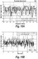
- FIG. 10A shows an example of spectral magnitude values 1000 from which a 5% thermal noise reference percentile parameter was collected.
- the x-axis indicates frequency translated to Doppler in units of meters/second for a particular radar sensor.
- the y-axis provides spectral magnitude in decibels.
- FIG. 10A shows 17 separate spectra, one corresponding to a 128-point FFT used for interference estimation, and the remaining corresponding to the 16-point FFTs used for estimating thermal noise. These spectral values correspond to FFT normalization 522 of FIG. 5A .
- FIG. 10A shows an example of spectral magnitude values 1000 from which a 5% thermal noise reference percentile parameter was collected.
- the x-axis indicates frequency translated to Doppler in units of meters/second for a particular radar sensor.
- the y-axis provides spectral magnitude in decibels.
- FIG. 10A shows 17 separate spectra, one corresponding to a 128-point FFT used for interference estimation, and the
- the estimated noise levels 1002 a , 1004 a are consistent with the scenario parameters.
- FIG. 10C shows, for the same scenario, a detection metric 1006 a (such as previously described metric 422 ) over time.
- On detection threshold 1010 e.g., threshold 802
- Off detection threshold 1012 e.g., threshold 804
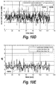
- FIGS. 10D and 10E show, for a scenario of higher thermal noise (i.e., std dev of 10, versus 1 in the previous scenario) and no interference, the resulting noise levels 1002 b , 1004 b (e.g., corresponding to estimates 418 and 416 respectively) are correspondingly higher, but the detection metric 1006 b is not disturbed by the higher noise level.
- thermal noise i.e., std dev of 10 versus 1 in the previous scenario
- the resulting noise levels 1002 b , 1004 b e.g., corresponding to estimates 418 and 416 respectively
- the detection metric 1006 b is not disturbed by the higher noise level.
- FIGS. 10F and 10G show resulting signals for a scenario of low thermal noise (std dev 1), and no interference, but in the presence of a single 10 m 2 target object at 4.5 m range and moving at 2.6 m/s.
- the noise levels 1002 c , 1004 c are centered about the stdev 1 axis, and the detection metric 1006 c remains undisturbed by the presence of the target object.
- FIGS. 10H and 10I shown resulting signals for a scenario of low thermal noise and no interference, but in the presence of sixteen (16) 10 m 2 target objects. Again, the noise level 1002 d , 1004 d are commensurate with input noise, and the detection metric 1006 d remains undisturbed by the presence of numerous target objects.
- a higher conditioned interference plus noise estimate 1002 e is shown, separate from the conditioned noise estimate 1004 e .
- the interference detection metric 1006 e now indicates the presence of the interfering signal, rising above both the On detection threshold 1010 and Off detection threshold 1012 .
- the detection metric 1006 f is not disturbed by the severe IQ imbalance. False alarms are not generated, as the detection metric 1006 f is well below the On threshold 1010 and only exceeds the Off threshold 1012 briefly.
- the noise levels 1002 g , 1004 g are increased equally, the detection metric 1006 g is not disturbed, and no false alarms are generated.
- FIGS. 10P and 10Q show resulting signals for a scenario of low thermal noise, in the presence of no interference, but in the presence of a massively large (1000 m 2 ) target object, at close range (0.5 m) and impossibly fast acceleration (1000 m/s 2 ). There is a slight separation between the lower conditioned interference plus noise estimate 1002 h and the conditioned noise estimate 1004 h , but the detection metric 1006 h is not significantly disturbed, and no false alarms are issued.
- RF receivers, detectors and methods may be implemented in digital electronic circuitry, in computer hardware, firmware, and/or software.
- the implementation can be as a computer program product (i.e., a computer program tangibly embodied in an information carrier).
- the implementation can, for example, be in a machine-readable storage device and/or in a propagated signal, for execution by, or to control the operation of, data processing apparatus.
- the implementation can, for example, be a programmable processor, a computer, and/or multiple computers.
- a computer program can be written in any form of programming language, including compiled and/or interpreted languages, and the computer program can be deployed in any form, including as a stand-alone program or as a subroutine, element, and/or other unit suitable for use in a computing environment.
- a computer program can be deployed to be executed on one computer or on multiple computers at one site.
- Method steps can be performed by one or more programmable processors and/or controllers executing a computer program to perform functions of the invention by operating on input data and generating output. Method steps can also be performed by, and an apparatus can be implemented as, special purpose logic circuitry.
- the circuitry can, for example, be a FPGA (field programmable gate array) and/or an ASIC (application-specific integrated circuit). Modules, subroutines, and software agents can refer to portions of the computer program, the processor, the special circuitry, software, and/or hardware, e.g., a controller such as a microcontroller, which implements that functionality.
- processors suitable for the execution of a computer program include, by way of example, both general and special purpose microprocessors, and any one or more processors of any kind of digital computer.
- a processor receives instructions and data from a read-only memory or a random access memory or both.
- the essential elements of a computer are a processor for executing instructions and one or more memory devices for storing instructions and data.
- a computer can be operatively coupled to receive data from and/or transfer data to one or more mass storage devices for storing data, e.g., magnetic, magneto-optical disks, or optical disks.
- Data transmission and instructions can also occur over a communications network.
- Information carriers suitable for embodying computer program instructions and data include all forms of non-volatile memory, including by way of example semiconductor memory devices.
- the information carriers can, for example, be EPROM, EEPROM, flash memory devices, magnetic disks, internal hard disks, removable disks, magneto-optical disks, CD-ROM, and/or DVD-ROM disks.
- the processor and the memory can be supplemented by and/or incorporated in special purpose logic circuitry.
- the above described techniques can be implemented on a computer having a display device.
- the display device can, for example, be a cathode ray tube (CRT) and/or a liquid crystal display (LCD) monitor.
- CTR cathode ray tube
- LCD liquid crystal display
- the interaction with a user can, for example, be a display of information to the user and a keyboard and a pointing device, e.g., a mouse or a trackball, by which the user can provide input to the computer, e.g., interact with a user interface element.
- Other kinds of devices can be used to provide for interaction with a user.
- Other devices can, for example, be feedback provided to the user in any form of sensory feedback, e.g., visual feedback, auditory feedback, or tactile feedback.
- Input from the user can, for example, be received in any form, including acoustic, speech, and/or tactile input.
- the above described techniques can be implemented in a distributed computing system that includes a back-end component.
- the back-end component can, for example, be a data server, a middleware component, and/or an application server.
- the above described techniques can be implemented in a distributing computing system that includes a front-end component.
- the front-end component can, for example, be a client computer having a graphical user interface, a Web browser through which a user can interact with an example implementation, and/or other graphical user interfaces for a transmitting device.
- the components of the system can be interconnected by any form or medium of digital data communication, e.g., a communication network. Examples of communication networks include a local area network (LAN), a wide area network (WAN), the Internet, wired networks, and/or wireless networks.
- LAN local area network
- WAN wide area network
- the Internet wired networks, and/or wireless networks.
- the system can include clients and servers.
- a client and a server are generally remote from each other and typically interact through a communication network.
- the relationship of client and server arises by virtue of computer programs running on the respective computers and having a client-server relationship to each other.
- Packet-based networks can include, for example, the Internet, a carrier internet protocol (IP) network, e.g., local area network (LAN), wide area network (WAN), campus area network (CAN), metropolitan area network (MAN), home area network (HAN)), a private IP network, an IP private branch exchange (IPBX), a wireless network, e.g., radio access network (RAN), 802.11 network, 802.16 network, general packet radio service (GPRS) network, HiperLAN), and/or other packet-based networks.
- IP carrier internet protocol
- LAN local area network
- WAN wide area network
- CAN campus area network
- MAN metropolitan area network
- HAN home area network
- IP network IP private branch exchange
- wireless network e.g., radio access network (RAN), 802.11 network, 802.16 network, general packet radio service (GPRS) network, HiperLAN
- RAN radio access network
- 802.11 802.11 network
- 802.16 general packet radio service
- GPRS general packet radio service
- Circuit-based networks can include, for example, the public switched telephone network (PSTN), a private branch exchange (PBX), a wireless network, e.g., RAN, Bluetooth, code-division multiple access (CDMA) network, time division multiple access (TDMA) network, global system for mobile communications (GSM) network), and/or other circuit-based networks.
- PSTN public switched telephone network
- PBX private branch exchange
- CDMA code-division multiple access
- TDMA time division multiple access
- GSM global system for mobile communications
- the computing system can also include one or more computing devices.
- a computing device can include, for example, a computer, a computer with a browser device, a telephone, an IP phone, a mobile device, e.g., cellular phone, personal digital assistant (PDA) device, laptop computer, electronic mail device, and/or other communication devices.
- the browser device includes, for example, a computer, e.g., desktop computer, laptop computer, with a World Wide Web browser, e.g., Microsoft® Internet Explorer® available from Microsoft Corporation, Mozilla® Firefox available from Mozilla Corporation.
- the mobile computing device includes, for example, a Blackberry®, iPAD®, iPhone® or other smartphone device.
Landscapes
- Engineering & Computer Science (AREA)
- Radar, Positioning & Navigation (AREA)
- Remote Sensing (AREA)
- Computer Networks & Wireless Communication (AREA)
- Physics & Mathematics (AREA)
- General Physics & Mathematics (AREA)
- Electromagnetism (AREA)
- Radar Systems Or Details Thereof (AREA)
Abstract
Description
| TABLE ONE |
| OS Filter Process Parameter Values |
| Thermal Noise | Interference | |||
| Parameter | | Estimator | ||
| N | ||||
| 256 | 128 | |||
| |
16 | 128 | ||
| Window Type | | Kaiser12 | ||
| Percentile | ||||
| 5% | 5% | |||
Claims (23)
Priority Applications (3)
| Application Number | Priority Date | Filing Date | Title |
|---|---|---|---|
| US15/670,448 US10690748B2 (en) | 2017-08-07 | 2017-08-07 | System and method for interference detection in a RF receiver |
| PCT/US2018/044986 WO2019032371A1 (en) | 2017-08-07 | 2018-08-02 | System and method for interference detection in a rf receiver |
| EP18755659.2A EP3665494B1 (en) | 2017-08-07 | 2018-08-02 | System and method for interference detection in a rf receiver |
Applications Claiming Priority (1)
| Application Number | Priority Date | Filing Date | Title |
|---|---|---|---|
| US15/670,448 US10690748B2 (en) | 2017-08-07 | 2017-08-07 | System and method for interference detection in a RF receiver |
Publications (2)
| Publication Number | Publication Date |
|---|---|
| US20190041492A1 US20190041492A1 (en) | 2019-02-07 |
| US10690748B2 true US10690748B2 (en) | 2020-06-23 |
Family
ID=63209725
Family Applications (1)
| Application Number | Title | Priority Date | Filing Date |
|---|---|---|---|
| US15/670,448 Active 2038-06-22 US10690748B2 (en) | 2017-08-07 | 2017-08-07 | System and method for interference detection in a RF receiver |
Country Status (3)
| Country | Link |
|---|---|
| US (1) | US10690748B2 (en) |
| EP (1) | EP3665494B1 (en) |
| WO (1) | WO2019032371A1 (en) |
Cited By (2)
| Publication number | Priority date | Publication date | Assignee | Title |
|---|---|---|---|---|
| US11044028B2 (en) | 2018-07-12 | 2021-06-22 | Silicon Laboratories Inc. | Apparatus for radio-frequency receiver with interference detection and associated methods |
| US11811574B2 (en) | 2022-01-19 | 2023-11-07 | Texas Instruments Incorporated | Detection of in-band interference |
Families Citing this family (12)
| Publication number | Priority date | Publication date | Assignee | Title |
|---|---|---|---|---|
| CN110912626B (en) * | 2019-10-31 | 2022-04-12 | 西南电子技术研究所(中国电子科技集团公司第十研究所) | Method for evaluating communication anti-interference performance of measurement and control system |
| EP3828585B1 (en) * | 2019-11-26 | 2023-08-23 | Arriver Software AB | Vehicle control in severe radar interference conditions |
| WO2022139783A1 (en) * | 2020-12-21 | 2022-06-30 | Intel Corporation | High end imaging radar |
| CN113176543B (en) * | 2021-03-26 | 2022-06-24 | 上海卫星工程研究所 | Radio frequency interference suppression method and system based on multi-dimensional information combination |
| CN113917409B (en) * | 2021-09-30 | 2024-12-06 | 中国船舶集团有限公司第七二四研究所 | A broadband interference identification method based on real-time spectrum analysis |
| CN114401526B (en) * | 2021-12-16 | 2024-11-01 | 天津七一二通信广播股份有限公司 | Narrow-band interference position detection method and system based on double threshold decision |
| US12196844B2 (en) * | 2022-04-15 | 2025-01-14 | Gm Cruise Holdings Llc | Radar interference detection and mitigation |
| CN115902391A (en) * | 2022-10-21 | 2023-04-04 | 湖南艾科诺维科技有限公司 | A Dynamic Threshold Signal Detection Method Based on Morphological Filtering and Eigenvalue Decomposition |
| CN116125419A (en) * | 2023-01-12 | 2023-05-16 | 电子科技大学 | A Method for Intermittent Sampling Disturbance Parameter Estimation Based on Multi-Domain Transform Deep Learning |
| CN116973849B (en) * | 2023-06-05 | 2026-03-03 | 西北工业大学 | SAR image radio frequency interference suppression method based on spectrum outlier detection |
| CN120143088B (en) * | 2025-05-15 | 2025-08-22 | 中国人民解放军海军航空大学 | Constant false alarm rate control method, system, terminal and storage medium for radar target detection based on sample quantile characteristics |
| CN121325112B (en) * | 2025-12-16 | 2026-02-27 | 伽利略(天津)技术有限公司 | Radar dynamic anti-interference method and system based on interference source positioning |
Citations (11)
| Publication number | Priority date | Publication date | Assignee | Title |
|---|---|---|---|---|
| US20020094044A1 (en) * | 2001-01-16 | 2002-07-18 | Kolze Thomas J. | System and method for canceling interference in a communication system |
| US20030030583A1 (en) * | 2001-08-06 | 2003-02-13 | Finn James S. | System and method of emergency apparatus pre-deployment using impulse radio radar |
| US6690746B1 (en) * | 1999-06-11 | 2004-02-10 | Southwest Research Institute | Signal recognizer for communications signals |
| US20040258178A1 (en) * | 2001-11-27 | 2004-12-23 | Valery Leblond | Method of detecting and processing pulsed signals in a radio signal |
| US20050088335A1 (en) * | 2003-07-03 | 2005-04-28 | Stephens Scott A. | Synthetic aperture radar system and method for local positioning |
| US20060152405A1 (en) | 2005-01-13 | 2006-07-13 | M/A Com, Inc. | Vehicle sensor system and process |
| US20080182543A1 (en) * | 2007-01-26 | 2008-07-31 | Samsung Electronics Co., Ltd. | Method for receiving signal in communication system and system therefor |
| EP2390679A1 (en) * | 2010-05-27 | 2011-11-30 | Mitsubishi Electric R&D Centre Europe B.V. | Automotive radar with radio-frequency interference avoidance |
| US20150070204A1 (en) | 2013-09-06 | 2015-03-12 | Fujitsu Limited | Detection and ranging apparatus |
| US20150145718A1 (en) * | 2013-04-18 | 2015-05-28 | Watherlink Co., Ltd. | Radar weather data signal processing method and signal processing module |
| US9182476B2 (en) | 2009-04-06 | 2015-11-10 | Conti Temic Microelectronic Gmbh | Radar system having arrangements and methods for the decoupling of transmitting and receiving signals and for the suppression of interference radiation |
-
2017
- 2017-08-07 US US15/670,448 patent/US10690748B2/en active Active
-
2018
- 2018-08-02 EP EP18755659.2A patent/EP3665494B1/en active Active
- 2018-08-02 WO PCT/US2018/044986 patent/WO2019032371A1/en not_active Ceased
Patent Citations (12)
| Publication number | Priority date | Publication date | Assignee | Title |
|---|---|---|---|---|
| US6690746B1 (en) * | 1999-06-11 | 2004-02-10 | Southwest Research Institute | Signal recognizer for communications signals |
| US20020094044A1 (en) * | 2001-01-16 | 2002-07-18 | Kolze Thomas J. | System and method for canceling interference in a communication system |
| US20030030583A1 (en) * | 2001-08-06 | 2003-02-13 | Finn James S. | System and method of emergency apparatus pre-deployment using impulse radio radar |
| US20040258178A1 (en) * | 2001-11-27 | 2004-12-23 | Valery Leblond | Method of detecting and processing pulsed signals in a radio signal |
| US20050088335A1 (en) * | 2003-07-03 | 2005-04-28 | Stephens Scott A. | Synthetic aperture radar system and method for local positioning |
| US20060152405A1 (en) | 2005-01-13 | 2006-07-13 | M/A Com, Inc. | Vehicle sensor system and process |
| US20080182543A1 (en) * | 2007-01-26 | 2008-07-31 | Samsung Electronics Co., Ltd. | Method for receiving signal in communication system and system therefor |
| US9182476B2 (en) | 2009-04-06 | 2015-11-10 | Conti Temic Microelectronic Gmbh | Radar system having arrangements and methods for the decoupling of transmitting and receiving signals and for the suppression of interference radiation |
| EP2390679A1 (en) * | 2010-05-27 | 2011-11-30 | Mitsubishi Electric R&D Centre Europe B.V. | Automotive radar with radio-frequency interference avoidance |
| US8471760B2 (en) | 2010-05-27 | 2013-06-25 | Mitsubishi Electric Corporation | Automotive radar with radio-frequency interference avoidance |
| US20150145718A1 (en) * | 2013-04-18 | 2015-05-28 | Watherlink Co., Ltd. | Radar weather data signal processing method and signal processing module |
| US20150070204A1 (en) | 2013-09-06 | 2015-03-12 | Fujitsu Limited | Detection and ranging apparatus |
Non-Patent Citations (4)
| Title |
|---|
| "Order Statistic", Internet Citation, May 4, 2017, Retrieved from the Internet: URL:https://en.wikipedia.org/w/index.php?title=Order_statistic&oldid=778658493. |
| "Radar CFAR Thresholding in Clutter and Multiple Target Situations;" Hermann Rohling; IEEE Transactions on Aerospace and Electronic Systems; vol. AES-19, No. 4; Jul. 1983. |
| "Rayleigh Distribution", Jun. 19, 2017, Retrieved from the Internet: URL:https://en.wikipedia.org/w/index.php?title=Rayleigh_distribution&oldid=786515437. |
| Invitation to Pay Additional Fees, Communication Relating to the Results of the Partial International Search, and Provisional Opinion Accompanying the Partial Search Result in corresponding International Application No. PCT/US2018/044986, dated Nov. 6, 2018; 30 pages. |
Cited By (4)
| Publication number | Priority date | Publication date | Assignee | Title |
|---|---|---|---|---|
| US11044028B2 (en) | 2018-07-12 | 2021-06-22 | Silicon Laboratories Inc. | Apparatus for radio-frequency receiver with interference detection and associated methods |
| US11888540B2 (en) | 2018-07-12 | 2024-01-30 | Silicon Laboratories Inc. | Apparatus for radio-frequency receiver with interference detection and associated methods |
| US11811574B2 (en) | 2022-01-19 | 2023-11-07 | Texas Instruments Incorporated | Detection of in-band interference |
| US12284068B2 (en) | 2022-01-19 | 2025-04-22 | Texas Instruments Incorporated | Detection of in-band interference |
Also Published As
| Publication number | Publication date |
|---|---|
| US20190041492A1 (en) | 2019-02-07 |
| EP3665494A1 (en) | 2020-06-17 |
| EP3665494B1 (en) | 2024-10-16 |
| WO2019032371A1 (en) | 2019-02-14 |
Similar Documents
| Publication | Publication Date | Title |
|---|---|---|
| US10690748B2 (en) | System and method for interference detection in a RF receiver | |
| Garry et al. | Evaluation of direct signal suppression for passive radar | |
| EP3796037B1 (en) | Detecting motion based on reference signal transmissions | |
| JP6363637B2 (en) | System and method for detecting spoofing of radio signals | |
| US20170090013A1 (en) | Apparatus and method for attenuating close-range radar signals in an automotive radar sensor | |
| CN107462873B (en) | Radar interference rapid identification method | |
| EP3489710A1 (en) | Radar interference suppression | |
| US10288726B2 (en) | Impulse noise detection and removal for radar and communication systems | |
| US10451728B2 (en) | Apparatus and method for attenuating close-range radar signals with balancing for dual-frequency difference in radar signals in an automotive radar sensor | |
| Ahmed | Novel noncoherent radar pulse integration to combat noise jamming | |
| Wang et al. | Time-frequency jammer mitigation based on Kalman filter for GNSS receivers | |
| Wang et al. | Improved characterization of GNSS jammers using short-term time-frequency Rényi entropy | |
| US20250076452A1 (en) | Radar signal interference mitigation with generative networks | |
| Lu et al. | Robust distributed sonar CFAR detection based on modified VI-CFAR detector | |
| CN109738876A (en) | A kind of maneuvering target method for parameter estimation based on acceleration compensation | |
| Ramakrishnan et al. | Adaptive radar detection in doubly nonstationary autoregressive doppler spread clutter | |
| Qi et al. | Interrupted Sampling Repeater Jamming Recognition Method Based on Wavelet Packet Transform | |
| Watts et al. | Coherent radar performance in sea clutter | |
| Jawad et al. | PRI characteristics analysis under complex environment of spurious and missing observations | |
| Ciesielski | Polynomial-Based Detector for Passive Radar Operating in the DVB-T Band | |
| KR101221142B1 (en) | Method and apparatus for estimating source location of radar pulse | |
| Seo et al. | An Analysis of CFAR Thresholds and Scale Factors with Window Effects in Pulse Compression | |
| Saliu et al. | Performance analysis of a modified otsu-based constant false alarm rate (CFAR) algorithm under varying signal to noise ratio in radar systems | |
| Khader | Enhanced performance of fh detection system using adaptive threshold level | |
| Li et al. | An Interference Elimination and Coherent Accumulation Method for Narrowband Aiming Jamming Based on FCM-IAA |
Legal Events
| Date | Code | Title | Description |
|---|---|---|---|
| AS | Assignment |
Owner name: AUTOLIV ASP, INC., UTAH Free format text: ASSIGNMENT OF ASSIGNORS INTEREST;ASSIGNOR:PARADIE, MICHAEL;REEL/FRAME:043241/0982 Effective date: 20170803 |
|
| STPP | Information on status: patent application and granting procedure in general |
Free format text: DOCKETED NEW CASE - READY FOR EXAMINATION |
|
| AS | Assignment |
Owner name: VEONEER US, INC., MICHIGAN Free format text: ASSIGNMENT OF ASSIGNORS INTEREST;ASSIGNOR:AUTOLIV ASP, INC.;REEL/FRAME:046326/0137 Effective date: 20180608 |
|
| STPP | Information on status: patent application and granting procedure in general |
Free format text: NON FINAL ACTION MAILED |
|
| STPP | Information on status: patent application and granting procedure in general |
Free format text: RESPONSE TO NON-FINAL OFFICE ACTION ENTERED AND FORWARDED TO EXAMINER |
|
| STPP | Information on status: patent application and granting procedure in general |
Free format text: FINAL REJECTION MAILED |
|
| STPP | Information on status: patent application and granting procedure in general |
Free format text: NOTICE OF ALLOWANCE MAILED -- APPLICATION RECEIVED IN OFFICE OF PUBLICATIONS |
|
| STPP | Information on status: patent application and granting procedure in general |
Free format text: PUBLICATIONS -- ISSUE FEE PAYMENT VERIFIED |
|
| STCF | Information on status: patent grant |
Free format text: PATENTED CASE |
|
| AS | Assignment |
Owner name: VEONEER US, LLC, DELAWARE Free format text: CHANGE OF NAME;ASSIGNOR:VEONEER US, INC.;REEL/FRAME:061069/0535 Effective date: 20220401 |
|
| AS | Assignment |
Owner name: VEONEER US, LLC, MICHIGAN Free format text: AFFIDAVIT / CHANGE OF ADDRESS;ASSIGNOR:VEONEER US, LLC;REEL/FRAME:065049/0150 Effective date: 20220426 |
|
| MAFP | Maintenance fee payment |
Free format text: PAYMENT OF MAINTENANCE FEE, 4TH YEAR, LARGE ENTITY (ORIGINAL EVENT CODE: M1551); ENTITY STATUS OF PATENT OWNER: LARGE ENTITY Year of fee payment: 4 |
|
| AS | Assignment |
Owner name: MAGNA ELECTRONICS, LLC, MICHIGAN Free format text: CHANGE OF NAME;ASSIGNOR:VEONEER US, LLC;REEL/FRAME:067234/0861 Effective date: 20230928 |