US10690595B2 - Optical sensing device, method of manufacturing the same, and optical sensing method - Google Patents
Optical sensing device, method of manufacturing the same, and optical sensing method Download PDFInfo
- Publication number
- US10690595B2 US10690595B2 US16/319,155 US201716319155A US10690595B2 US 10690595 B2 US10690595 B2 US 10690595B2 US 201716319155 A US201716319155 A US 201716319155A US 10690595 B2 US10690595 B2 US 10690595B2
- Authority
- US
- United States
- Prior art keywords
- light beam
- polarization
- polarization light
- reflected
- sensing
- Prior art date
- Legal status (The legal status is an assumption and is not a legal conclusion. Google has not performed a legal analysis and makes no representation as to the accuracy of the status listed.)
- Expired - Fee Related
Links
- 230000003287 optical effect Effects 0.000 title claims abstract description 142
- 238000000034 method Methods 0.000 title claims description 44
- 238000004519 manufacturing process Methods 0.000 title claims description 6
- 238000002198 surface plasmon resonance spectroscopy Methods 0.000 claims abstract description 61
- 230000001902 propagating effect Effects 0.000 claims description 16
- 230000010287 polarization Effects 0.000 abstract description 133
- 239000000523 sample Substances 0.000 description 32
- 238000001514 detection method Methods 0.000 description 29
- 230000027455 binding Effects 0.000 description 21
- 238000009739 binding Methods 0.000 description 21
- 102000053602 DNA Human genes 0.000 description 17
- 108020004414 DNA Proteins 0.000 description 17
- 238000005259 measurement Methods 0.000 description 13
- 230000004044 response Effects 0.000 description 13
- 239000012266 salt solution Substances 0.000 description 12
- PCHJSUWPFVWCPO-UHFFFAOYSA-N gold Chemical compound [Au] PCHJSUWPFVWCPO-UHFFFAOYSA-N 0.000 description 10
- 239000010931 gold Substances 0.000 description 10
- 229910052737 gold Inorganic materials 0.000 description 10
- 102000004169 proteins and genes Human genes 0.000 description 10
- 108090000623 proteins and genes Proteins 0.000 description 10
- 102000008100 Human Serum Albumin Human genes 0.000 description 8
- 108091006905 Human Serum Albumin Proteins 0.000 description 8
- 230000008859 change Effects 0.000 description 8
- 239000000090 biomarker Substances 0.000 description 6
- 229940079593 drug Drugs 0.000 description 6
- 239000003814 drug Substances 0.000 description 6
- 239000000463 material Substances 0.000 description 6
- 230000003993 interaction Effects 0.000 description 5
- 230000035945 sensitivity Effects 0.000 description 5
- 238000012512 characterization method Methods 0.000 description 4
- 239000012530 fluid Substances 0.000 description 4
- 239000011521 glass Substances 0.000 description 4
- CPBQJMYROZQQJC-UHFFFAOYSA-N helium neon Chemical compound [He].[Ne] CPBQJMYROZQQJC-UHFFFAOYSA-N 0.000 description 4
- 238000002965 ELISA Methods 0.000 description 3
- 239000002253 acid Substances 0.000 description 3
- 102000036639 antigens Human genes 0.000 description 3
- 108091007433 antigens Proteins 0.000 description 3
- 230000008569 process Effects 0.000 description 3
- 229960005080 warfarin Drugs 0.000 description 3
- 238000003556 assay Methods 0.000 description 2
- 238000002474 experimental method Methods 0.000 description 2
- 238000001502 gel electrophoresis Methods 0.000 description 2
- 238000002347 injection Methods 0.000 description 2
- 239000007924 injection Substances 0.000 description 2
- 238000004949 mass spectrometry Methods 0.000 description 2
- 229910052751 metal Inorganic materials 0.000 description 2
- 239000002184 metal Substances 0.000 description 2
- 230000009149 molecular binding Effects 0.000 description 2
- 238000012545 processing Methods 0.000 description 2
- XLYOFNOQVPJJNP-UHFFFAOYSA-N water Substances O XLYOFNOQVPJJNP-UHFFFAOYSA-N 0.000 description 2
- 238000001262 western blot Methods 0.000 description 2
- 241000894006 Bacteria Species 0.000 description 1
- 208000035473 Communicable disease Diseases 0.000 description 1
- 102000004190 Enzymes Human genes 0.000 description 1
- 108090000790 Enzymes Proteins 0.000 description 1
- 206010028980 Neoplasm Diseases 0.000 description 1
- 238000010521 absorption reaction Methods 0.000 description 1
- 238000007792 addition Methods 0.000 description 1
- 229910052782 aluminium Inorganic materials 0.000 description 1
- XAGFODPZIPBFFR-UHFFFAOYSA-N aluminium Chemical compound [Al] XAGFODPZIPBFFR-UHFFFAOYSA-N 0.000 description 1
- 239000000427 antigen Substances 0.000 description 1
- 238000013459 approach Methods 0.000 description 1
- 230000008901 benefit Effects 0.000 description 1
- 239000007853 buffer solution Substances 0.000 description 1
- 238000001444 catalytic combustion detection Methods 0.000 description 1
- 239000011248 coating agent Substances 0.000 description 1
- 238000000576 coating method Methods 0.000 description 1
- 230000002860 competitive effect Effects 0.000 description 1
- 238000011161 development Methods 0.000 description 1
- 238000003745 diagnosis Methods 0.000 description 1
- 201000010099 disease Diseases 0.000 description 1
- 208000037265 diseases, disorders, signs and symptoms Diseases 0.000 description 1
- 238000007876 drug discovery Methods 0.000 description 1
- 230000000694 effects Effects 0.000 description 1
- 239000007850 fluorescent dye Substances 0.000 description 1
- 238000001215 fluorescent labelling Methods 0.000 description 1
- 208000019622 heart disease Diseases 0.000 description 1
- 238000003384 imaging method Methods 0.000 description 1
- 238000002372 labelling Methods 0.000 description 1
- 238000002493 microarray Methods 0.000 description 1
- 238000012775 microarray technology Methods 0.000 description 1
- 238000005457 optimization Methods 0.000 description 1
- 239000013610 patient sample Substances 0.000 description 1
- 238000002360 preparation method Methods 0.000 description 1
- 230000004850 protein–protein interaction Effects 0.000 description 1
- 238000011160 research Methods 0.000 description 1
- 150000003839 salts Chemical class 0.000 description 1
- 238000007423 screening assay Methods 0.000 description 1
- 150000003384 small molecules Chemical class 0.000 description 1
- 238000001179 sorption measurement Methods 0.000 description 1
- 238000012916 structural analysis Methods 0.000 description 1
- 239000000126 substance Substances 0.000 description 1
- 238000011410 subtraction method Methods 0.000 description 1
- PJVWKTKQMONHTI-UHFFFAOYSA-N warfarin Chemical compound OC=1C2=CC=CC=C2OC(=O)C=1C(CC(=O)C)C1=CC=CC=C1 PJVWKTKQMONHTI-UHFFFAOYSA-N 0.000 description 1
Images


Classifications
-
- G—PHYSICS
- G01—MEASURING; TESTING
- G01N—INVESTIGATING OR ANALYSING MATERIALS BY DETERMINING THEIR CHEMICAL OR PHYSICAL PROPERTIES
- G01N21/00—Investigating or analysing materials by the use of optical means, i.e. using sub-millimetre waves, infrared, visible or ultraviolet light
- G01N21/17—Systems in which incident light is modified in accordance with the properties of the material investigated
- G01N21/55—Specular reflectivity
- G01N21/552—Attenuated total reflection
- G01N21/553—Attenuated total reflection and using surface plasmons
-
- G—PHYSICS
- G01—MEASURING; TESTING
- G01J—MEASUREMENT OF INTENSITY, VELOCITY, SPECTRAL CONTENT, POLARISATION, PHASE OR PULSE CHARACTERISTICS OF INFRARED, VISIBLE OR ULTRAVIOLET LIGHT; COLORIMETRY; RADIATION PYROMETRY
- G01J3/00—Spectrometry; Spectrophotometry; Monochromators; Measuring colours
- G01J3/02—Details
- G01J3/0205—Optical elements not provided otherwise, e.g. optical manifolds, diffusers, windows
- G01J3/0224—Optical elements not provided otherwise, e.g. optical manifolds, diffusers, windows using polarising or depolarising elements
-
- G—PHYSICS
- G01—MEASURING; TESTING
- G01J—MEASUREMENT OF INTENSITY, VELOCITY, SPECTRAL CONTENT, POLARISATION, PHASE OR PULSE CHARACTERISTICS OF INFRARED, VISIBLE OR ULTRAVIOLET LIGHT; COLORIMETRY; RADIATION PYROMETRY
- G01J3/00—Spectrometry; Spectrophotometry; Monochromators; Measuring colours
- G01J3/28—Investigating the spectrum
- G01J3/447—Polarisation spectrometry
-
- G—PHYSICS
- G01—MEASURING; TESTING
- G01J—MEASUREMENT OF INTENSITY, VELOCITY, SPECTRAL CONTENT, POLARISATION, PHASE OR PULSE CHARACTERISTICS OF INFRARED, VISIBLE OR ULTRAVIOLET LIGHT; COLORIMETRY; RADIATION PYROMETRY
- G01J4/00—Measuring polarisation of light
-
- G—PHYSICS
- G01—MEASURING; TESTING
- G01N—INVESTIGATING OR ANALYSING MATERIALS BY DETERMINING THEIR CHEMICAL OR PHYSICAL PROPERTIES
- G01N21/00—Investigating or analysing materials by the use of optical means, i.e. using sub-millimetre waves, infrared, visible or ultraviolet light
- G01N21/17—Systems in which incident light is modified in accordance with the properties of the material investigated
- G01N21/21—Polarisation-affecting properties
-
- G—PHYSICS
- G01—MEASURING; TESTING
- G01N—INVESTIGATING OR ANALYSING MATERIALS BY DETERMINING THEIR CHEMICAL OR PHYSICAL PROPERTIES
- G01N33/00—Investigating or analysing materials by specific methods not covered by groups G01N1/00 - G01N31/00
- G01N33/48—Biological material, e.g. blood, urine; Haemocytometers
- G01N33/50—Chemical analysis of biological material, e.g. blood, urine; Testing involving biospecific ligand binding methods; Immunological testing
- G01N33/53—Immunoassay; Biospecific binding assay; Materials therefor
- G01N33/543—Immunoassay; Biospecific binding assay; Materials therefor with an insoluble carrier for immobilising immunochemicals
- G01N33/54366—Apparatus specially adapted for solid-phase testing
- G01N33/54373—Apparatus specially adapted for solid-phase testing involving physiochemical end-point determination, e.g. wave-guides, FETS, gratings
-
- G—PHYSICS
- G01—MEASURING; TESTING
- G01N—INVESTIGATING OR ANALYSING MATERIALS BY DETERMINING THEIR CHEMICAL OR PHYSICAL PROPERTIES
- G01N21/00—Investigating or analysing materials by the use of optical means, i.e. using sub-millimetre waves, infrared, visible or ultraviolet light
- G01N21/17—Systems in which incident light is modified in accordance with the properties of the material investigated
- G01N21/21—Polarisation-affecting properties
- G01N21/211—Ellipsometry
- G01N2021/212—Arrangement with total internal reflection
-
- G—PHYSICS
- G01—MEASURING; TESTING
- G01N—INVESTIGATING OR ANALYSING MATERIALS BY DETERMINING THEIR CHEMICAL OR PHYSICAL PROPERTIES
- G01N21/00—Investigating or analysing materials by the use of optical means, i.e. using sub-millimetre waves, infrared, visible or ultraviolet light
- G01N21/75—Systems in which material is subjected to a chemical reaction, the progress or the result of the reaction being investigated
- G01N21/77—Systems in which material is subjected to a chemical reaction, the progress or the result of the reaction being investigated by observing the effect on a chemical indicator
- G01N2021/7753—Reagent layer on photoelectrical transducer
-
- G—PHYSICS
- G01—MEASURING; TESTING
- G01N—INVESTIGATING OR ANALYSING MATERIALS BY DETERMINING THEIR CHEMICAL OR PHYSICAL PROPERTIES
- G01N21/00—Investigating or analysing materials by the use of optical means, i.e. using sub-millimetre waves, infrared, visible or ultraviolet light
- G01N21/01—Arrangements or apparatus for facilitating the optical investigation
- G01N21/03—Cuvette constructions
- G01N21/05—Flow-through cuvettes
Definitions
- aspects of this disclosure relate to optical sensing devices and/or methods of manufacturing the same. Various aspects of this disclosure relate to optical sensing methods.
- protein biomarkers have been gaining rapid research interests. Early disease diagnosis and treatment response assessment are made possible with the detection of protein biomarker expression levels in patient samples. Protein biomarkers for cancers, heart diseases and infectious diseases have been reported to date. Characterization of the activity and binding kinetics of the protein biomarkers allow for structural analysis, development of screening assays and lead optimization.
- micro-array technology has recently also become an effective alternative for biomarker profiling.
- Common strategies for antibody microarray detection includes direct target labeling, sandwich assay, and competitive adsorption assay, in which fluorescent labeling, secondary antibodies or enzyme are required in the detection process. Different fluorescently labeled molecules or secondary antibodies are required for each array elements in the antibody array detection.
- SPR Surface plasmon resonance
- the optical sensing device may include an optical arrangement configured to provide a first polarization light beam and a second polarization light beam.
- the optical sensing device may also include a first optical member including a sensing surface, the first optical member configured to receive the first and second polarization light beams and reflect the first and second polarization light beams at the sensing surface.
- the optical sensing device may further include a second optical member arranged to receive the reflected first and second polarization light beams from the first optical member and configured to separate the reflected first and second polarization light beams in a first direction and a second direction, respectively.
- the optical device may additionally include a detector arrangement configured to detect the reflected first and second polarization light beams from the second optical member.
- Various embodiments may provide a method of manufacturing an optical sensing device based on surface plasmon resonance (SPR).
- the method may include providing an optical arrangement configured to provide a first polarization light beam and a second polarization light beam.
- the method may also include providing a first optical member including a sensing surface, the first optical member configured to receive the first and second polarization light beams and reflect the first and second polarization light beams at the sensing surface.
- the method may further include providing a second optical member arranged to receive the reflected first and second polarization light beams from the first optical member and configured to separate the reflected first and second polarization light beam in a first direction and a second direction, respectively.
- the method may also include providing a detector arrangement configured to detect the reflected first and second polarization light beams from the second optical member.
- Various embodiments may provide an optical sensing method based on surface plasmon resonance (SPR).
- the method may include providing a sample on a first optical member, the first optical member including a sensing surface on which the sample is provided.
- the method may also include providing, by an optical arrangement, a first polarization light beam and a second polarization light beam to the first optical member.
- the method may further include reflecting the first and second polarization light beams at the sensing surface to provide a reflected first polarization light beam and a reflected second polarization light beam.
- the method may additionally include separating, by a second optical member, the reflecting first and second polarization light beams received from the first optical member in a first direction and a second direction, respectively.
- the method may also include detecting, by a detector arrangement, the reflected first and second polarization light beams from the second optical member.
- FIG. 1 provides an illustration of an optical sensing device based on surface plasmon resonance (SPR) according to various embodiments.
- SPR surface plasmon resonance
- FIG. 2 provides an illustration of a method of manufacturing an optical sensing device based on surface plasmon resonance (SPR) according to various embodiments.
- SPR surface plasmon resonance
- FIG. 3 provides an illustration of an optical sensing method based on surface plasmon resonance (SPR) according to various embodiments.
- FIG. 4 shows a schematic of an optical sensing device according to various embodiments.
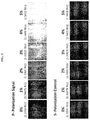
- FIG. 5 show images from the sensing signal and reference signal with varying concentrations of salt solution introduced to the sensing surface according to various embodiments.
- FIG. 6 is a plot of differential intensity (in arbitrary units or a.u.) as a function of refractive index (in refractive index units or RIU) showing the variation of the surface plasmon resonance (SPR) response curve of the device according to various embodiments with salt solution concentrations varying from about 0% to about 5%.
- SPR surface plasmon resonance
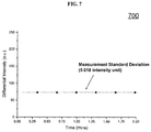
- FIG. 7 is a plot of differential intensity (in arbitrary units or a.u.) as a function of time (in minutes or mins) showing characterization of the measurement stability of the device according to various embodiments with about 2% salt solution injection.
- FIG. 8A is a plot of intensity (in arbitrary units from 0 to 255) as a function of time (in minutes or mins) showing experimental results on H3N2 antigen-antibody binding detection according to various embodiments.
- FIG. 8B is a plot of intensity (in arbitrary units from 0 to 255) as a function of time (in minutes or mins) showing experimental results on deoxyribonucleic acid (DNA)—deoxyribonucleic acid (DNA) binding detection according to various embodiments.
- FIG. 8C is a plot of intensity (in arbitrary units from 0 to 255) as a function of time (in minutes or mins) showing experimental results on human serum albumin (HAS) protein—Warfarin binding detection according to various embodiments.
- HAS human serum albumin
- Embodiments described in the context of one of the methods or optical sensing devices are analogously valid for the other methods or optical sensing devices. Similarly, embodiments described in the context of a method are analogously valid for an optical sensing device, and vice versa.
- a first layer “over” a second layer may refer to the first layer directly on the second layer, or that the first layer and the second layer are separated by one or more intervening layers.
- optical sensing device as described herein may be operable in various orientations, and thus it should be understood that the terms “top”, “bottom”, etc., when used in the following description are used for convenience and to aid understanding of relative positions or directions, and not intended to limit the orientation of the optical sensing device.
- the articles “a”, “an” and “the” as used with regard to a feature or element include a reference to one or more of the features or elements.
- the term “about” or “approximately” as applied to a numeric value encompasses the exact value and a reasonable variance.
- FIG. 1 provides an illustration of an optical sensing device 100 based on surface plasmon resonance (SPR) according to various embodiments.
- the optical sensing device 100 may include an optical arrangement 102 configured to provide a first polarization light beam and a second polarization light beam.
- the optical sensing device 100 may also include a first optical member 104 including a sensing surface, the first optical member 104 configured to receive the first and second polarization light beams and reflect the first and second polarization light beams at the sensing surface.
- the optical sensing device 100 may further include a second optical member 106 arranged to receive the reflected first and second polarization light beams from the first optical member 104 and configured to separate the reflected first and second polarization light beams in a first direction and a second direction, respectively.
- the optical device 100 may additionally include a detector arrangement 108 configured to detect the reflected first and second polarization light beams from the second optical member 106 .
- the optical sensing device 100 may include an optical arrangement 102 configured to provide beams with different polarizations.
- the polarized beams may be incident onto the sensing surface of a first optical member.
- a sample may be on the sensing surface, and the sensing surface may reflect different polarized beams differently due to the sample.
- the optical sensing device 100 may further include a second optical member 106 which separates the reflected polarized light in different directions, as well as a detector arrangement 108 configured to detect the reflected polarized light.
- the first polarized light beam may have a polarization that is orthogonal to a polarization of the second polarized light beam.
- the first polarization light beam may be a p-polarization light beam and the second polarization may be an s-polarization light beam.
- the optical arrangement 102 may include a light source configured for emitting a light beam comprising a first polarization component and a second polarization component, and a third optical member arranged to receive the light beam from the light source and configured to separate the light beam into the first polarization light beam and the second polarization light beam.
- the third optical member may be a beam splitter.
- the first polarization light beam may have the first polarization component
- the second polarization light beam may have the second polarization component.
- the first polarization component may be p-polarization
- the second polarization component may be s-polarization.
- the light source may be configured to be at a predetermined orientation for emitting the light beam including the first polarization component and the second polarization component.
- the light beam may have a predetermined wavelength or range of wavelengths.
- the first polarization light beam and the second polarization light beam may also be at the predetermined wavelength range of wavelengths.
- the light source may be a laser, such as a helium-neon (HeNe) laser.
- HeNe helium-neon
- the intensity ratio between p- and s-polarization can be selected/configured by laser orientation.
- the predetermined orientation may be about 1° to about 45° from an orientation of the light source which produces a light beam without the second polarization component.
- the light source may be rotated or oriented at angle selected from a range of 1° to about 45° from a reference orientation in which the light source emits only the first polarization.
- the predetermined orientation of the light source may be at an angle from an orientation of the light source which produces a light beam without the second polarization component (i.e., an angle from the orientation for pure p-polarization laser emission).
- the laser beam provides both p- and s-polarization components (at the predetermined orientation).
- the angle can be set at about 1° to about 45°. When the angle is less than 45°, it may enhance the intensity of the p-polarization light and may suppress the s-polarization intensity, which in turn enhances the signal to noise ratio in SPR detection.
- the first optical member 104 may include a prism, and the sensing surface is provided on a base of the prism.
- the prism may be configured to allow the first polarization light and the second polarization light to pass through.
- the prism may be transparent to light at the predetermined wavelength or range of wavelengths.
- the prism may be a glass prism, and the sensing surface may be a metal surface, such as a gold surface.
- the first optical member 104 may also include a flow cell, which may be configured to provide the sample to the sensing surface.
- the flow cell may include an inlet and an outlet. During operation, a fluid carrying the sample may be introduced into the flow cell so that the sample may be provided to the sensing surface. The fluid may then exit the flow cell through the outlet.
- the second optical member 106 may be a polarizing beam splitter.
- the polarizing beam splitter may be used to split/separate the p- and s-polarization in two different optical paths and no polarizer may be required. For example, in other conventional configurations, no polarizing beam splitter is used.
- the second optical member 106 may be configured to split or separate the reflected first and second polarization light beams in the first direction and the second direction, which may be different directions.
- the polarizing beam splitter may be made of or may include two glass prisms.
- the polarizing beam splitter may be a half-silvered mirror, or a sheet of glass or plastic with a transparently thin coating of metal, such as aluminum.
- the detector arrangement 108 may include a first detector arranged to detect the reflected first polarization light beam and a second detector arranged to detect the reflected second polarization light beam.
- the first detector and the second detector may be charge-coupled devices (CCD), or may be any other suitable detectors, such as photodiodes or phototransistors.
- the first polarization light beam may be modifiable by a surface plasmon wave propagating at the sensing surface during surface plasmon resonance (SPR) and may define a sensing signal.
- the second polarization light beam may at least be substantially unmodifiable by the surface plasmon wave propagating at the sensing surface during surface plasmon resonance (SPR) and may define a reference signal.
- the first polarization light beam may be modified or may be affected by the surface plasmon wave to a greater extent or degree compared to the second polarization light beam.
- the second polarization light beam may be modifiable and may define the sensing signal, while the first polarization light may be substantially unmodifiable, or may less modified or less affected by the surface plasmon wave, and may define the reference signal.
- the optical sensing device 100 may additionally include a processor, such as a computer, communicatively coupled to the detector arrangement 108 , the processor configured to provide a sensing output based on a difference between the reflected first and second polarization light beams.
- the difference is a difference in an intensity of the (reflected) first polarization light beam and an intensity of the second (reflected) polarization light beam.
- the intensity of the (reflected) first polarization light beam may be detected by the first detector and the intensity of the second (reflected) polarization light beam may be detected by the second detector.
- the processor may be communicatively coupled to the detector arrangement 108 via an analog-to-digital converter, such as a frame-grabber converter.
- the analog-to-digital converter or the frame-grabber converter may have one or more inputs coupled to the detector arrangement 108 , and one or more outputs coupled to the processor.
- the analog-to-digital converter or frame-grabber converter may be configured to convert an analog signal to digital signal for computer processing.
- the analog-to-digital converter or frame-grabber converter may be configured to receive a first analog signal from a first detector, and may be configured to convert the first analog signal to a first digital signal.
- the analog-to-digital converter or frame-grabber converter may be further configured to receive a second analog signal from a second detector, and may be configured to convert the second analog signal to a second digital signal.
- the processor may be configured to receive the first digital signal and the second digital signal.
- the processor may be configured to provide a sensing output based on a difference between the reflected first and second polarization light beams.
- the sensing output may be obtained by the subtraction or difference between the reflected first and second polarization light beams (i.e., p- and s-polarization light beams). From the polarization based subtraction method, experimental results may show that the sensor resolution has been improved to about 10 ⁇ 7 RIU.
- the sensing output may be based on the first digital signal and the second digital signal.
- the sensing surface may include a receptor such as an antigen protein, a surface probe deoxyribonucleic acid (DNA), or a protein (e.g. a human serum albumin (HSA protein).
- the receptor may be immobilized or attached to the sensing surface.
- the sample may include a molecule such as an antibody, a DNA, or a drug, which may be bound to the receptor upon the sample provided to the sensing surface.
- the binding of the sample with the receptor may change or generate a surface plasmon propagating at the sensing surface, which may generate or change the sensing signal and/or the reference signal. For instance, when the sample binds with a receptor, a surface plasmon propagating at the sensing surface may be changed, and the sensing signal may be increased, thus increasing the sensing output.
- the first optical member 104 may include a single flow cell.
- the differential intensity measurement between the p- and s-polarization light can be performed between the p- and s-polarization light of the same sensing surface. This may advantageously provide improved signal to noise ratio in SPR detection.
- the differential approach is between 1) signal from the sample chamber and 2) signal from the water reference chamber. This may be undesirable since two flow cell chambers are required to work together for SPR detection.
- FIG. 2 provides an illustration of a method of manufacturing an optical sensing device based on surface plasmon resonance (SPR) according to various embodiments.
- the method may include, in 202 , providing an optical arrangement configured to provide a first polarization light beam and a second polarization light beam.
- the method may also include, in 204 , providing a first optical member including a sensing surface, the first optical member configured to receive the first and second polarization light beams and reflect the first and second polarization light beams at the sensing surface.
- the method may further include, in 206 , providing a second optical member arranged to receive the reflected first and second polarization light beams from the first optical member and configured to separate the reflected first and second polarization light beam in a first direction and a second direction, respectively.
- the method may also include, in 208 , providing a detector arrangement configured to detect the reflected first and second polarization light beams from the second optical member.
- the method may include arranging the optical arrangement, the first optical member, the second optical member, and the detector arrangement in such a way so that the first optical member receives the first and second polarization light beams from the optical arrangement, reflects the first and second polarization light beams at the sensing surface to the second optical member, the second optical member receives the reflected first and second polarization light beams, and separates the reflected first and second polarization light beams in two directions, and the detector arrangement detects the reflected first and second polarization light beams traveling along the two directions.
- the method steps shown in FIG. 2 may not necessarily be in sequence.
- the first optical member may be provided before providing the optical arrangement, i.e. step 204 may be before step 202 .
- the first polarization light beam may be a p-polarization light beam and the second polarization may be an s-polarization light beam.
- the optical arrangement may include a light source configured for emitting a light beam comprising a first polarization component and a second polarization component, and a third optical member arranged to receive the light beam from the light source and configured to separate the light beam into the first polarization light beam and the second polarization light beam.
- the light source may be configured to be at a predetermined orientation for emitting the light beam including the first polarization component and the second polarization component.
- the predetermined orientation may be about 1° to about 45° from an orientation of the light source which produces a light beam without the second polarization component.
- the first optical member may include a prism, and the sensing surface may be provided on a base of the prism.
- the detector arrangement may include a first detector arranged to detect the reflected first polarization light beam and a second detector arranged to detect the reflected second polarization light beam.
- the first polarization light beam may be modifiable by a surface plasmon wave propagating at the sensing surface during SPR and defines a sensing signal
- the second polarization light beam may be at least substantially unmodifiable by the surface plasmon wave propagating at the sensing surface during SPR and may define a reference signal
- the method may further include a processor communicatively coupled to the detector arrangement, the processor configured to provide a sensing output based on a difference between an intensity of the reflected first and second polarization light beams.
- FIG. 3 provides an illustration of an optical sensing method based on surface plasmon resonance (SPR) according to various embodiments.
- the method may include, in 302 , providing a sample on a first optical member, the first optical member including a sensing surface on which the sample is provided.
- the method may also include, in 304 , providing, by an optical arrangement, a first polarization light beam and a second polarization light beam to the first optical member.
- the method may further include, in 306 , reflecting the first and second polarization light beams at the sensing surface to provide a reflected first polarization light beam and a reflected second polarization light beam.
- the method may additionally include, in 308 , separating, by a second optical member, the reflecting first and second polarization light beams received from the first optical member in a first direction and a second direction, respectively.
- the method may also include, in 310 , detecting, by a detector arrangement, the reflected first and second polarization light beams from the second optical member.
- the method may include supplying or directing a sample to a sensing surface of the first optical member, and providing a first polarization light beam and a second polarization light beam to the first optical member so that the first polarization light beam and second polarization light beam are reflected at the sensing surface.
- the reflected first polarization light beam and the reflected second polarization light beam are directed in different directions by the second optical member, and detected by the detector arrangement.
- the method may also include providing a receptor on the optical member, e.g. to the sensing surface.
- the receptor may be provided before providing the sample.
- the receptor may be a biological entity or molecule such as an antigen protein, a surface probe deoxyribonucleic acid (DNA), or a protein (e.g. a human serum albumin (HSA protein).
- the receptor may be immobilized or attached to the sensing surface.
- the sample may include a biological entity or molecule such as an antibody, a DNA, or a drug.
- the sample may be bound to the receptor upon the sample provided to the sensing surface.
- the binding of the sample with the receptor may change or generate a surface plasmon propagating at the sensing surface, which may generate or change the sensing signal and/or the reference signal. For instance, when the sample binds with a receptor, a surface plasmon propagating at the sensing surface may be changed, and the sensing signal may be increased, thus increasing the sensing output.
- the first polarization light beam and the second polarization light beam to the first optical member may be provided to the first optical member after the sample is provided to the first optical member.
- the first polarization light beam may be modifiable by a surface plasmon wave propagating at the sensing surface during surface plasmon resonance (SPR) and may define a sensing signal.
- the second polarization light beam may at least be substantially unmodifiable by the surface plasmon wave propagating at the sensing surface during surface plasmon resonance (SPR) and may define a reference signal.
- the surface plasmon wave may be generated due to the sample provided to the optical member.
- the surface plasmon wave may be generated due to the sample bound to the sensing surface of the first optical member.
- the method may also include providing a sensing output based on a difference between the reflected first and second polarization light beams.
- the method may also include detecting or identifying the sample based on the sensing output, or based on the reflected first and second polarization light beams.
- FIG. 4 shows a schematic of an optical sensing device 400 according to various embodiments.
- the optical sensing device 400 (which may alternatively be referred to as an optical configuration, a surface plasmon resonance (SPR) sensor system, a biosensor, or a plasmonic contrast sensor) may include an optical arrangement 402 configured to provide a first polarization light beam, e.g. a p-polarization light beam, and a second polarization light beam, e.g. a s-polarization light beam.
- the optical arrangement 402 may include a laser device 410 , such as a HeNe laser source, and a beam splitter 412 .
- the orientation of the He—Ne laser source 410 may be set to be 45°, which provides both p- and s-polarization laser light in single laser beam.
- the laser beam may not be expanded during the detection process, which enhances the intensity contrast during measurement.
- the optical sensing device 400 may also include a first optical member 414 including a sensing surface, the first optical member configured to receive the first and second polarization light beams and reflect the first and second polarization light beams at the sensing surface.
- the first optical member 404 may include a prism 414 , and the sensing surface is provided on a base of the prism 414 .
- the first optical member 404 may further include a flow cell 416 .
- the flow cell 416 may include an inlet and an outlet. Fluid carrying a sample may flow through the inlet into the flow cell 416 to provide or supply the sample to the sensing surface, and fluid may flow out of the flow cell 416 through the outlet.
- the sensing surface may include a suitable material such as gold.
- Light of both polarizations may be incident on the gold sensing surface of the glass prism 414 and be reflected by the gold sensing surface.
- the surface plasmon wave (propagating at the gold sensing surface) may change the p-polarization light beam, while s-polarization light beam may not be affected (due to the wave propagation direction mismatch).
- the differential measurement of the p-polarization portion and the s-polarization portion may therefore cancel out both optical and electronics noise during measurement, and may thus improve sensor stability and sensor resolution.
- the optical sensing device 400 may further include a second optical member 406 , such as a polarizing beam splitter, arranged to receive the reflected first and second polarization light beams from the first optical member 404 and configured to separate the reflected first and second polarization light beams, i.e. p-polarization and s-polarization light beams, in a first direction and a second direction, respectively.
- a second optical member 406 such as a polarizing beam splitter, arranged to receive the reflected first and second polarization light beams from the first optical member 404 and configured to separate the reflected first and second polarization light beams, i.e. p-polarization and s-polarization light beams, in a first direction and a second direction, respectively.
- the optical device 400 may additionally include a detector arrangement 408 configured to detect the reflected first and second polarization light beams from the second optical member.
- the detector arrangement 408 may include a first charged-coupled device (CCD) 408 a to detect the reflected first polarization light beam, i.e. the p-polarization light, and a second charged-coupled device (CCD) 408 b to detect the reflected second polarization light beam, i.e. the s-polarization light.
- CCD charged-coupled device
- the first charged-coupled device (CCD) 408 a may be used to detect a sensing signal (also referred to as response signal) defined by the reflected first polarization light beam, and the second charged-coupled device (CCD) 408 b nay be used to detect a reference signal (also referred to as control signal) defined by the reflected second polarization light beam.
- the sensing and reference signals may be processed with a computer 418 using a suitable software, e.g. Mathlab software.
- the sensing and reference signals may first be transmitted to a frame-grabber converter 420 , which is coupled to the first charged-coupled device (CCD) 408 a and the second charged-coupled device (CCD) 408 b.
- the frame-grabber converter 420 may convert the analog signals into digital signals.
- the converted digital sensing and reference signals may then be transmitted to the computer 418 , which is coupled to the frame-grabber converter 420 .
- concentrations of salt solution range from 0% to 5%, which correspond to refractive index values from 1.3330 to 1.3418 RIU (refractive index unit). Salt solutions of varying concentrations were injected to the sensing surface for sensor resolution estimation.
- FIG. 5 show images from the sensing signal and reference signal with varying concentrations of salt solution introduced to the sensing surface according to various embodiments. Images captured from the two CCD cameras 408 a, 408 b show that the intensity of the response signal increases with increasing salt solution concentration whereas the intensity of the control signal shows no significant change with increasing salt solution concentration. Intensity variations are extracted and the sensor response curve can be plotted.
- the s-polarization signals may appear black because no signal intensity increase has been recorded during SPR detection.
- FIG. 6 is a plot 600 of differential intensity (in arbitrary units or a.u.) as a function of refractive index (in refractive index units or RIU) showing the variation of the surface plasmon resonance (SPR) response curve of the device according to various embodiments with salt solution concentrations varying from about 0% to about 5%.
- the curve in FIG. 6 may be obtained by plotting the average sensor responses at each salt concentration against the refractive index of the salt solution injected.
- the sensor sensitivity can be obtained from the slope of the sensor response curve according to equation (1).
- Sensor sensitivity (Refractive index changes)/(Sensor Response) (1)
- the sensor sensitivity was found to be 2.66 ⁇ 10 ⁇ 5 RIU/intensity unit (at the linear range 1.33475 ⁇ 1.3400 RIU).
- FIG. 7 is a plot 700 of differential intensity (in arbitrary units or a.u.) as a function of time (in minutes or mins) showing characterization of the measurement stability of the device according to various embodiments with about 2% salt solution injection.
- the characterization may be obtained using the measurement standard deviation (S.D.) value of 0.018 intensity unit over 5 averaged data points.
- the sensor resolution can further be obtained from the slope of the sensor response curve according to equation (2).
- the sensor has further been demonstrated for the detections of different biomolecular hinging interactions, including antigen-antibody, DNA-DNA, protein-small molecule/drug molecular bindings.
- H3N2 antigen protein was immobilized on the gold sensor surface of the sensor. During detection, the sensor surface was first kept under PBS buffer solution. Then, H3N2 antibody (40 ug/ml) was injected and the specific antigens-antibodies bindings were measured in real-time.
- FIG. 8A is a plot 800 a of intensity (in arbitrary units from 0 to 255) as a function of time (in minutes or mins) showing experimental results on H3N2 antigen-antibody binding detection according to various embodiments.
- FIG. 8B is a plot 800 b of intensity (in arbitrary units from 0 to 255) as a function of time (in minutes or mins) showing experimental results on deoxyribonucleic acid (DNA)—deoxyribonucleic acid (DNA) binding detection according to various embodiments.
- HAS human serum albumin
- FIG. 8C is a plot 800 c of intensity (in arbitrary units from 0 to 255) as a function of time (in minutes or mins) showing experimental results on human serum albumin (HAS) protein—Warfarin binding detection according to various embodiments.
- HAS human serum albumin
- the device may be used for detection of other substances or biomolecules. It may also be envisioned that the device may be used in conjunction with other receptors.
- the orientation of the He—Ne laser source may be set to be 45°, which provides both p- and s-polarization laser light in single laser beam.
- the surface plasmon wave (propagating at the gold sensing surface) may change the p-polarization light, while s-polarization may not be affected (due to the wave propagation direction mismatch).
- the differential measurement between p- and s-polarization portion may therefore cancel out both optical and electronics noise during measurement and improve the sensor stability and sensor resolution.
- two separated CCDs may be used for the detection of p- and s-polarization, which enlarge the imaging pixels used for signal processing and provide further improvements in sensor resolution.
- the laser beam may not be expanded during the detection process. It may enhance the intensity contrast and may produce enhanced sensor sensitivity.
- No polarizer may be required in the device according to various embodiments.
- the performance of the differential plasmonic contrast sensor may be found to be (10 ⁇ 7 RIU), which may be two orders of magnitude better than that of the conventional intensity based SPR sensor at (10 ⁇ 5 RIU).
- Various embodiments may be one order of magnitude better than conventional setups.
- Various embodiments may be used for different bio-molecular interactions detection, including 1) antigen-antibody binding, 2) DNA-RNA binding, and 3) protein-drug binding.
- Various embodiment may employ binding detection, and may applications in analytical detection or drug discovery.
Landscapes
- Physics & Mathematics (AREA)
- Health & Medical Sciences (AREA)
- Life Sciences & Earth Sciences (AREA)
- Immunology (AREA)
- General Physics & Mathematics (AREA)
- Spectroscopy & Molecular Physics (AREA)
- Chemical & Material Sciences (AREA)
- Biochemistry (AREA)
- General Health & Medical Sciences (AREA)
- Pathology (AREA)
- Analytical Chemistry (AREA)
- Engineering & Computer Science (AREA)
- Molecular Biology (AREA)
- Hematology (AREA)
- Biomedical Technology (AREA)
- Urology & Nephrology (AREA)
- Biotechnology (AREA)
- Cell Biology (AREA)
- Microbiology (AREA)
- Food Science & Technology (AREA)
- Medicinal Chemistry (AREA)
- Investigating Or Analysing Materials By Optical Means (AREA)
Abstract
Description
Sensor sensitivity=(Refractive index changes)/(Sensor Response) (1)
Sensor sensitivity=(1.3400−1.33475)/(225.08−27.41)=2.66×10−5 RIU/intensity unit
Claims (10)
Applications Claiming Priority (3)
| Application Number | Priority Date | Filing Date | Title |
|---|---|---|---|
| SG10201605957P | 2016-07-20 | ||
| SG10201605957P | 2016-07-20 | ||
| PCT/SG2017/050355 WO2018017017A1 (en) | 2016-07-20 | 2017-07-18 | Optical sensing device, method of manufacturing the same, and optical sensing method |
Publications (2)
| Publication Number | Publication Date |
|---|---|
| US20190285542A1 US20190285542A1 (en) | 2019-09-19 |
| US10690595B2 true US10690595B2 (en) | 2020-06-23 |
Family
ID=60992452
Family Applications (1)
| Application Number | Title | Priority Date | Filing Date |
|---|---|---|---|
| US16/319,155 Expired - Fee Related US10690595B2 (en) | 2016-07-20 | 2017-07-18 | Optical sensing device, method of manufacturing the same, and optical sensing method |
Country Status (4)
| Country | Link |
|---|---|
| US (1) | US10690595B2 (en) |
| CN (1) | CN109791106A (en) |
| SG (1) | SG11201900291WA (en) |
| WO (1) | WO2018017017A1 (en) |
Families Citing this family (1)
| Publication number | Priority date | Publication date | Assignee | Title |
|---|---|---|---|---|
| CN121231386A (en) * | 2025-11-27 | 2025-12-30 | 复旦大学 | High-sensitivity, high-throughput biomolecular interaction detection system based on S-polarized light |
Citations (4)
| Publication number | Priority date | Publication date | Assignee | Title |
|---|---|---|---|---|
| JP2001041881A (en) | 1999-07-30 | 2001-02-16 | Japan Science & Technology Corp | SPR device and SPR measurement method using polarized light |
| US20080158549A1 (en) | 2006-12-27 | 2008-07-03 | Industrial Technology Research Institute | Apparatus and method for detecting surface plasmon resonance |
| CN102042972A (en) | 2010-10-29 | 2011-05-04 | 清华大学 | Interference imaging method and system thereof for real-time detection of interaction of biological molecules |
| US20140016098A1 (en) * | 2012-07-12 | 2014-01-16 | Sony Corporation | Light source apparatus and projector |
Family Cites Families (7)
| Publication number | Priority date | Publication date | Assignee | Title |
|---|---|---|---|---|
| JPH0926397A (en) * | 1995-07-12 | 1997-01-28 | Fujitsu Ltd | Foreign particle detection method |
| JP4250894B2 (en) * | 2001-12-28 | 2009-04-08 | 富士ゼロックス株式会社 | Optical encoder and encoder scale |
| US7407817B2 (en) * | 2006-01-19 | 2008-08-05 | The Chinese University Of Hong Kong | Surface plasmon resonance sensors and method for detecting samples using the same |
| CN101144776A (en) * | 2006-09-13 | 2008-03-19 | 中国科学院半导体研究所 | A Measurement System for Enhancing Magnetic Circular Dichroism Signal and Improving Signal-to-Noise Ratio |
| CN101477044B (en) * | 2009-01-19 | 2011-11-02 | 浙江大学 | Surface plasma resonance sensor |
| US9689801B2 (en) * | 2009-12-22 | 2017-06-27 | Agency For Science, Technology And Research | SERS-based analyte detection |
| CN102243174B (en) * | 2011-04-14 | 2013-05-22 | 中国科学院半导体研究所 | Surface Plasmon Resonance Sensing Device Based on Phase Detection |
-
2017
- 2017-07-18 CN CN201780058041.8A patent/CN109791106A/en active Pending
- 2017-07-18 WO PCT/SG2017/050355 patent/WO2018017017A1/en not_active Ceased
- 2017-07-18 US US16/319,155 patent/US10690595B2/en not_active Expired - Fee Related
- 2017-07-18 SG SG11201900291WA patent/SG11201900291WA/en unknown
Patent Citations (4)
| Publication number | Priority date | Publication date | Assignee | Title |
|---|---|---|---|---|
| JP2001041881A (en) | 1999-07-30 | 2001-02-16 | Japan Science & Technology Corp | SPR device and SPR measurement method using polarized light |
| US20080158549A1 (en) | 2006-12-27 | 2008-07-03 | Industrial Technology Research Institute | Apparatus and method for detecting surface plasmon resonance |
| CN102042972A (en) | 2010-10-29 | 2011-05-04 | 清华大学 | Interference imaging method and system thereof for real-time detection of interaction of biological molecules |
| US20140016098A1 (en) * | 2012-07-12 | 2014-01-16 | Sony Corporation | Light source apparatus and projector |
Non-Patent Citations (2)
| Title |
|---|
| International Preliminary Report on Patentability for International Application No. PCT/SG2017/050355 dated Mar. 22, 2018, pp. 1-23. |
| Written Opinion of the International Searching Authority for International Application No. PCT/SG2017/050355 dated Oct. 19, 2017, pp. 1-5. |
Also Published As
| Publication number | Publication date |
|---|---|
| CN109791106A (en) | 2019-05-21 |
| SG11201900291WA (en) | 2019-02-27 |
| US20190285542A1 (en) | 2019-09-19 |
| WO2018017017A1 (en) | 2018-01-25 |
Similar Documents
| Publication | Publication Date | Title |
|---|---|---|
| EP2010877B1 (en) | Polarization based interferometric detector | |
| US7623246B2 (en) | Optical sensing devices with SPR sensors based on differential phase interrogation and measuring method using the same | |
| Xinglong et al. | A surface plasmon resonance imaging interferometry for protein micro-array detection | |
| US8330959B2 (en) | Multi-channel surface plasmon resonance instrument | |
| Liu et al. | Determination of affinities and antigenic epitopes of bovine cardiac troponin I (cTnI) with monoclonal antibodies by surface plasmon resonance biosensor | |
| US9535005B2 (en) | Electro-optic grating-coupled surface plasmon resonance (EOSPR) | |
| US20190033301A1 (en) | Free-solution response function interferometry | |
| US20160161406A1 (en) | Cartridge for analyzing specimen by means of local surface plasmon resonance and method using same | |
| Fechner et al. | Through the looking-glass-Recent developments in reflectometry open new possibilities for biosensor applications | |
| CA2407793A1 (en) | Differential spr sensor and measuring method using it | |
| Zeng et al. | High-sensitive surface plasmon resonance imaging biosensor based on dual-wavelength differential method | |
| US7663758B2 (en) | Apparatus and method for detecting surface plasmon resonance | |
| JP3778248B2 (en) | SPR device and SPR measurement method using polarized light | |
| US8932880B2 (en) | Method for the direct measure of molecular interactions by detection of light reflected from multilayered functionalized dielectrics | |
| CN115931784B (en) | Biological detector based on weak measurement method | |
| US10690595B2 (en) | Optical sensing device, method of manufacturing the same, and optical sensing method | |
| US20190056389A1 (en) | System and method for determining the presence or absence of adsorbed biomolecules or biomolecular structures on a surface | |
| Hoffmann et al. | Rapid protein expression analysis with an interferometric biosensor for monitoring protein production | |
| Sutapun et al. | A multichannel surface plasmon resonance sensor using a new spectral readout system without moving optics | |
| Sun et al. | Sensitivity enhancement of surface plasmon resonance immunosensing by antibody–antigen coupling | |
| JP4173628B2 (en) | Surface plasmon resonance measuring device | |
| JP4064169B2 (en) | Sensors using specific substance recovery methods and total reflection attenuation | |
| JPWO2020040509A5 (en) | ||
| Nifontova et al. | Label-Free Multiplexed Analysis Using Photonic Crystal-Based Biosensors | |
| JP2004170286A (en) | Differential SPR sensor using monochromatic light and measuring method using the sensor |
Legal Events
| Date | Code | Title | Description |
|---|---|---|---|
| FEPP | Fee payment procedure |
Free format text: ENTITY STATUS SET TO UNDISCOUNTED (ORIGINAL EVENT CODE: BIG.); ENTITY STATUS OF PATENT OWNER: LARGE ENTITY |
|
| AS | Assignment |
Owner name: AGENCY FOR SCIENCE, TECHNOLOGY AND RESEARCH, SINGA Free format text: ASSIGNMENT OF ASSIGNORS INTEREST;ASSIGNORS:WONG, CHI LOK;OLIVO, MALINI;SIGNING DATES FROM 20190305 TO 20190312;REEL/FRAME:048747/0826 Owner name: AGENCY FOR SCIENCE, TECHNOLOGY AND RESEARCH, SINGAPORE Free format text: ASSIGNMENT OF ASSIGNORS INTEREST;ASSIGNORS:WONG, CHI LOK;OLIVO, MALINI;SIGNING DATES FROM 20190305 TO 20190312;REEL/FRAME:048747/0826 |
|
| STPP | Information on status: patent application and granting procedure in general |
Free format text: NON FINAL ACTION MAILED |
|
| STPP | Information on status: patent application and granting procedure in general |
Free format text: NOTICE OF ALLOWANCE MAILED -- APPLICATION RECEIVED IN OFFICE OF PUBLICATIONS |
|
| STPP | Information on status: patent application and granting procedure in general |
Free format text: PUBLICATIONS -- ISSUE FEE PAYMENT VERIFIED |
|
| STCF | Information on status: patent grant |
Free format text: PATENTED CASE |
|
| FEPP | Fee payment procedure |
Free format text: MAINTENANCE FEE REMINDER MAILED (ORIGINAL EVENT CODE: REM.); ENTITY STATUS OF PATENT OWNER: LARGE ENTITY |
|
| LAPS | Lapse for failure to pay maintenance fees |
Free format text: PATENT EXPIRED FOR FAILURE TO PAY MAINTENANCE FEES (ORIGINAL EVENT CODE: EXP.); ENTITY STATUS OF PATENT OWNER: LARGE ENTITY |
|
| STCH | Information on status: patent discontinuation |
Free format text: PATENT EXPIRED DUE TO NONPAYMENT OF MAINTENANCE FEES UNDER 37 CFR 1.362 |
|
| FP | Lapsed due to failure to pay maintenance fee |
Effective date: 20240623 |