US1069019A - Manufacture of sheet-glass. - Google Patents
Manufacture of sheet-glass. Download PDFInfo
- Publication number
- US1069019A US1069019A US66173611A US1911661736A US1069019A US 1069019 A US1069019 A US 1069019A US 66173611 A US66173611 A US 66173611A US 1911661736 A US1911661736 A US 1911661736A US 1069019 A US1069019 A US 1069019A
- Authority
- US
- United States
- Prior art keywords
- sheet
- glass
- drawn
- container
- reinforcements
- Prior art date
- Legal status (The legal status is an assumption and is not a legal conclusion. Google has not performed a legal analysis and makes no representation as to the accuracy of the status listed.)
- Expired - Lifetime
Links
- 239000005357 flat glass Substances 0.000 title description 10
- 238000004519 manufacturing process Methods 0.000 title description 4
- 239000011521 glass Substances 0.000 description 24
- 230000002787 reinforcement Effects 0.000 description 22
- 239000006060 molten glass Substances 0.000 description 10
- 238000000034 method Methods 0.000 description 9
- 230000003014 reinforcing effect Effects 0.000 description 8
- 238000003466 welding Methods 0.000 description 3
- 230000015572 biosynthetic process Effects 0.000 description 2
- 238000010276 construction Methods 0.000 description 2
- 210000003414 extremity Anatomy 0.000 description 2
- 239000000463 material Substances 0.000 description 2
- 238000007670 refining Methods 0.000 description 2
- XLYOFNOQVPJJNP-UHFFFAOYSA-N water Substances O XLYOFNOQVPJJNP-UHFFFAOYSA-N 0.000 description 2
- 229910001018 Cast iron Inorganic materials 0.000 description 1
- 230000006978 adaptation Effects 0.000 description 1
- 238000000137 annealing Methods 0.000 description 1
- 238000004891 communication Methods 0.000 description 1
- 238000005520 cutting process Methods 0.000 description 1
- 230000001066 destructive effect Effects 0.000 description 1
- 230000003028 elevating effect Effects 0.000 description 1
- 230000008030 elimination Effects 0.000 description 1
- 238000003379 elimination reaction Methods 0.000 description 1
- 230000001788 irregular Effects 0.000 description 1
- 238000002844 melting Methods 0.000 description 1
- 230000008018 melting Effects 0.000 description 1
- 238000009966 trimming Methods 0.000 description 1
- 210000001364 upper extremity Anatomy 0.000 description 1
- 238000009423 ventilation Methods 0.000 description 1
- 239000011345 viscous material Substances 0.000 description 1
Images

Classifications
-
- C—CHEMISTRY; METALLURGY
- C03—GLASS; MINERAL OR SLAG WOOL
- C03B—MANUFACTURE, SHAPING, OR SUPPLEMENTARY PROCESSES
- C03B15/00—Drawing glass upwardly from the melt
- C03B15/14—Drawing tubes, cylinders, or rods from the melt
- C03B15/16—Drawing tubes, cylinders or rods, coated with coloured layers
Definitions
- ALFRED MAZER or JEANNETTE, PENNSYLVANIA
- This invention relates tothe manufacture of sheet-glass, and particularly to the production of a sheet of uniform width and of .lndeternnnate length, the sheet being drawn continuously from a supply of molten or viscous glass, andsubsequently cut into such lengths or sections as may be necessary for its subequ'ent manipulation.
- the' present invention is clirected. Generally stated, it consists in drawing a sheet, together with previously formed edge"reinforcements to which the-sheet adheres, as by a welding union, the reinforcements being passed. continuously to and uniting withthe drawn sheet or film of viscous glass as it emerges from the bath, the sheet thus reinforced maintaining a uniform width, the reinforced edges being trimmed therefrom following the drawing operation.
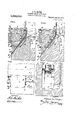
- Figure 1- is a diagrammatic view invertical section of the apparatus, a tank for the continuous supply of glass being shown
- Fig. 2 is a diagrammatic elevation of the same, the glass container being in section.
- Fig. 3 is a vertical section of one side of thecontainer with one of the reinforcing guide devices applied thereto, the bait and the reinforcement for one edge of the sheet being shown in position for starting the. drawing operation
- FIG. 4 is a similar View, illustrating a portion of the sheet and one of. its
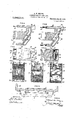
- FIG. 5 1s a view in top plan of the portion of the apparatus shown in Figs. 3 and 4, the sheet and its reinforcement being as illustrated in Fig. Fig. 6 is a vertical section of the contalner from which the sheet is drawn, one of. the guide devices being shown in'elevation.
- Fig. 7 is.
- Figs. 8 andtl are vertical sections of the same, taken on lines 8 8 and 9+9, respectively, of Flg. 7.
- Flg. 10 is a sectional plan on line '10-l0, of, Fig. 9.
- Figs. 11 and 12 are elevations of opposite ends of the guide devices, and
- Fig. 1 3 is-a vertical cross-sec tion of the same on the irregular line 1313, of F g. 9.
- Fig. 14 is-a detail of the bait for starting the drawing operation.
- Fig. 15 is a view in top plan, illustrating a modified arrangement of the guide devices.
- the v scous glass may be supplied in any suitable or convenient manner to the containerfrom which the sheet is drawn.
- a 'contlnuous ope'ratlon which is preferred,'Iconstruct the container 2 as an extension of a glass melting tank 3, with a 'condltloning and refining chamber 4 inter:
- valved passage 5 controlling. the flow of glass from the furnace to chamber l, and a like'passage 6 controlling the flow from chamber e'to container 2.
- the ventilation and temperature of chamber '-l may be con trolled in any suitable and well known manner, the same forming no. 'partof the present invention. This arrangement-of apparatus assures a" continuous supply of glass to container 2 at uniform level. 7
- Container 2 is of 'open-top construction, and is preferably of just sulficient width outwardly, from chamber l-to accommodate the devices 7 at its opposite ends for directing the edge reinforcements to the sheet being drawn,
- These devices are of box-like form. being seated or fixed in the endwalls of. the container, partly above and partly below the'level of the glass;
- At the inner end .or side of each device are the projections 8 which are spaced apart vertically at 9 for the upward passage of a glass sheet A, projections 8 being notched to form a guideway 10 for the edge reinforcing strip B. Projections 8 overhang the molten glass within the container, and guideway 10 d1- rects ihe upward passage of the. reinforce.- nient after it has united with the sheet 'being drawn;
- extension or continuation 11 of guideway 10 below projections 8 is open for a distance to the molten glass,-the lower end of the extension 11 being in communication with slot 12 of the box-like'structure 7, said slotcurving outwardly and downwardly as shown behind the innerportion13 of wall ioo or container 2, and being continued at 14 through the outer surface of said wall for passingthe reinforcing strip upwardly 'to part 11 of the guideway where it unites with the edge of the sheet being drawn.
- the box structure 7 may be of cast-iron or any other suitable material and to preserve. it from the destructive action of the heat it is cored for circulating water around the exposed walls; Referring to this feature of the construction, opposite sides of the top portion of the structure are formed with passages 15 to which water inlets 16 are connected, these passages uniting with cavities 17 in the overhanging extensions 8, while on opposite sides of the reinforcement slot or passageway 12 the structure is made hollowas shown at 18 and 19, cavities 19 extending outwardly around opposite sides of slot 12 with the outlet pipes 20 connected thereto.
- the inner or front surface of the structure is protected by the formation of wall 13, port-ions 21 of the latter extending upwardly on opposite sides of the depression 22, the bottom of the latter being rounded outwardly at 23 in ledge-form where it merges with portion 11 of the reinforcement gu'ideway.
- the box structure 7 may be fixed in the container wall in any suitable manner, in the present adaptation being shown with *a pro ecting port-ion24, recessed to receivea key 25.
- 'lhe'reinforcement B maybe of any suitable material that will unite with the sheet being drawn in such way as to cause the latter to maintain the desired width.
- Strips-of glass are well suited for the purpose as they are adapted to bend under the action of the heat when being drawn upwardly through the guide devices as hereinafter described, also the viscous glass of the sheet forms a welding union with the strips so that the reinforcement and the sheet comprise practically an integral structure throughout the drawing operation.
- the present invention is directed primarily to reinforcing the sheet as it forms,
- apparatustl'iat may be used to advantage, showing therein portions of a building structure provided with three floors C, D, and E, through which the sheet is drawn upwardly, a series of rollers F being illustrated diagrammatically above the intermediate fioor D for moving the sheet progressively at the required speed.
- a series of rollers F being illustrated diagrammatically above the intermediate fioor D for moving the sheet progressively at the required speed.
- Above the lowermost floor G are the opposite gas-burning annealing devices G- between which the sheet is drawn, and above and 2 l have '1' r;
- a bait J of plate-like form is lowered in container 2, as shown in Fig-3, its lower edge being then slightly above the level K of the glass.
- the bait After the bait has become heated sufliciently to make a welding union with the rein for-cement strip-'B, the latter is projected upwardlythrough slot 14; and into slot 12, the extremity thereof softening sufficiently under the heat of the container and the bait to bend'as shown in Fig. 3 and to form a weldingunion with the edge of the bait.
- the level of the glass is raised to the line L, Figs. 3 and t, submerging the lower edge of the baitand the upper extremities of, the reinforcing strips united to its opposite ends.
- the bait is thendrawn upward by any suitable means, thus starting the formation of the glass sheet A, which as it forms unites at its edges with the reinforcements B which.
- the reinforcing strips may be supplied in any desired length, being fed upwardly through slots 14 from theexterior of the container 2, each succeeding section of the reinforcement adhering to the extremity of the last preceding section under the influence of the heat of the container and glass, the reinforcements being thus rendered continuous orunbroken so long as the sheetdrawing operation proceeds.
- the vertical guideway-s 10 through the upper portion of the box-like structure give 7 proper upward direction to the edge'reinforcements, insuring a sheet ,of uniform] width and thickness, there belng no tendency to narrow into string form such as is ordinarily experienced in attempting to draw or" separate a portion of a viscous substance from a mass thereof.
- the arrangement is' preferably such that the sheet A unites with the reinforcement B, midway between the edges of the'latter, as clearly shown in Fig.
- the apparatus may be so disposed as to position the reinforcements at right angles to the'sheet, asin Fig.
- the guideways of the box-like structure 7 may be disposed obliquely to the wall of refining chamber 4 in such manner as to more fully expose them to the heat of said chamber and tothe glass as it passes from the latter into the container 2, as illustrated in Fig. 15.
- the bait J is moved upwardly by means of suitable elevating line and'rollers F, after which the reinforced edges maybe severed by any suitable cutting devices, such as H.
- the sheet may then be cut into sections of any required length.
- I claim 2- A method of producing sheet glass consisting in drawing a sheet from a bath of molten glass, and drawin therewith a previously formed glass reinforcement to which the drawn glass adheres.
- a method of producing sheet-glass consisting in drawing a sheet from a'bath of molten glass, and reinforcing the edges of the sheet when drawing the samewith previously formed pieces of glass.
- a method of producing sheet-glass consisting in drawing a sheet from a bath of molten glass, and drawing and uniting therewith previously formed glass reinforcements.
- a method of producing sheet-glass consisting in drawing a sheet from abath of. molten glass,.and presenting glass reinforcements to the edges of the sheet as the latter takesform with said edges unitin' with the reinforcements intermedlate the e ges of the latter.
- a method of producing sheet-glass consisting in drawing a sheet from a bath of molten glass, entering upwardly movable reinforcing strips in the bath beneath the surface thereof with only one face of each strip exposed to the molten glass; and presenting said exposed faces to the'edges-of the sheet as the latter form and drawing the strips upwardly with the sheet.
- a method of producing sheet-glass consisting in drawing a sheet from a bath of molten glass entering upwardly movable previously formed glass strips in the bath ,beneath the surface thereof with only one face of each strip exposed to the molten glass and-with the strips uniting with the edges of the sheet as the latter takes form, and drawing the strips upwardly along with the sheet.
Landscapes
- Chemical & Material Sciences (AREA)
- Engineering & Computer Science (AREA)
- Materials Engineering (AREA)
- Organic Chemistry (AREA)
- Joining Of Glass To Other Materials (AREA)
Description
A. M. MAZER.
MANUFACTURE onsm'zm GLASS.
- APPLIOATION rum) uowzz, 1911. 1,069,019. Patented Ju1y'29, 1913.
a sunnws-snnm 1.
wrrNEs'sEs 'INVENTOR A. M. MAZER. v MANUFACTURED? SHEET GLASS. .APPLIOATION nun Nov. 22, 19 11.
Patented July 29, 1913.
a sums-sum 3'.-
4 7 7 INVENTOR I? 0%. @mx 4 4 9.
ALFRED MAZER, or JEANNETTE, PENNSYLVANIA;
MANUFACTURE or SHEET-amiss.
Specification of Letters Patent.
Patented-July 29, 1913 Application filed November 22, 1911. Serial lilo. 661,736.-
To all ii/mm it may concern Be it known. that I, ALFRED MQMAZER,
a resident of Jeannette, in the county of .lVestmoreland'and State of Pennsylvania,
ha'veinvented certain'new and useful Improvements in Manufacture of Sheet-Glass, of'which the following is a, 'speci'ficationI This inventionrelates tothe manufacture of sheet-glass, and particularly to the production of a sheet of uniform width and of .lndeternnnate length, the sheet being drawn continuously from a supply of molten or viscous glass, andsubsequently cut into such lengths or sections as may be necessary for its subequ'ent manipulation.
. One difliculty' attending the drawing of glass is its tendencyto narrow into string form. Expedients more or less successful in practice have-beemdevised for overcoming this trouble, and it is to the elimination thereof. that. the' present invention is clirected. Generally stated, it consists in drawing a sheet, together with previously formed edge"reinforcements to which the-sheet adheres, as by a welding union, the reinforcements being passed. continuously to and uniting withthe drawn sheet or film of viscous glass as it emerges from the bath, the sheet thus reinforced maintaining a uniform width, the reinforced edges being trimmed therefrom following the drawing operation.
The method of procedure, and apparatus of desirable form for practising the same are fully described hereinafter in connection with the accompanying drawings, wherein- Figure 1- is a diagrammatic view invertical section of the apparatus, a tank for the continuous supply of glass being shown, and Fig. 2 is a diagrammatic elevation of the same, the glass container being in section.
Fig. 3 is a vertical section of one side of thecontainer with one of the reinforcing guide devices applied thereto, the bait and the reinforcement for one edge of the sheet being shown in position for starting the. drawing operation, and-Fig. 4 is a similar View, illustrating a portion of the sheet and one of. its
edge reinforcements after the drawing has been started. Fig. 5 1s a view in top plan of the portion of the apparatus shown in Figs. 3 and 4, the sheet and its reinforcement being as illustrated in Fig. Fig. 6 is a vertical section of the contalner from which the sheet is drawn, one of. the guide devices being shown in'elevation. Fig. 7 is.
a top plan of the guide devices. Figs. 8 andtl are vertical sections of the same, taken on lines 8 8 and 9+9, respectively, of Flg. 7. Flg. 10 is a sectional plan on line '10-l0, of, Fig. 9. Figs. 11 and 12 are elevations of opposite ends of the guide devices, and Fig. 1 3 is-a vertical cross-sec tion of the same on the irregular line 1313, of F g. 9. Fig. 14 is-a detail of the bait for starting the drawing operation. Fig. 15 is a view in top plan, illustrating a modified arrangement of the guide devices. The v scous glass may be supplied in any suitable or convenient manner to the containerfrom which the sheet is drawn. To facilitate a 'contlnuous ope'ratlon, which is preferred,'Iconstruct the container 2 as an extension of a glass melting tank 3, with a 'condltloning and refining chamber 4 inter:
posed between the tank and container, a valved passage 5 controlling. the flow of glass from the furnace to chamber l, and a like'passage 6 controlling the flow from chamber e'to container 2. The ventilation and temperature of chamber '-l may be con trolled in any suitable and well known manner, the same forming no. 'partof the present invention. This arrangement-of apparatus assures a" continuous supply of glass to container 2 at uniform level. 7
The extension or continuation 11 of guideway 10 below projections 8 is open for a distance to the molten glass,-the lower end of the extension 11 being in communication with slot 12 of the box-like'structure 7, said slotcurving outwardly and downwardly as shown behind the innerportion13 of wall ioo or container 2, and being continued at 14 through the outer surface of said wall for passingthe reinforcing strip upwardly 'to part 11 of the guideway where it unites with the edge of the sheet being drawn.
The box structure 7 may be of cast-iron or any other suitable material and to preserve. it from the destructive action of the heat it is cored for circulating water around the exposed walls; Referring to this feature of the construction, opposite sides of the top portion of the structure are formed with passages 15 to which water inlets 16 are connected, these passages uniting with cavities 17 in the overhanging extensions 8, while on opposite sides of the reinforcement slot or passageway 12 the structure is made hollowas shown at 18 and 19, cavities 19 extending outwardly around opposite sides of slot 12 with the outlet pipes 20 connected thereto. The inner or front surface of the structure is protected by the formation of wall 13, port-ions 21 of the latter extending upwardly on opposite sides of the depression 22, the bottom of the latter being rounded outwardly at 23 in ledge-form where it merges with portion 11 of the reinforcement gu'ideway. The box structure 7 may be fixed in the container wall in any suitable manner, in the present adaptation being shown with *a pro ecting port-ion24, recessed to receivea key 25.
'lhe'reinforcement B maybe of any suitable material that will unite with the sheet being drawn in such way as to cause the latter to maintain the desired width. Strips-of glass are well suited for the purpose as they are adapted to bend under the action of the heat when being drawn upwardly through the guide devices as hereinafter described, also the viscous glass of the sheet forms a welding union with the strips so that the reinforcement and the sheet comprise practically an integral structure throughout the drawing operation.
The present invention is directed primarily to reinforcing the sheet as it forms,
as hereinbefore described, so that the mechanism for effecting the drawing operation is of secondary importance, several forms of apparatus for performing this work and for operating on the sheet after it has been drawn from the molten bath being well known in the art. In
- illustrated diagrammatically apparatustl'iat may be used to advantage, showing therein portions of a building structure provided with three floors C, D, and E, through which the sheet is drawn upwardly, a series of rollers F being illustrated diagrammatically above the intermediate fioor D for moving the sheet progressively at the required speed. Above the lowermost floor G are the opposite gas-burning annealing devices G- between which the sheet is drawn, and above and 2 l have '1' r;
the uppermost floor E are suitable cutters H for trimming ofi the reinforced edges. \Vhile drawing apparatus may be advantageously arranged as thus described, it will be understood that the same may be variously designed without departing from the spirit of the invention.
In starting the drawing operation a bait J of plate-like form is lowered in container 2, as shown in Fig-3, its lower edge being then slightly above the level K of the glass. After the bait has become heated sufliciently to make a welding union with the rein for-cement strip-'B, the latter is projected upwardlythrough slot 14; and into slot 12, the extremity thereof softening sufficiently under the heat of the container and the bait to bend'as shown in Fig. 3 and to form a weldingunion with the edge of the bait. This having been accomplished, the level of the glass is raised to the line L, Figs. 3 and t, submerging the lower edge of the baitand the upper extremities of, the reinforcing strips united to its opposite ends. The bait is thendrawn upward by any suitable means, thus starting the formation of the glass sheet A, which as it forms unites at its edges with the reinforcements B which.
are drawn upward initially, by the bait and which continue'to be drawn upward by the sheet as long as the latter forms.
The reinforcing strips may be supplied in any desired length, being fed upwardly through slots 14 from theexterior of the container 2, each succeeding section of the reinforcement adhering to the extremity of the last preceding section under the influence of the heat of the container and glass, the reinforcements being thus rendered continuous orunbroken so long as the sheetdrawing operation proceeds.
The vertical guideway-s 10 through the upper portion of the box-like structure give 7 proper upward direction to the edge'reinforcements, insuring a sheet ,of uniform] width and thickness, there belng no tendency to narrow into string form such as is ordinarily experienced in attempting to draw or" separate a portion of a viscous substance from a mass thereof. -The arrangementis' preferably such that the sheet A unites with the reinforcement B, midway between the edges of the'latter, as clearly shown in Fig. The apparatus may be so disposed as to position the reinforcements at right angles to the'sheet, asin Fig. 5, or the guideways of the box-like structure 7 may be disposed obliquely to the wall of refining chamber 4 in such manner as to more fully expose them to the heat of said chamber and tothe glass as it passes from the latter into the container 2, as illustrated in Fig. 15.
When starting the drawing operation as above described, the bait J is moved upwardly by means of suitable elevating line and'rollers F, after which the reinforced edges maybe severed by any suitable cutting devices, such as H. The sheet may then be cut into sections of any required length.
While I have illustrated desirable means for presentingthe reinforcements to the edges vof the drawn sheet, I do not limit myself thereto as the underlying method may be practised by various means without departing from the invention.
I claim 2- 1. A method of producing sheet glass consisting in drawing a sheet from a bath of molten glass, and drawin therewith a previously formed glass reinforcement to which the drawn glass adheres.
2. A method of producing sheet-glass consisting in drawing a sheet from a'bath of molten glass, and reinforcing the edges of the sheet when drawing the samewith previously formed pieces of glass.
3. A method of producing sheet-glass consisting in drawing a sheet from a bath of molten glass, and drawing and uniting therewith previously formed glass reinforcements. v
4. A method of producing sheet-glass consisting in drawing a sheet from abath of. molten glass,.and presenting glass reinforcements to the edges of the sheet as the latter takesform with said edges unitin' with the reinforcements intermedlate the e ges of the latter. v
5. A method of producing sheet-glass consisting in drawing a sheet from a bath of molten glass, entering upwardly movable reinforcing strips in the bath beneath the surface thereof with only one face of each strip exposed to the molten glass; and presenting said exposed faces to the'edges-of the sheet as the latter form and drawing the strips upwardly with the sheet.
6. A method of producing sheet-glass consisting in drawing a sheet from a bath of molten glass entering upwardly movable previously formed glass strips in the bath ,beneath the surface thereof with only one face of each strip exposed to the molten glass and-with the strips uniting with the edges of the sheet as the latter takes form, and drawing the strips upwardly along with the sheet. In testimony whereof I afiix my signature in presence of two witnesses.
ALFRED M. MAZER.
WVitnesses:
J. M. NEsBrr, F. E. GAITHER.
Priority Applications (1)
| Application Number | Priority Date | Filing Date | Title |
|---|---|---|---|
| US66173611A US1069019A (en) | 1911-11-22 | 1911-11-22 | Manufacture of sheet-glass. |
Applications Claiming Priority (1)
| Application Number | Priority Date | Filing Date | Title |
|---|---|---|---|
| US66173611A US1069019A (en) | 1911-11-22 | 1911-11-22 | Manufacture of sheet-glass. |
Publications (1)
| Publication Number | Publication Date |
|---|---|
| US1069019A true US1069019A (en) | 1913-07-29 |
Family
ID=3137257
Family Applications (1)
| Application Number | Title | Priority Date | Filing Date |
|---|---|---|---|
| US66173611A Expired - Lifetime US1069019A (en) | 1911-11-22 | 1911-11-22 | Manufacture of sheet-glass. |
Country Status (1)
| Country | Link |
|---|---|
| US (1) | US1069019A (en) |
-
1911
- 1911-11-22 US US66173611A patent/US1069019A/en not_active Expired - Lifetime
Similar Documents
| Publication | Publication Date | Title |
|---|---|---|
| US4525194A (en) | Apparatus for simultaneous production of double glass panels | |
| US1940975A (en) | Apparatus for producing mineral wool | |
| US1578250A (en) | Process of making plaster board | |
| US1986575A (en) | Apparatus for and method of delivering molten glass | |
| US1069019A (en) | Manufacture of sheet-glass. | |
| US2044234A (en) | Method of manufacturing wallboard | |
| US2067312A (en) | Process of treating slag | |
| US2257112A (en) | Manufacture of special shapes of heat and sound insulation bodies | |
| US3689192A (en) | Manufacture of film from thermoplastic material that is blown by a blowhead | |
| US1734965A (en) | Method and apparatus for forming glassware | |
| US2226498A (en) | Glass melting and delivering apparatus and method | |
| US1476796A (en) | Machine for forming tubes | |
| US2119495A (en) | Form for making rubber articles | |
| US1597440A (en) | Continuous tank furnace | |
| US2015681A (en) | Method of and apparatus for making hollow ceramic ware | |
| US1248809A (en) | Method and apparatus for making sheet-glass. | |
| US1810920A (en) | Sheet glass apparatus | |
| US1179251A (en) | Drawing-ring. | |
| US846102A (en) | Method and apparatus for drawing glass. | |
| US1597953A (en) | Manufacture of sheet and wire glass | |
| US1161913A (en) | Manufacture of glass sheets. | |
| US1670247A (en) | Plurality-sheet-drawing apparatus | |
| US1841715A (en) | Sheet glass apparatus | |
| US1961494A (en) | Sheet glass apparatus | |
| US1618107A (en) | Drawing sheet glass |