US10690094B2 - Intake apparatus - Google Patents
Intake apparatus Download PDFInfo
- Publication number
- US10690094B2 US10690094B2 US16/035,966 US201816035966A US10690094B2 US 10690094 B2 US10690094 B2 US 10690094B2 US 201816035966 A US201816035966 A US 201816035966A US 10690094 B2 US10690094 B2 US 10690094B2
- Authority
- US
- United States
- Prior art keywords
- gas
- intake
- hot water
- intake manifold
- egr
- Prior art date
- Legal status (The legal status is an assumption and is not a legal conclusion. Google has not performed a legal analysis and makes no representation as to the accuracy of the status listed.)
- Active, expires
Links
Images


Classifications
-
- F—MECHANICAL ENGINEERING; LIGHTING; HEATING; WEAPONS; BLASTING
- F02—COMBUSTION ENGINES; HOT-GAS OR COMBUSTION-PRODUCT ENGINE PLANTS
- F02M—SUPPLYING COMBUSTION ENGINES IN GENERAL WITH COMBUSTIBLE MIXTURES OR CONSTITUENTS THEREOF
- F02M26/00—Engine-pertinent apparatus for adding exhaust gases to combustion-air, main fuel or fuel-air mixture, e.g. by exhaust gas recirculation [EGR] systems
- F02M26/13—Arrangement or layout of EGR passages, e.g. in relation to specific engine parts or for incorporation of accessories
- F02M26/17—Arrangement or layout of EGR passages, e.g. in relation to specific engine parts or for incorporation of accessories in relation to the intake system
- F02M26/18—Thermal insulation or heat protection
-
- F—MECHANICAL ENGINEERING; LIGHTING; HEATING; WEAPONS; BLASTING
- F02—COMBUSTION ENGINES; HOT-GAS OR COMBUSTION-PRODUCT ENGINE PLANTS
- F02M—SUPPLYING COMBUSTION ENGINES IN GENERAL WITH COMBUSTIBLE MIXTURES OR CONSTITUENTS THEREOF
- F02M35/00—Combustion-air cleaners, air intakes, intake silencers, or induction systems specially adapted for, or arranged on, internal-combustion engines
- F02M35/10—Air intakes; Induction systems
- F02M35/10209—Fluid connections to the air intake system; their arrangement of pipes, valves or the like
- F02M35/10222—Exhaust gas recirculation [EGR]; Positive crankcase ventilation [PCV]; Additional air admission, lubricant or fuel vapour admission
-
- F—MECHANICAL ENGINEERING; LIGHTING; HEATING; WEAPONS; BLASTING
- F02—COMBUSTION ENGINES; HOT-GAS OR COMBUSTION-PRODUCT ENGINE PLANTS
- F02M—SUPPLYING COMBUSTION ENGINES IN GENERAL WITH COMBUSTIBLE MIXTURES OR CONSTITUENTS THEREOF
- F02M26/00—Engine-pertinent apparatus for adding exhaust gases to combustion-air, main fuel or fuel-air mixture, e.g. by exhaust gas recirculation [EGR] systems
- F02M26/13—Arrangement or layout of EGR passages, e.g. in relation to specific engine parts or for incorporation of accessories
- F02M26/17—Arrangement or layout of EGR passages, e.g. in relation to specific engine parts or for incorporation of accessories in relation to the intake system
- F02M26/20—Feeding recirculated exhaust gases directly into the combustion chambers or into the intake runners
-
- F—MECHANICAL ENGINEERING; LIGHTING; HEATING; WEAPONS; BLASTING
- F02—COMBUSTION ENGINES; HOT-GAS OR COMBUSTION-PRODUCT ENGINE PLANTS
- F02M—SUPPLYING COMBUSTION ENGINES IN GENERAL WITH COMBUSTIBLE MIXTURES OR CONSTITUENTS THEREOF
- F02M26/00—Engine-pertinent apparatus for adding exhaust gases to combustion-air, main fuel or fuel-air mixture, e.g. by exhaust gas recirculation [EGR] systems
- F02M26/13—Arrangement or layout of EGR passages, e.g. in relation to specific engine parts or for incorporation of accessories
- F02M26/22—Arrangement or layout of EGR passages, e.g. in relation to specific engine parts or for incorporation of accessories with coolers in the recirculation passage
- F02M26/23—Layout, e.g. schematics
- F02M26/28—Layout, e.g. schematics with liquid-cooled heat exchangers
-
- F—MECHANICAL ENGINEERING; LIGHTING; HEATING; WEAPONS; BLASTING
- F02—COMBUSTION ENGINES; HOT-GAS OR COMBUSTION-PRODUCT ENGINE PLANTS
- F02M—SUPPLYING COMBUSTION ENGINES IN GENERAL WITH COMBUSTIBLE MIXTURES OR CONSTITUENTS THEREOF
- F02M26/00—Engine-pertinent apparatus for adding exhaust gases to combustion-air, main fuel or fuel-air mixture, e.g. by exhaust gas recirculation [EGR] systems
- F02M26/13—Arrangement or layout of EGR passages, e.g. in relation to specific engine parts or for incorporation of accessories
- F02M26/22—Arrangement or layout of EGR passages, e.g. in relation to specific engine parts or for incorporation of accessories with coolers in the recirculation passage
- F02M26/29—Constructional details of the coolers, e.g. pipes, plates, ribs, insulation or materials
- F02M26/30—Connections of coolers to other devices, e.g. to valves, heaters, compressors or filters; Coolers characterised by their location on the engine
-
- F—MECHANICAL ENGINEERING; LIGHTING; HEATING; WEAPONS; BLASTING
- F02—COMBUSTION ENGINES; HOT-GAS OR COMBUSTION-PRODUCT ENGINE PLANTS
- F02M—SUPPLYING COMBUSTION ENGINES IN GENERAL WITH COMBUSTIBLE MIXTURES OR CONSTITUENTS THEREOF
- F02M35/00—Combustion-air cleaners, air intakes, intake silencers, or induction systems specially adapted for, or arranged on, internal-combustion engines
- F02M35/10—Air intakes; Induction systems
- F02M35/10006—Air intakes; Induction systems characterised by the position of elements of the air intake system in direction of the air intake flow, i.e. between ambient air inlet and supply to the combustion chamber
- F02M35/10026—Plenum chambers
- F02M35/10052—Plenum chambers special shapes or arrangements of plenum chambers; Constructional details
-
- F—MECHANICAL ENGINEERING; LIGHTING; HEATING; WEAPONS; BLASTING
- F02—COMBUSTION ENGINES; HOT-GAS OR COMBUSTION-PRODUCT ENGINE PLANTS
- F02M—SUPPLYING COMBUSTION ENGINES IN GENERAL WITH COMBUSTIBLE MIXTURES OR CONSTITUENTS THEREOF
- F02M35/00—Combustion-air cleaners, air intakes, intake silencers, or induction systems specially adapted for, or arranged on, internal-combustion engines
- F02M35/10—Air intakes; Induction systems
- F02M35/10091—Air intakes; Induction systems characterised by details of intake ducts: shapes; connections; arrangements
- F02M35/10144—Connections of intake ducts to each other or to another device
-
- F—MECHANICAL ENGINEERING; LIGHTING; HEATING; WEAPONS; BLASTING
- F02—COMBUSTION ENGINES; HOT-GAS OR COMBUSTION-PRODUCT ENGINE PLANTS
- F02M—SUPPLYING COMBUSTION ENGINES IN GENERAL WITH COMBUSTIBLE MIXTURES OR CONSTITUENTS THEREOF
- F02M35/00—Combustion-air cleaners, air intakes, intake silencers, or induction systems specially adapted for, or arranged on, internal-combustion engines
- F02M35/10—Air intakes; Induction systems
- F02M35/10242—Devices or means connected to or integrated into air intakes; Air intakes combined with other engine or vehicle parts
- F02M35/10268—Heating, cooling or thermal insulating means
-
- F—MECHANICAL ENGINEERING; LIGHTING; HEATING; WEAPONS; BLASTING
- F02—COMBUSTION ENGINES; HOT-GAS OR COMBUSTION-PRODUCT ENGINE PLANTS
- F02M—SUPPLYING COMBUSTION ENGINES IN GENERAL WITH COMBUSTIBLE MIXTURES OR CONSTITUENTS THEREOF
- F02M35/00—Combustion-air cleaners, air intakes, intake silencers, or induction systems specially adapted for, or arranged on, internal-combustion engines
- F02M35/10—Air intakes; Induction systems
- F02M35/104—Intake manifolds
-
- F—MECHANICAL ENGINEERING; LIGHTING; HEATING; WEAPONS; BLASTING
- F02—COMBUSTION ENGINES; HOT-GAS OR COMBUSTION-PRODUCT ENGINE PLANTS
- F02M—SUPPLYING COMBUSTION ENGINES IN GENERAL WITH COMBUSTIBLE MIXTURES OR CONSTITUENTS THEREOF
- F02M26/00—Engine-pertinent apparatus for adding exhaust gases to combustion-air, main fuel or fuel-air mixture, e.g. by exhaust gas recirculation [EGR] systems
- F02M26/02—EGR systems specially adapted for supercharged engines
- F02M26/04—EGR systems specially adapted for supercharged engines with a single turbocharger
- F02M26/06—Low pressure loops, i.e. wherein recirculated exhaust gas is taken out from the exhaust downstream of the turbocharger turbine and reintroduced into the intake system upstream of the compressor
Definitions
- the present disclosure relates to an intake apparatus provided with: an intake manifold including a plurality of branch pipes; and a gas distributor for distributing auxiliary gas, such as EGR gas and PCV gas, to each of the branch pipes.
- auxiliary gas such as EGR gas and PCV gas
- JP 2005-155448A discloses an intake manifold disclosed in Japanese unexamined patent application publication No. 2005-155448 (JP 2005-155448A).
- This intake manifold is provided with a plurality of intake pipes (branch pipes) each configured to distribute intake air to one of cylinders and an EGR gas chamber (a gas distributor) configured to distribute EGR gas to each of the intake pipes.
- the EGR gas chamber is provided on an upper side of the intake pipes and in an orientation traversing and straddling each intake pipe.
- the EGR gas chamber is formed integrally with the intake manifold.
- the EGR gas chamber is constituted of a chamber body formed integrally with an upper wall of the intake manifold and a cover body that covers an opening formed on an upper surface side of the chamber body.
- the chamber body is also formed, in its bottom wall, with an EGR gas inflow port.
- the intake manifold is formed with an EGR gas passage communicated with the EGR gas inflow port.
- the chamber body is further formed with communication holes each communicated with one of the intake pipes.
- the cover body is formed, in its inside, with a recess for allowing EGR gas to stay therein. On the outside of the recess, a hot water passage is provided adjacent to the recess to allow engine cooling water (hot water) to flow.
- part of the EGR gas having flowed in the EGR gas chamber through the EGR gas inflow port can stay in the recess.
- the above intake manifold is made as a rein molded component even though not specified.
- the EGR gas chamber is constituted of: the chamber body formed integrally with the intake manifold; and the cover body covering the chamber body, the chamber body is assumed to be made of resin by molding integrally with the intake manifold.
- the rein molded component has a limitation in shape in terms of a demolding work.
- Such an EGR gas chamber formed integrally with the intake manifold could lack general versatility for different types of intake manifolds.
- each communication hole provided in the chamber body simply communicates with each corresponding intake pipe and thus a leakage flow of the condensed water from each communication hole to each intake pipe may flow down to an upstream side of each intake pipe depending on the placement of the communication holes. Since a surge tank is usually provided on the upstream side of the intake pipes, the condensed water may be accumulated in the surge tank.
- This disclosure has been made to address the above problems and has a purpose to provide an intake apparatus provided with a gas distributor for distributing auxiliary gas, such as EGR gas, to each branch pipe of an intake manifold and configured to suppress the generation of condensed water in the gas distributor and further realize the general versatility of the gas distributor to different types of intake manifolds.
- auxiliary gas such as EGR gas
- an intake apparatus comprising: an intake manifold including a surge tank and a plurality of branch pipes each branching off from the surge tank; a gas distributor provided separately from the intake manifold and configured to distribute auxiliary gas to each of the plurality of branch pipes, the gas distributor including a gas inlet configured to introduce the auxiliary gas, a gas chamber configured to collect the auxiliary gas introduced through the gas inlet, and a plurality of gas distribution pipes each branching off from the gas chamber and each configured to connect to one of the branch pipes; a plurality of connecting holes each provided in one of the branch pipes and each configured to connect to a corresponding one of the gas distribution pipes; and a hot water passage provided separately from the intake manifold and placed adjacently to the gas chamber to warm an inside wall of the gas chamber, the hot water passage being configured to flow hot water, wherein the gas chamber and the hot water passage are arranged to traverse the plurality of branch pipes, the gas distribution pipes are each connected to one of the connecting holes
- an inside wall of a gas chamber of a gas distributor can be efficiently warmed with hot water in the gas chamber, thus enabling prevention of generation and freezing of condensed water on the inside wall of the gas chamber. Furthermore, standardization of the gas distributor and a hot water passage can lead to general versatility for different types of intake manifolds.
- FIG. 1 is a perspective view of an intake apparatus viewed from a front side in an embodiment
- FIG. 2 is a perspective view of the intake apparatus viewed from a back side in the embodiment
- FIG. 3 is a front view of the intake apparatus in the embodiment
- FIG. 4 is a back view of the intake apparatus in the embodiment
- FIG. 5 is a plane view of the intake apparatus in the embodiment.
- FIG. 6 is a bottom view of the intake apparatus in the embodiment.
- FIG. 7 is a right-side view of the intake apparatus in the embodiment.
- FIG. 8 is a left-side view of the intake apparatus in the embodiment.
- FIG. 9 is a cross-sectional view of the intake apparatus taken along a line A-A in FIG. 5 in the embodiment.
- FIG. 10 is a cross-sectional view of the intake apparatus taken along a line B-B in FIG. 5 in the embodiment;
- FIG. 11 is a cross-sectional view of the intake apparatus taken along a line C-C in FIG. 5 in the embodiment;
- FIG. 12 is a cross-sectional view of the intake apparatus taken along a line D-D in FIG. 8 in the embodiment;
- FIG. 13 is a cross-sectional view of the intake apparatus attached to an engine mounted in a proper position in the embodiment
- FIG. 14 is a cross-sectional view of an intake apparatus in another embodiment, corresponding to FIG. 10 ;
- FIG. 15 is a cross-sectional view of an intake apparatus in still another embodiment, corresponding to FIG. 10 .
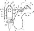
- FIG. 1 is a perspective view of an intake apparatus 1 viewed from a front side.
- FIG. 2 is a perspective view of the intake apparatus 1 viewed from a back side.
- FIG. 3 is a front view of the intake apparatus 1 .
- FIG. 4 is a back view of the intake apparatus 1 .
- FIG. 5 is a plane view of the intake apparatus 1 .
- FIG. 6 is a bottom view of the intake apparatus 1 .
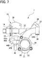
- FIG. 7 is a right-side view of the intake apparatus 1 .
- FIG. 8 is a left-side view of the intake apparatus 1 .
- FIG. 9 is a cross-sectional view of the intake apparatus 1 taken along a line A-A in FIG. 5 .
- FIG. 10 is a cross-sectional view of the intake apparatus 1 taken along a line B-B in FIG. 5 .
- FIG. 11 is a cross-sectional view of the intake apparatus 1 taken along a line C-C in FIG. 5 .
- FIG. 12 is a cross-sectional view of the intake apparatus 1 taken along a line D-D in FIG. 8 .
- FIG. 13 is a cross-sectional view of the intake apparatus 1 attached to an engine 2 mounted in a proper position.
- the upper and lower sides and right and left sides of the intake apparatus 1 are specified as shown in FIGS. 3 and 4 or FIGS. 7 and 8 .
- a state of the intake apparatus 1 actually attached to the engine 2 is as illustrated in FIG. 13 .
- This intake apparatus 1 is used in the attached state to the engine 2 to introduce intake air and EGR gas as auxiliary gas to a plurality of cylinders of the engine 2 .
- the intake apparatus 1 is provided with an intake manifold 11 and an EGR unit 15 .
- This EGR unit 15 includes an EGR gas distributor 12 , an EGR cooler 13 , and an EGR valve 14 .
- the EGR gas distributor 12 corresponds to one example of a gas distributor in the present disclosure.
- the EGR cooler 13 corresponds to one example of an auxiliary gas cooler in the present disclosure, in which a hot water passage (also serving as a cooling water passage) 36 (see FIG. 12 and others and a gas passage 37 (see FIGS. 12 and others) are internally contained.
- the EGR valve 14 is configured to be electrically controlled to regulate a flow rate of EGR gas allowed to flow from the EGR cooler 13 into the EGR gas distributor 12 .
- the intake manifold 11 includes a surge tank 21 and a plurality of branch pipes 22 A, 22 B, and 22 C each branching off from the surge tank 21 .
- the branch pipes 22 A to 22 C are formed to curve in parallel to each other from the surge tank 21 and extend in the same direction.
- the intake manifold 11 includes three branch pipes 22 A to 22 C for a 3-cylinder engine 2 .
- the surge tank 21 is formed with an intake inlet 23 to introduce intake air into the surge tank 21 .
- An inlet flange 24 surrounds the outer circumference of the intake inlet 23 .
- the inlet flange 24 is adapted to allow attachment of a well-known throttle device.
- an intake outlet 25 is provided to introduce intake air toward each intake port 3 (see FIG. 13 ) of the engine 2 .
- An outlet flange 26 surrounds the outer circumference of each intake outlet 25 .
- This outlet flange 26 is formed with a plurality of bolt holes 26 a to receive bolts or the like for attachment of the intake manifold 11 to the engine 2 .
- the EGR gas distributor 12 is made of a resin material as a separate component from the intake manifold 11 and is retrofitted to the intake manifold 11 .
- this distributor 12 is made of a resin material containing carbon.
- the EGR gas distributor 12 serves to distribute EGR gas to each of the branch pipes 22 A to 22 C. As shown in FIG.
- the EGR gas distributor 12 includes a gas inlet 29 configured to introduce EGR gas, a gas chamber 30 configured to collect the EGR gas introduced therein through the gas inlet 29 , and a plurality of gas distribution pipes 31 A, 31 B, and 31 C each branching off from the gas chamber 30 and configured to respectively communicate with the branch pipes 22 A, 22 B, and 22 C.
- the EGR cooler 13 internally contains the hot water passage 36 and the gas passage 37 and is formed integrally with the EGR gas distributor 12 .
- the EGR cooler 13 is formed integrally with the EGR gas distributor 12 but is formed separately from the intake manifold 11 .
- the EGR cooler 13 is provided adjacently to and integrally with the EGR gas distributor 12 to warm the inside wall of this distributor 12 .
- the EGR cooler 13 is provided with a casing 38 made of a resin material in an integral form with the EGR gas distributor 12 . Within this casing 38 , there are placed the hot water passage 36 to flow engine cooling water (hot water) and the gas passage 37 to flow EGR gas.
- a cooler flange 39 is provided at one end of the EGR cooler 13 .
- This cooler flange 39 is provided with a gas introduction part 40 configured to introduce EGR gas, a water inflow pipe joint 41 configured to introduce engine cooling water, and a water outflow pipe joint 42 configured to discharge out the engine cooling water. Further, at the other end of the EGR cooler 13 , a communication passage 43 is provided to connect the gas passage 37 to the gas inlet 29 of the EGR gas distributor 12 . The EGR valve 14 is placed in this communication passage 43 .
- the EGR cooler 13 further includes two brackets 44 A and 44 B configured to attach the EGR unit 15 to the intake manifold 1 .
- the branch pipes 22 A to 22 C of the intake manifold 11 are each provided with a connecting hole 46 configured to connect to a corresponding one of gas distribution pipes 31 A to 31 C of the EGR gas distributor 12 .
- the connecting holes 46 are open near and toward the corresponding intake outlets 25 .
- the intake manifold 11 includes two connecting rods 47 A and 47 B protruded and connected respectively to the brackets 44 A and 44 B of the EGR cooler 13 .
- the EGR gas distributor 12 and the EGR cooler 13 are placed in parallel to each other in a longitudinal direction.
- the gas chamber 30 of the EGR gas distributor 12 and the hot water passage 36 of the EGR cooler 13 are arranged adjacent to each other through a partition wall 38 a in the longitudinal direction.
- the gas chamber 30 of the EGR gas distributor 12 has a cross section of a nearly triangular shape so that a portion of the gas chamber 30 defined by one side of the triangular shape is formed by the partition wall 38 a extending in the longitudinal direction.
- the gas chamber 30 of the EGR gas distributor 12 and the hot water passage 36 of the EGR cooler 13 are arranged in an orientation extending in the longitudinal direction so as to traverse the plurality of branch pipes 22 A to 22 C.
- the gas distribution pipes 31 A to 31 C are each connected to the corresponding connecting holes 46 .
- the two brackets 44 A and 44 B of the EGR cooler 13 are connected respectively to the two connecting rods 47 A and 47 B of the intake manifold 11 . In this manner, the EGR unit 15 is attached to the intake manifold 11 .
- the intake manifold 11 is installed in an orientation inclined downward at a predetermined angle ⁇ 1 with respect to a horizontal direction PL onto the engine 2 mounted in a proper position (i.e., an actually installed position of the engine 2 in a vehicle).
- a pipe section 48 defined by a part of each of the branch pipes 22 A to 22 C, in which the connecting holes 46 and the intake outlets 25 are provided is placed to be directed, or inclined, downward relative to the horizontal direction PL. Accordingly, outlets of the gas distribution pipes 31 A to 31 C connected to the connecting holes 46 are also directed toward the corresponding intake outlets 25 and downward relative to the horizontal direction PL.
- the gas chamber 30 of the EGR gas distributor 12 includes a bottom wall 38 b in an orientation extending in the longitudinal direction so as to traverse the plurality of branch pipes 22 A to 22 C.
- the bottom wall 38 b is directed, or inclined, downward relative to the horizontal direction PL as shown in FIG. 13 .
- the bottom wall 38 b and the gas distribution pipes 31 A to 31 C are each inclined downward relative to the horizontal direction PL.
- the intake manifold 11 is first installed onto the engine 2 before the intake apparatus 1 is attached to the engine 2 .
- the outlet flange 26 of the intake manifold 11 is secured with bolts tightened to the engine 2 in a position corresponding to the plurality of intake ports 3 of the engine 2 .
- the EGR unit 15 does not exist near the outlet flange 26 and therefore the EGR unit 15 itself does not interfere with a work of tightening the bolts.
- the EGR unit 15 is attached to the intake manifold 11 .
- This attaching procedure is conducted as follows. Firstly, the gas distribution pipes 31 A to 31 C of the EGR gas distributor 12 are connected by press-fitting into the corresponding connecting holes 46 .
- brackets 44 A and 44 B are connected respectively to the connecting rods 47 A and 47 B.
- This connecting method may be performed by bonding or welding the brackets 44 A and 44 B to the connecting rods 47 A and 47 B or by securing them with bolts or the like.
- the hot water passage 36 is provided adjacently to the gas chamber 30 of the EGR gas distributor 12 , so that the heat of hot water flowing through the hot water passage 36 transfers to the inside wall of the gas chamber 30 , thereby warming this inside wall. Accordingly, the inside wall of the gas chamber 30 of the EGR gas distributor 12 can be efficiently warmed by the hot water, thus enabling preventing condensed water from being generated and frozen on the inside wall of the gas chamber 30 .
- the gas chamber 30 and the hot water passage 36 are placed so as to traverse or extend across the plurality of branch pipes 22 A to 22 C, the gas distribution pipes 31 A to 31 C are connected to the corresponding connecting holes 46 , and also the EGR gas distributor 12 and the EGR cooler 13 are attached to the intake manifold 11 . Therefore, when the EGR unit 15 provided with the EGR gas distributor 12 and the EGR cooler 13 is standardized, this EGR unit 15 can also be used in any other type intake manifold. Thus, by standardizing the EGR gas distributor 12 and the EGR cooler 13 (including the hot water passage 36 ), general versatility for different types of intake manifolds can be achieved.
- the partition wall 38 a interposed between the gas chamber 30 and the hot water passage 36 is made of a resin material containing carbon.
- This configuration exhibits high heat transfer, so that the heat of the hot water can be easily transferred to the inside wall of the gas chamber 30 .
- the inside wall of the gas chamber 30 can be more efficiently warmed by the hot water.
- a portion of the gas chamber 30 having a nearly triangular cross-sectional shape forms a rectangular partition wall 38 a extending in the longitudinal direction.
- a heat transfer area between the gas chamber 30 and the hot water passage 36 is relatively large, resulting in an increase in quantity of heat to be transferred to the inside of the gas chamber 30 .
- the inside wall of the gas chamber 30 can be more efficiently warmed by the hot water.
- the pipe section 48 defined by a part of each of the branch pipes 22 A to 22 C in which the connecting holes 46 and the intake outlets 25 are provided is placed to be directed, or inclined, downward relative to the horizontal direction PL.
- the outlets of the gas distribution pipes 31 A to 31 C are also directed toward the intake port 3 of the engine 2 through the intake outlets 25 .
- the intake apparatus 1 configured as above can suppress the generation of condensed water in the EGR gas distributor 12 and, even if the condensed water unexpectedly occurs and flows out of the EGR gas distributor 12 , the intake apparatus 1 can also prevent such the condensed water from staying in the intake manifold 11 .
- the unexpectedly generated condensed water is small in quantity; therefore, even if flowing into the engine 2 , such a condensed water is less likely to lead to any defects, such as combustion deterioration.
- the bottom wall 38 b of the gas chamber 30 of the EGR gas distributor 12 is inclined downward toward the gas distribution pipes 31 A to 31 C.
- the condensed water unexpectedly generated in the gas chamber 30 is allowed to flow downward from the bottom wall 38 b to the gas distribution pipes 31 A to 31 C.
- This configuration can prevent the condensed water generated in the EGR gas distributor 12 from staying in this distributor 12 .
- a small quantity of condensed water unexpectedly generated may flow into the engine 2 .
- such a small quantity of condensed water is less likely to any defects, such as combustion deterioration.
- the hot water passage 36 is formed integrally with the EGR gas distributor 12 , that is, the EGR cooler 13 including the hot water passage 36 is formed integrally with the EGR gas distributor 12 . Standardization of those components thus enables attachment to the intake manifold 11 . This can facilitate a work of attaching the EGR gas distributor 12 and the EGR cooler 13 (including the hot water passage 36 ) to the intake manifold 11 .
- the intake apparatus 1 is configured such that the intake manifold 11 is attached to the engine 2 and then the EGR unit 15 is retrofitted to the intake manifold 11 .
- This configuration can prevent the existence of the EGR unit 15 from interfering with the work of attaching the intake manifold 11 to the engine 2 .
- the EGR cooler 13 internally containing the hot water passage 36 and the gas passage 37 is provided integrally with the EGR gas distributor 12 .
- an additional casing 51 may be provided to surround the gas chamber 30 of the EGR gas distributor 12 so that only the hot water passage 36 is provided integrally with the EGR gas distributor 12 , as shown in FIG. 14 .
- a cooling water passage for supplying engine cooling water to an EGR cooler provided separately from the intake manifold 11 has only to be connected to this hot water passage 36 .
- FIG. 14 shows this modified example of the intake apparatus in a cross-sectional view corresponding to FIG. 10 .
- the EGR cooler 13 internally containing the hot water passage 36 and the gas passage 37 is provided integrally with the EGR gas distributor 12 .
- an additional casing 51 may be provided to surround the EGR gas distributor 12 so that only the hot water passage 36 is provided integrally with the EGR gas distributor 12 as shown in FIG. 15 .
- the intake manifold 11 is attached in a position downwardly inclined at a predetermined angle ⁇ 1 with respect to a horizontal direction PL onto the engine 2 mounted in a proper position.
- a bottom wall 12 a of the EGR gas distributor 12 constituting the gas chamber 30 can be placed to be directed, or inclined, downward relative to the horizontal direction PL and also the bottom wall 12 a can be configured to be linearly continuous with the inside walls of the gas distribution pipes 31 A to 31 C.
- the bottom wall 12 a and each gas distribution pipe 31 A to 31 C can be each arranged to be directed downward relative to the horizontal direction PL.
- a cooling water passage for supplying engine cooling water to an EGR cooler provided separately from the intake manifold 11 is connected to the hot water passage 36 , so that the same operations and effects as in the foregoing embodiment can be achieved.
- the condensed water generated in the gas chamber 30 is allowed to flow toward the engine 2 without staying in the gas chamber 30 .
- FIG. 15 shows this modified example of the intake apparatus in a cross-sectional view corresponding to FIG. 10 .
- the casing 38 integrally constituting the EGR gas distributor 12 and the EGR cooler 13 is entirely made of a resin material containing carbon.
- the partition wall that separates the gas chamber of the EGR gas distributor and the hot water passage of the EGR cooler may be made of a resin material containing carbon.
- the high heat transfer is addressed by the configuration that the partition wall 38 a and others are made of a resin material with carbon mixed therein.
- the partition wall may be made of resin with a metal plate embedded therein by insert molding.
- the EGR gas distributor 12 and the EGR cooler 13 are configured as an integral unit so that the EGR cooler 13 is attached to the intake manifold 11 through the brackets 44 A and 44 B and the connecting rods 47 A and 47 B.
- the EGR gas distributor and the EGR cooler may be configured as an integral unit so that the EGR gas distributor is attached to the intake manifold through a connecting means or so that the EGR gas distributor and the EGR cooler are each connected to the intake manifold through corresponding connecting means.
- the foregoing embodiment embodies the intake manifold 11 provided with the three branch pipes 22 A to 22 C.
- the number of branch pipes may be any values without being limited to three.
- the intake manifold 11 may be constituted of an integral unit formed of a plurality of separate pieces joined into one.
- the EGR valve 14 is provided in the EGR unit 15 ; however, this EGR valve may be omitted.
- EGR gas is adopted as auxiliary gas but PCV gas (blow-by gas) may also be adopted as auxiliary gas.
- the present disclosure is applicable as a component of an intake system in various types of engines.
Landscapes
- Engineering & Computer Science (AREA)
- Chemical & Material Sciences (AREA)
- Combustion & Propulsion (AREA)
- Mechanical Engineering (AREA)
- General Engineering & Computer Science (AREA)
- Physics & Mathematics (AREA)
- Geometry (AREA)
- Exhaust-Gas Circulating Devices (AREA)
Abstract
Description
- 1 Intake apparatus
- 2 Engine
- 3 Intake port
- 11 Intake manifold
- 12 EGR gas distributor (Gas distributor)
- 13 EGR cooler (Auxiliary gas cooler)
- 15 EGR unit
- 21 Surge tank
- 22A Branch pipe
- 22B Branch pipe
- 22C Branch pipe
- 25 Intake outlet
- 29 Gas inlet
- 30 Gas chamber
- 31A Gas distribution pipe
- 31B Gas distribution pipe
- 31C Gas distribution pipe
- 36 Hot water passage
- 37 Gas passage
- 38 Casing
- 38 a Partition wall
- 38 b Bottom wall
- 44A Bracket
- 44B Bracket
- 46 Connection hole
- 47A Connecting rod
- 47B Connecting rod
- 48 Pipe section
- PL Horizontal direction
- θ1 Predetermined angle
Claims (5)
Applications Claiming Priority (2)
| Application Number | Priority Date | Filing Date | Title |
|---|---|---|---|
| JP2017-166507 | 2017-08-31 | ||
| JP2017166507A JP2019044644A (en) | 2017-08-31 | 2017-08-31 | Intake system |
Publications (2)
| Publication Number | Publication Date |
|---|---|
| US20190063381A1 US20190063381A1 (en) | 2019-02-28 |
| US10690094B2 true US10690094B2 (en) | 2020-06-23 |
Family
ID=65435029
Family Applications (1)
| Application Number | Title | Priority Date | Filing Date |
|---|---|---|---|
| US16/035,966 Active 2038-07-25 US10690094B2 (en) | 2017-08-31 | 2018-07-16 | Intake apparatus |
Country Status (3)
| Country | Link |
|---|---|
| US (1) | US10690094B2 (en) |
| JP (1) | JP2019044644A (en) |
| CN (1) | CN109424476A (en) |
Families Citing this family (6)
| Publication number | Priority date | Publication date | Assignee | Title |
|---|---|---|---|---|
| JP7196755B2 (en) * | 2019-04-26 | 2022-12-27 | スズキ株式会社 | vehicle engine |
| JP2021046792A (en) * | 2019-09-16 | 2021-03-25 | 愛三工業株式会社 | EGR gas distributor |
| CN110985245B (en) * | 2019-12-20 | 2021-02-23 | 潍柴动力股份有限公司 | Engine and exhaust gas circulation device thereof |
| JP7541838B2 (en) * | 2020-03-13 | 2024-08-29 | ヤンマーパワーテクノロジー株式会社 | engine |
| JP7553386B2 (en) * | 2021-03-17 | 2024-09-18 | ダイハツ工業株式会社 | Engine intake manifold |
| JP7636732B2 (en) * | 2021-10-14 | 2025-02-27 | 三菱自動車工業株式会社 | Engine intake system structure |
Citations (5)
| Publication number | Priority date | Publication date | Assignee | Title |
|---|---|---|---|---|
| US6152118A (en) * | 1998-06-22 | 2000-11-28 | Toyota Jidosha Kabushiki Kaisha | Internal combustion engine |
| JP2005155448A (en) | 2003-11-26 | 2005-06-16 | Honda Motor Co Ltd | Exhaust gas recirculation device for multi-cylinder engine |
| US20180100471A1 (en) * | 2015-05-07 | 2018-04-12 | Denso Corporation | Low temperature cooling device for internal combustion engine |
| US20180179999A1 (en) | 2016-12-26 | 2018-06-28 | Aisan Kogyo Kabushiki Kaisha | Intake manifold |
| US10260461B2 (en) * | 2015-05-07 | 2019-04-16 | Denso Corporation | Low temperature cooling device for internal combustion engine |
Family Cites Families (4)
| Publication number | Priority date | Publication date | Assignee | Title |
|---|---|---|---|---|
| DE19627035C2 (en) * | 1996-07-05 | 1998-07-16 | Elringklinger Gmbh | Exhaust gas recirculation device |
| CN201671734U (en) * | 2010-04-29 | 2010-12-15 | 重庆长安汽车股份有限公司 | Connection structure of engine exhaust gas recirculation pipe and plastic intake manifold |
| CN203189147U (en) * | 2013-03-28 | 2013-09-11 | 安徽江淮汽车股份有限公司 | Engine exhaust gas recirculation system |
| KR20150075421A (en) * | 2013-12-17 | 2015-07-06 | 현대자동차주식회사 | Engine system having turbo charger |
-
2017
- 2017-08-31 JP JP2017166507A patent/JP2019044644A/en not_active Withdrawn
-
2018
- 2018-07-16 US US16/035,966 patent/US10690094B2/en active Active
- 2018-08-31 CN CN201811008584.1A patent/CN109424476A/en not_active Withdrawn
Patent Citations (6)
| Publication number | Priority date | Publication date | Assignee | Title |
|---|---|---|---|---|
| US6152118A (en) * | 1998-06-22 | 2000-11-28 | Toyota Jidosha Kabushiki Kaisha | Internal combustion engine |
| JP2005155448A (en) | 2003-11-26 | 2005-06-16 | Honda Motor Co Ltd | Exhaust gas recirculation device for multi-cylinder engine |
| US20180100471A1 (en) * | 2015-05-07 | 2018-04-12 | Denso Corporation | Low temperature cooling device for internal combustion engine |
| US10260461B2 (en) * | 2015-05-07 | 2019-04-16 | Denso Corporation | Low temperature cooling device for internal combustion engine |
| US20180179999A1 (en) | 2016-12-26 | 2018-06-28 | Aisan Kogyo Kabushiki Kaisha | Intake manifold |
| JP2018105180A (en) | 2016-12-26 | 2018-07-05 | 愛三工業株式会社 | Intake manifold |
Also Published As
| Publication number | Publication date |
|---|---|
| US20190063381A1 (en) | 2019-02-28 |
| JP2019044644A (en) | 2019-03-22 |
| CN109424476A (en) | 2019-03-05 |
Similar Documents
| Publication | Publication Date | Title |
|---|---|---|
| US10690094B2 (en) | Intake apparatus | |
| US8671919B2 (en) | Intake device of engine | |
| US10190546B2 (en) | Intake manifold | |
| US6234154B1 (en) | Integral PCV system | |
| US9133741B2 (en) | Freeze prevention arrangement for PCV channel and intake manifold | |
| US10544760B2 (en) | EGR gas distributor | |
| US10508627B2 (en) | Anti-icing device for intake manifold | |
| US7328692B2 (en) | Intake device for internal combustion engine | |
| CN1605722B (en) | Air intake on internal combustion engines | |
| US20150323266A1 (en) | Heat Exchanger With Slide-On Mounting Bracket | |
| US11739717B2 (en) | Engine | |
| US10018099B2 (en) | Engine cooling system | |
| JP6656126B2 (en) | Intake manifold | |
| CN104343591B (en) | The inlet manifold of multicylinder engine | |
| US20120103296A1 (en) | Intake system of internal combustion engine | |
| US20190136803A1 (en) | Egr gas distributor | |
| US9217401B2 (en) | Fuel supply device for internal combustion engine | |
| US9470187B2 (en) | EGR heat exchanger with continuous deaeration | |
| EP3771816B1 (en) | Engine intake system, and engine | |
| US20090266326A1 (en) | Air intake assembly with integrated crankcase ventilation system | |
| US10494987B2 (en) | Coolant passage device for internal combustion engine | |
| US8061332B1 (en) | Fuel rail and wiring harness management assembly | |
| JP2005180379A (en) | Exhaust gas recirculation device for engine | |
| US10422305B2 (en) | Device and method for exhaust gas recirculation | |
| US9828901B2 (en) | Engine assembly including a coolant gallery |
Legal Events
| Date | Code | Title | Description |
|---|---|---|---|
| AS | Assignment |
Owner name: AISAN KOGYO KABUSHIKI KAISHA, JAPAN Free format text: ASSIGNMENT OF ASSIGNORS INTEREST;ASSIGNORS:ITO, NARUTO;YOSHIOKA, MAMORU;YASUE, AKINARI;AND OTHERS;SIGNING DATES FROM 20180702 TO 20180703;REEL/FRAME:046358/0518 |
|
| FEPP | Fee payment procedure |
Free format text: ENTITY STATUS SET TO UNDISCOUNTED (ORIGINAL EVENT CODE: BIG.); ENTITY STATUS OF PATENT OWNER: LARGE ENTITY |
|
| STPP | Information on status: patent application and granting procedure in general |
Free format text: DOCKETED NEW CASE - READY FOR EXAMINATION |
|
| STPP | Information on status: patent application and granting procedure in general |
Free format text: NON FINAL ACTION MAILED |
|
| STPP | Information on status: patent application and granting procedure in general |
Free format text: RESPONSE TO NON-FINAL OFFICE ACTION ENTERED AND FORWARDED TO EXAMINER |
|
| STPP | Information on status: patent application and granting procedure in general |
Free format text: NOTICE OF ALLOWANCE MAILED -- APPLICATION RECEIVED IN OFFICE OF PUBLICATIONS |
|
| STPP | Information on status: patent application and granting procedure in general |
Free format text: PUBLICATIONS -- ISSUE FEE PAYMENT VERIFIED |
|
| STCF | Information on status: patent grant |
Free format text: PATENTED CASE |
|
| MAFP | Maintenance fee payment |
Free format text: PAYMENT OF MAINTENANCE FEE, 4TH YEAR, LARGE ENTITY (ORIGINAL EVENT CODE: M1551); ENTITY STATUS OF PATENT OWNER: LARGE ENTITY Year of fee payment: 4 |