US10686303B2 - Drain nipple - Google Patents
Drain nipple Download PDFInfo
- Publication number
- US10686303B2 US10686303B2 US15/292,318 US201615292318A US10686303B2 US 10686303 B2 US10686303 B2 US 10686303B2 US 201615292318 A US201615292318 A US 201615292318A US 10686303 B2 US10686303 B2 US 10686303B2
- Authority
- US
- United States
- Prior art keywords
- raceway
- engaging member
- channel
- tool engaging
- tubular member
- Prior art date
- Legal status (The legal status is an assumption and is not a legal conclusion. Google has not performed a legal analysis and makes no representation as to the accuracy of the status listed.)
- Active
Links
- 210000002445 nipple Anatomy 0.000 title description 15
- 238000009434 installation Methods 0.000 claims abstract description 14
- 238000009833 condensation Methods 0.000 claims abstract description 12
- 230000005494 condensation Effects 0.000 claims abstract description 12
- 230000005484 gravity Effects 0.000 claims abstract description 9
- 230000008878 coupling Effects 0.000 claims description 30
- 238000010168 coupling process Methods 0.000 claims description 30
- 238000005859 coupling reaction Methods 0.000 claims description 30
- 238000000034 method Methods 0.000 claims 5
- 241000238631 Hexapoda Species 0.000 abstract 1
- 239000000463 material Substances 0.000 description 3
- 230000008901 benefit Effects 0.000 description 2
- 230000007797 corrosion Effects 0.000 description 2
- 238000005260 corrosion Methods 0.000 description 2
- 230000007423 decrease Effects 0.000 description 2
- 238000009429 electrical wiring Methods 0.000 description 2
- 229910052751 metal Inorganic materials 0.000 description 2
- 239000002184 metal Substances 0.000 description 2
- 230000004048 modification Effects 0.000 description 2
- 238000012986 modification Methods 0.000 description 2
- 230000002028 premature Effects 0.000 description 2
- 239000010935 stainless steel Substances 0.000 description 2
- 229910001220 stainless steel Inorganic materials 0.000 description 2
- 229910001369 Brass Inorganic materials 0.000 description 1
- 229910001335 Galvanized steel Inorganic materials 0.000 description 1
- 229910000831 Steel Inorganic materials 0.000 description 1
- 238000009825 accumulation Methods 0.000 description 1
- 229910052782 aluminium Inorganic materials 0.000 description 1
- XAGFODPZIPBFFR-UHFFFAOYSA-N aluminium Chemical compound [Al] XAGFODPZIPBFFR-UHFFFAOYSA-N 0.000 description 1
- 230000004323 axial length Effects 0.000 description 1
- 239000010951 brass Substances 0.000 description 1
- 239000003638 chemical reducing agent Substances 0.000 description 1
- 238000000576 coating method Methods 0.000 description 1
- 230000000295 complement effect Effects 0.000 description 1
- 230000003247 decreasing effect Effects 0.000 description 1
- 230000006866 deterioration Effects 0.000 description 1
- 239000008397 galvanized steel Substances 0.000 description 1
- 238000009439 industrial construction Methods 0.000 description 1
- JEIPFZHSYJVQDO-UHFFFAOYSA-N iron(III) oxide Inorganic materials O=[Fe]O[Fe]=O JEIPFZHSYJVQDO-UHFFFAOYSA-N 0.000 description 1
- 230000007246 mechanism Effects 0.000 description 1
- 230000009972 noncorrosive effect Effects 0.000 description 1
- 230000037361 pathway Effects 0.000 description 1
- 239000007787 solid Substances 0.000 description 1
- 239000010959 steel Substances 0.000 description 1
- XLYOFNOQVPJJNP-UHFFFAOYSA-N water Substances O XLYOFNOQVPJJNP-UHFFFAOYSA-N 0.000 description 1
Images


Classifications
-
- H—ELECTRICITY
- H02—GENERATION; CONVERSION OR DISTRIBUTION OF ELECTRIC POWER
- H02G—INSTALLATION OF ELECTRIC CABLES OR LINES, OR OF COMBINED OPTICAL AND ELECTRIC CABLES OR LINES
- H02G3/00—Installations of electric cables or lines or protective tubing therefor in or on buildings, equivalent structures or vehicles
- H02G3/02—Details
- H02G3/04—Protective tubing or conduits, e.g. cable ladders or cable troughs
- H02G3/0406—Details thereof
-
- F—MECHANICAL ENGINEERING; LIGHTING; HEATING; WEAPONS; BLASTING
- F16—ENGINEERING ELEMENTS AND UNITS; GENERAL MEASURES FOR PRODUCING AND MAINTAINING EFFECTIVE FUNCTIONING OF MACHINES OR INSTALLATIONS; THERMAL INSULATION IN GENERAL
- F16L—PIPES; JOINTS OR FITTINGS FOR PIPES; SUPPORTS FOR PIPES, CABLES OR PROTECTIVE TUBING; MEANS FOR THERMAL INSULATION IN GENERAL
- F16L41/00—Branching pipes; Joining pipes to walls
- F16L41/02—Branch units, e.g. made in one piece, welded, riveted
- F16L41/021—T- or cross-pieces
-
- F—MECHANICAL ENGINEERING; LIGHTING; HEATING; WEAPONS; BLASTING
- F16—ENGINEERING ELEMENTS AND UNITS; GENERAL MEASURES FOR PRODUCING AND MAINTAINING EFFECTIVE FUNCTIONING OF MACHINES OR INSTALLATIONS; THERMAL INSULATION IN GENERAL
- F16L—PIPES; JOINTS OR FITTINGS FOR PIPES; SUPPORTS FOR PIPES, CABLES OR PROTECTIVE TUBING; MEANS FOR THERMAL INSULATION IN GENERAL
- F16L55/00—Devices or appurtenances for use in, or in connection with, pipes or pipe systems
- F16L55/07—Arrangement or mounting of devices, e.g. valves, for venting or aerating or draining
-
- H—ELECTRICITY
- H02—GENERATION; CONVERSION OR DISTRIBUTION OF ELECTRIC POWER
- H02G—INSTALLATION OF ELECTRIC CABLES OR LINES, OR OF COMBINED OPTICAL AND ELECTRIC CABLES OR LINES
- H02G3/00—Installations of electric cables or lines or protective tubing therefor in or on buildings, equivalent structures or vehicles
- H02G3/02—Details
- H02G3/04—Protective tubing or conduits, e.g. cable ladders or cable troughs
- H02G3/0462—Tubings, i.e. having a closed section
- H02G3/0481—Tubings, i.e. having a closed section with a circular cross-section
-
- H—ELECTRICITY
- H02—GENERATION; CONVERSION OR DISTRIBUTION OF ELECTRIC POWER
- H02G—INSTALLATION OF ELECTRIC CABLES OR LINES, OR OF COMBINED OPTICAL AND ELECTRIC CABLES OR LINES
- H02G3/00—Installations of electric cables or lines or protective tubing therefor in or on buildings, equivalent structures or vehicles
- H02G3/02—Details
- H02G3/06—Joints for connecting lengths of protective tubing or channels, to each other or to casings, e.g. to distribution boxes; Ensuring electrical continuity in the joint
Definitions
- the present invention relates generally to electrical raceways, including tubes and conduits, and more particularly to a device to support electrical drain systems for removing condensation from electrical raceway systems at low point areas.
- the present invention provides a low point drain fitting for removing accumulated condensation from electrical raceway systems.
- the drain fitting includes a tubular member having a throughbore forming a clear raceway extending through a length of the tubular member from a first end to a second end. Internally or externally disposed first and second coupling sections are disposed on the opposing first and second ends.
- a tool engaging member comprising a three-dimensional external profile on the tubular member is spaced from the first and second ends for cooperative engagement with an installation tool, whereby the drain fitting can be easily installed.
- a transverse channel formed in an interior surface of the tool engaging member extends upwardly in an arc on opposing sides of a lowermost point of the channel when the tubular member is installed horizontally in a raceway system.
- a downward passage is perpendicularly aligned with the circular bore and extends linearly downward from the lowermost point through a body of the tool engaging member to an aperture to an exterior of the tool engaging member. There is thus a passageway for condensation to drain by gravity from the raceway, into the channel, through the downward passage, and out the aperture from the tool engaging member.
- a screen insert can be installed in the aperture.
- One object of the invention is to provide a drain fitting that is easily installed within the electrical raceway system. Other objects and advantages of the invention will appear from the following description.
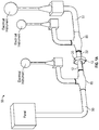
- FIG. 1 is a perspective schematic of one embodiment of a drain fitting installed within an electrical raceway system.
- FIG. 1A is a perspective schematic of an alternative embodiment of a drain fitting installed within an electrical raceway system.
- FIG. 2 is a cross-section end view of the fitting through the tool engaging member with an embodiment of a threaded screen insert placed within a drain passage perpendicular to the throughbore.
- FIG. 2A is a cross-section end view of the fitting through the tool engaging member with an embodiment of a clip-in screen insert placed within the drain passage.
- FIG. 2B is a cross-section end view of the fitting through the tool engaging member with an embodiment of a conical screen insert placed within the drain passage.
- FIG. 3 is a cutaway, perspective view of a horizontal section of the fitting of the present invention.
- FIG. 4 is a plan view of the horizontal section of the fitting of FIG. 3 .
- FIG. 5 is a perspective view of the fitting as a nipple with external threads on the tubular member of the present invention.
- FIG. 5A is a perspective view of the fitting as a coupling with internal threads on the tubular member filter.
- FIG. 6 is a schematic of prior art drain fittings installed within an electrical raceway system.
- FIG. 7 is a cross-section side view of one embodiment of the present invention with a tapered diameter into the channel.
- FIG. 7A is a cross-section side view of an alternative embodiment of the fitting of the present invention with sides of the channel at a right angle with respect to the bore.
- drain coupling ( 10 ) with internal connections installed in an electrical raceway system ( 55 ) at a low point to allow gravity drainage of water accumulated as a result of moisture condensation within the electrical raceway system. Drain coupling ( 10 ) is situated between interconnected raceway section ( 50 ) and raceway section ( 51 ) as shown in FIG. 1 .
- drain nipple ( 12 ) with external threads can be installed between conventional junction tee fittings ( 85 ) as shown in FIG. 1A .
- a tool is used to rotate the fitting ( 10 , 12 ) using the tool engaging member ( 20 ) to thread or otherwise connect the connecting ends ( 60 , 62 ) ( FIGS. 5 and 5A ) to adjacent raceway section(s) ( 50 ), ( 51 ) and/or tee fitting(s) ( 85 ).
- the screen insert ( 13 , 80 , 113 A) is installed in the drain passage ( 25 , 25 A) ( FIGS. 2, 2A, 2B ).
- the drain coupling ( 10 ) or nipple ( 12 ) in FIGS. 1 and 1A replaces the juncture configuration ( 83 ) using raceway tee fitting ( 85 ) depicted in the prior art connecting sections ( 50 ) and ( 51 ) shown in FIG. 6 .
- the device ( 10 , 12 ) of the present invention decreases the installation time relative to that required to install the standard raceway tee fitting ( 85 ) illustrated in FIG. 6 , which includes a tee cover ( 86 ), gasket (not shown), reducer ( 87 ) and screen insert ( 15 ).
- drain coupling ( 10 ) or nipple ( 12 ) is significantly decreased by installation of drain coupling ( 10 ) or nipple ( 12 ), saving time and money in equipment and labor.
- wire ( 84 ) ( FIGS. 2, 2A, 2B ) is pulled through the fitting ( 10 , 12 ) in the same manner as conventional raceway conduit, nipples, couplings, etc.
- the drain coupling ( 10 ) or nipple ( 12 ) is a unitary piece that is lighter in weight and requires less space for installation, transport and storage, important considerations on an offshore platform.
- Drain coupling ( 10 ) or nipple ( 12 ) further comprise a cylindrical tubular member ( 22 ) of a pre-determined length with a throughbore ( 37 ) having a continuous diameter therethrough and a channel ( 24 ) formed inside at the drain passage ( 25 , 25 A, 35 ).
- Coupling ( 10 ) or nipple ( 12 ) can be made of galvanized steel, PVC piping, PVC coated steel, stainless steel, brass, or another suitable type of material that will not rust from moisture or corrosive environments.
- the tubular member ( 22 ) can have a length and diameter configured to accommodate any raceway size.
- the specific length of the tubular member ( 22 ) depends on the diameter of the tubular member ( 22 ) as required for the electrical raceway system ( 55 ), raceway sections ( 50 , 51 ) and/or the connecting fittings ( 85 ).
- the diameter of the tubular member ( 22 ) can be nominally at least 1 ⁇ 2 inch.
- the length of the opposing connection members ( 60 , 62 ) depend on the diameter and the length of tubular member ( 22 ).
- drain coupling ( 10 ) or nipple ( 12 ) of the present invention can be configured and manufactured to fit any electrical raceway.
- the drain coupling ( 10 ) or nipple ( 12 ) further comprise a unitary tool engaging member ( 20 ) which is generally centrally disposed as an enlarged section encircling tubular member ( 22 ) and protruding radially outward therefrom.
- Tool engaging member ( 20 ) further comprises a solid three-dimensional surface structure configured to cooperatively engage with a corresponding tool device.
- tool engaging member ( 20 ) has a hexagonal profile and is configured to cooperatively engage with a wrench having a complementary profile.
- tool engaging member ( 20 ) can be configured to support other torque tools that can be used to interconnect electrical raceways.
- the hexagonal tool engaging member ( 20 ) can be at least 7 ⁇ 8 inches in depth from an outer diameter of the tubular member ( 22 ) and at least 11 ⁇ 8 inches wide in axial length.
- the depth can be configured in length to support drain passage ( 25 , 25 A, 35 ) as shown in FIGS. 2, 2A, and 2B .
- First tubular portion ( 40 ) and opposing tubular portion ( 45 ) extend from opposing sides of tool engaging member ( 20 ) to respective distal ends as seen in FIGS. 5 and 5A .
- Drain coupling ( 10 ) or nipple ( 12 ) further comprise a first connection member ( 60 ) formed upon first tubular portion ( 40 ) and an opposing second connection member ( 62 ) formed upon opposing tubular portion ( 45 ).
- Each tubular portion is configured to cooperatively engage with raceways or raceway fittings within an electrical system ( 55 ) as depicted in FIGS. 1 and 1A .
- First connection member ( 60 ) and opposing second connection member ( 62 ) are shown as threaded and the threads can be internally or externally disposed, preferably female or male NPT or metric threads.
- connection members ( 60 , 62 ) can have a threaded length configured to accommodate the electrical raceway section or fitting of the system.
- drain coupling ( 10 ) or nipple ( 12 ) further comprise a drain passage ( 25 , 25 A) disposed within one section of the tool engaging member ( 20 ), perpendicularly aligned with throughbore ( 37 ) ( FIGS. 2, 2A, 2B ) and having a continuous diameter linearly extending therefrom.
- drain passage ( 25 A) can be a smooth bore extending downward.
- drain passage ( 25 A) has a diameter that can be at least 1/16 th of an inch.
- drain passage ( 25 ) has threads ( 48 ).
- the drain passage ( 25 ) is slightly larger at the external end and can have a diameter at least 1 ⁇ 2 inch to allow for connection to a threaded screen insert ( 13 ) which allows for drainage of condensation from the electrical raceway.
- drain passages ( 25 , 25 A) are perpendicularly aligned with throughbore ( 37 ) and extend linearly downward therefrom.
- connection members ( 60 , 62 ) have conventional NPT or metric threading as depicted in FIGS. 5, 5A .
- connection members ( 60 , 62 ) can be configured to support any electrical raceways or raceway fittings.
- Drain passage ( 25 , 25 A) can have a small diameter of 1/16th inch and/or a larger diameter of 1 ⁇ 2 inch as depicted in FIGS. 2, 2A and 2B .
- drain passage ( 35 ) is a smooth bore and extends through tool engaging member ( 20 ) and into the throughbore ( 37 ) of tubular member ( 20 ) at the cavity or groove ( 24 ).
- drain passage ( 25 A) linearly extends from the throughbore ( 37 ) (see FIG. 2A ) and has a larger-diameter threaded section ( 48 ) to facilitate drainage by cooperatively engaging with screen insert ( 13 ) or another fitting (see FIGS. 2A, 2B ).
- Threads ( 48 ) can be conventional NPT threading.
- FIG. 2A there is shown a screen insert ( 80 ) located at the end of the drain passage ( 25 A).
- Screen ( 80 ) can be made of plastic, stainless steel, aluminum, or another non-corrosive material.
- the outer end of the drain passage ( 25 A) is enlarged and has a radial channel ( 92 ) that receives the screen insert ( 80 ) therein.
- a fastener such as a spring-loaded clip mechanism ( 95 ) can be disposed within channel ( 92 ) to allow the screen insert ( 80 ) to be securely fastened therein.
- drain coupling ( 10 ) or nipple ( 12 ) While in use drain coupling ( 10 ) or nipple ( 12 ) is placed within the lowest gravity point within the electrical raceway system with the drain passage ( 25 , 25 A) located facing downward which allows condensate or oil to drain down and out.
- the present invention includes a transverse channel ( 24 , 24 A) is formed in an interior surface of the tool engaging member ( 20 ) and extends upwardly in an arc on opposing sides of a lowermost point of the channel ( 24 , 24 A) when the fitting ( 10 , 12 ) is disposed horizontally.
- the channel ( 24 ) has sides tapering at oblique angles to the surface of the throughbore ( 37 ).
- the channel ( 24 A) has walls that form 90 degree right angles on opposing sides.
- the channel ( 24 , 24 A) allows condensation to drain by gravity from the raceway ( 37 )
Abstract
Description
Claims (23)
Priority Applications (1)
| Application Number | Priority Date | Filing Date | Title |
|---|---|---|---|
| US15/292,318 US10686303B2 (en) | 2012-10-19 | 2016-10-13 | Drain nipple |
Applications Claiming Priority (2)
| Application Number | Priority Date | Filing Date | Title |
|---|---|---|---|
| US13/656,547 US9722403B2 (en) | 2012-10-19 | 2012-10-19 | Electrical raceway drain fitting |
| US15/292,318 US10686303B2 (en) | 2012-10-19 | 2016-10-13 | Drain nipple |
Related Parent Applications (1)
| Application Number | Title | Priority Date | Filing Date |
|---|---|---|---|
| US13/656,547 Continuation-In-Part US9722403B2 (en) | 2012-10-19 | 2012-10-19 | Electrical raceway drain fitting |
Publications (2)
| Publication Number | Publication Date |
|---|---|
| US20180109089A1 US20180109089A1 (en) | 2018-04-19 |
| US10686303B2 true US10686303B2 (en) | 2020-06-16 |
Family
ID=61904757
Family Applications (1)
| Application Number | Title | Priority Date | Filing Date |
|---|---|---|---|
| US15/292,318 Active US10686303B2 (en) | 2012-10-19 | 2016-10-13 | Drain nipple |
Country Status (1)
| Country | Link |
|---|---|
| US (1) | US10686303B2 (en) |
Families Citing this family (1)
| Publication number | Priority date | Publication date | Assignee | Title |
|---|---|---|---|---|
| FR3092890A1 (en) * | 2019-02-14 | 2020-08-21 | Cryl | HYDRAULIC DISCHARGE COUPLER |
Citations (5)
| Publication number | Priority date | Publication date | Assignee | Title |
|---|---|---|---|---|
| US1985012A (en) * | 1933-08-12 | 1934-12-18 | Lincoln Eng Co | Swivel |
| US4171209A (en) * | 1977-02-07 | 1979-10-16 | Thermal Con-Serv Corp. | Apparatus for removing condensate from steam lines, and the like |
| US4246926A (en) * | 1979-04-25 | 1981-01-27 | Morello Salvatore T | Apparatus for removing residual water from a water system |
| US4424989A (en) * | 1980-07-02 | 1984-01-10 | General Electric Company | Drain hole |
| US5796035A (en) * | 1996-03-12 | 1998-08-18 | Walker; Patrick A. | Conduit drain for use in non-hazardous locations |
-
2016
- 2016-10-13 US US15/292,318 patent/US10686303B2/en active Active
Patent Citations (5)
| Publication number | Priority date | Publication date | Assignee | Title |
|---|---|---|---|---|
| US1985012A (en) * | 1933-08-12 | 1934-12-18 | Lincoln Eng Co | Swivel |
| US4171209A (en) * | 1977-02-07 | 1979-10-16 | Thermal Con-Serv Corp. | Apparatus for removing condensate from steam lines, and the like |
| US4246926A (en) * | 1979-04-25 | 1981-01-27 | Morello Salvatore T | Apparatus for removing residual water from a water system |
| US4424989A (en) * | 1980-07-02 | 1984-01-10 | General Electric Company | Drain hole |
| US5796035A (en) * | 1996-03-12 | 1998-08-18 | Walker; Patrick A. | Conduit drain for use in non-hazardous locations |
Also Published As
| Publication number | Publication date |
|---|---|
| US20180109089A1 (en) | 2018-04-19 |
Similar Documents
| Publication | Publication Date | Title |
|---|---|---|
| US9086180B2 (en) | Quick connect fire and dust suppression system | |
| WO1984000201A1 (en) | Freeze resistant hose bib receptacle | |
| US20220296946A1 (en) | Push-to-connect-rotate-to-release sprinkler assembly and fitting | |
| US5983923A (en) | Water service box and connectors for PEX pipe | |
| US8944111B2 (en) | Pipe pitch apparatus, system and method of installation | |
| US10578233B2 (en) | Pulling device for flexible conduit tubing | |
| US20230369835A1 (en) | Apparatus and method for joining extended lengths of conduit | |
| US10686303B2 (en) | Drain nipple | |
| US9722403B2 (en) | Electrical raceway drain fitting | |
| US8931571B2 (en) | Fire sprinkler extension and head adaptor | |
| US10014673B2 (en) | Quick lock system for joining and aligning tubes, conduits and junction boxes | |
| US9762041B1 (en) | Quick lock system for joining and aligning tubes, conduits and junction boxes | |
| US10483734B2 (en) | Quick lock system for joining and aligning tubes, conduits and junction boxes | |
| US20220385051A1 (en) | Drain coupling for electrical conduits | |
| US20110253356A1 (en) | Replacement Fitting and Method of Installing Same | |
| KR101232319B1 (en) | A pipe connector | |
| JP5555481B2 (en) | How to install unwinding piping for sprinklers | |
| KR200448977Y1 (en) | Pipe connectors | |
| US7631902B2 (en) | Transition coupling | |
| US10483731B2 (en) | Methods for joining extended lengths of conduit | |
| KR102163221B1 (en) | Supporting apparatus of freezing protection heating cable inside the vertical pipe | |
| CN211574447U (en) | Connector with a locking member | |
| KR102228980B1 (en) | Supporting apparatus of freezing protection heating cable inside the vertical pipe | |
| MX2014014553A (en) | Pipe fitting. | |
| KR101276485B1 (en) | Pipe connecter |
Legal Events
| Date | Code | Title | Description |
|---|---|---|---|
| STCB | Information on status: application discontinuation |
Free format text: ABANDONED -- FAILURE TO RESPOND TO AN OFFICE ACTION |
|
| FEPP | Fee payment procedure |
Free format text: PETITION RELATED TO MAINTENANCE FEES GRANTED (ORIGINAL EVENT CODE: PTGR); ENTITY STATUS OF PATENT OWNER: SMALL ENTITY |
|
| STPP | Information on status: patent application and granting procedure in general |
Free format text: NON FINAL ACTION MAILED |
|
| STPP | Information on status: patent application and granting procedure in general |
Free format text: RESPONSE TO NON-FINAL OFFICE ACTION ENTERED AND FORWARDED TO EXAMINER |
|
| STPP | Information on status: patent application and granting procedure in general |
Free format text: FINAL REJECTION MAILED |
|
| STPP | Information on status: patent application and granting procedure in general |
Free format text: ADVISORY ACTION MAILED |
|
| STCV | Information on status: appeal procedure |
Free format text: NOTICE OF APPEAL FILED |
|
| STPP | Information on status: patent application and granting procedure in general |
Free format text: DOCKETED NEW CASE - READY FOR EXAMINATION |
|
| STPP | Information on status: patent application and granting procedure in general |
Free format text: NOTICE OF ALLOWANCE MAILED -- APPLICATION RECEIVED IN OFFICE OF PUBLICATIONS |
|
| STCF | Information on status: patent grant |
Free format text: PATENTED CASE |
|
| MAFP | Maintenance fee payment |
Free format text: PAYMENT OF MAINTENANCE FEE, 4TH YR, SMALL ENTITY (ORIGINAL EVENT CODE: M2551); ENTITY STATUS OF PATENT OWNER: SMALL ENTITY Year of fee payment: 4 |