US10677347B2 - Deceleration control device of vehicle - Google Patents
Deceleration control device of vehicle Download PDFInfo
- Publication number
- US10677347B2 US10677347B2 US15/989,517 US201815989517A US10677347B2 US 10677347 B2 US10677347 B2 US 10677347B2 US 201815989517 A US201815989517 A US 201815989517A US 10677347 B2 US10677347 B2 US 10677347B2
- Authority
- US
- United States
- Prior art keywords
- deceleration
- shift
- vehicle
- range
- operational
- Prior art date
- Legal status (The legal status is an assumption and is not a legal conclusion. Google has not performed a legal analysis and makes no representation as to the accuracy of the status listed.)
- Active, expires
Links
Images


Classifications
-
- B—PERFORMING OPERATIONS; TRANSPORTING
- B60—VEHICLES IN GENERAL
- B60K—ARRANGEMENT OR MOUNTING OF PROPULSION UNITS OR OF TRANSMISSIONS IN VEHICLES; ARRANGEMENT OR MOUNTING OF PLURAL DIVERSE PRIME-MOVERS IN VEHICLES; AUXILIARY DRIVES FOR VEHICLES; INSTRUMENTATION OR DASHBOARDS FOR VEHICLES; ARRANGEMENTS IN CONNECTION WITH COOLING, AIR INTAKE, GAS EXHAUST OR FUEL SUPPLY OF PROPULSION UNITS IN VEHICLES
- B60K20/00—Arrangement or mounting of change-speed gearing control devices in vehicles
- B60K20/02—Arrangement or mounting of change-speed gearing control devices in vehicles of initiating means
-
- F—MECHANICAL ENGINEERING; LIGHTING; HEATING; WEAPONS; BLASTING
- F16—ENGINEERING ELEMENTS AND UNITS; GENERAL MEASURES FOR PRODUCING AND MAINTAINING EFFECTIVE FUNCTIONING OF MACHINES OR INSTALLATIONS; THERMAL INSULATION IN GENERAL
- F16H—GEARING
- F16H61/00—Control functions within control units of change-speed- or reversing-gearings for conveying rotary motion ; Control of exclusively fluid gearing, friction gearing, gearings with endless flexible members or other particular types of gearing
- F16H61/02—Control functions within control units of change-speed- or reversing-gearings for conveying rotary motion ; Control of exclusively fluid gearing, friction gearing, gearings with endless flexible members or other particular types of gearing characterised by the signals used
- F16H61/0202—Control functions within control units of change-speed- or reversing-gearings for conveying rotary motion ; Control of exclusively fluid gearing, friction gearing, gearings with endless flexible members or other particular types of gearing characterised by the signals used the signals being electric
- F16H61/0204—Control functions within control units of change-speed- or reversing-gearings for conveying rotary motion ; Control of exclusively fluid gearing, friction gearing, gearings with endless flexible members or other particular types of gearing characterised by the signals used the signals being electric for gearshift control, e.g. control functions for performing shifting or generation of shift signal
- F16H61/0213—Control functions within control units of change-speed- or reversing-gearings for conveying rotary motion ; Control of exclusively fluid gearing, friction gearing, gearings with endless flexible members or other particular types of gearing characterised by the signals used the signals being electric for gearshift control, e.g. control functions for performing shifting or generation of shift signal characterised by the method for generating shift signals
-
- B—PERFORMING OPERATIONS; TRANSPORTING
- B60—VEHICLES IN GENERAL
- B60K—ARRANGEMENT OR MOUNTING OF PROPULSION UNITS OR OF TRANSMISSIONS IN VEHICLES; ARRANGEMENT OR MOUNTING OF PLURAL DIVERSE PRIME-MOVERS IN VEHICLES; AUXILIARY DRIVES FOR VEHICLES; INSTRUMENTATION OR DASHBOARDS FOR VEHICLES; ARRANGEMENTS IN CONNECTION WITH COOLING, AIR INTAKE, GAS EXHAUST OR FUEL SUPPLY OF PROPULSION UNITS IN VEHICLES
- B60K25/00—Auxiliary drives
- B60K25/10—Auxiliary drives directly from oscillating movements due to vehicle running motion, e.g. suspension movement
-
- F—MECHANICAL ENGINEERING; LIGHTING; HEATING; WEAPONS; BLASTING
- F16—ENGINEERING ELEMENTS AND UNITS; GENERAL MEASURES FOR PRODUCING AND MAINTAINING EFFECTIVE FUNCTIONING OF MACHINES OR INSTALLATIONS; THERMAL INSULATION IN GENERAL
- F16H—GEARING
- F16H59/00—Control inputs to control units of change-speed- or reversing-gearings for conveying rotary motion
- F16H59/02—Selector apparatus
- F16H59/0204—Selector apparatus for automatic transmissions with means for range selection and manual shifting, e.g. range selector with tiptronic
-
- F—MECHANICAL ENGINEERING; LIGHTING; HEATING; WEAPONS; BLASTING
- F16—ENGINEERING ELEMENTS AND UNITS; GENERAL MEASURES FOR PRODUCING AND MAINTAINING EFFECTIVE FUNCTIONING OF MACHINES OR INSTALLATIONS; THERMAL INSULATION IN GENERAL
- F16H—GEARING
- F16H59/00—Control inputs to control units of change-speed- or reversing-gearings for conveying rotary motion
- F16H59/02—Selector apparatus
- F16H59/04—Ratio selector apparatus
-
- F—MECHANICAL ENGINEERING; LIGHTING; HEATING; WEAPONS; BLASTING
- F16—ENGINEERING ELEMENTS AND UNITS; GENERAL MEASURES FOR PRODUCING AND MAINTAINING EFFECTIVE FUNCTIONING OF MACHINES OR INSTALLATIONS; THERMAL INSULATION IN GENERAL
- F16H—GEARING
- F16H61/00—Control functions within control units of change-speed- or reversing-gearings for conveying rotary motion ; Control of exclusively fluid gearing, friction gearing, gearings with endless flexible members or other particular types of gearing
- F16H61/21—Providing engine brake control
-
- B—PERFORMING OPERATIONS; TRANSPORTING
- B60—VEHICLES IN GENERAL
- B60K—ARRANGEMENT OR MOUNTING OF PROPULSION UNITS OR OF TRANSMISSIONS IN VEHICLES; ARRANGEMENT OR MOUNTING OF PLURAL DIVERSE PRIME-MOVERS IN VEHICLES; AUXILIARY DRIVES FOR VEHICLES; INSTRUMENTATION OR DASHBOARDS FOR VEHICLES; ARRANGEMENTS IN CONNECTION WITH COOLING, AIR INTAKE, GAS EXHAUST OR FUEL SUPPLY OF PROPULSION UNITS IN VEHICLES
- B60K25/00—Auxiliary drives
- B60K25/10—Auxiliary drives directly from oscillating movements due to vehicle running motion, e.g. suspension movement
- B60K2025/103—Auxiliary drives directly from oscillating movements due to vehicle running motion, e.g. suspension movement by electric means
-
- B—PERFORMING OPERATIONS; TRANSPORTING
- B60—VEHICLES IN GENERAL
- B60Y—INDEXING SCHEME RELATING TO ASPECTS CROSS-CUTTING VEHICLE TECHNOLOGY
- B60Y2200/00—Type of vehicle
- B60Y2200/90—Vehicles comprising electric prime movers
- B60Y2200/92—Hybrid vehicles
-
- B—PERFORMING OPERATIONS; TRANSPORTING
- B60—VEHICLES IN GENERAL
- B60Y—INDEXING SCHEME RELATING TO ASPECTS CROSS-CUTTING VEHICLE TECHNOLOGY
- B60Y2300/00—Purposes or special features of road vehicle drive control systems
- B60Y2300/18—Propelling the vehicle
- B60Y2300/18008—Propelling the vehicle related to particular drive situations
- B60Y2300/18108—Braking
- B60Y2300/18125—Regenerative braking
-
- F—MECHANICAL ENGINEERING; LIGHTING; HEATING; WEAPONS; BLASTING
- F16—ENGINEERING ELEMENTS AND UNITS; GENERAL MEASURES FOR PRODUCING AND MAINTAINING EFFECTIVE FUNCTIONING OF MACHINES OR INSTALLATIONS; THERMAL INSULATION IN GENERAL
- F16H—GEARING
- F16H59/00—Control inputs to control units of change-speed- or reversing-gearings for conveying rotary motion
- F16H59/02—Selector apparatus
- F16H59/08—Range selector apparatus
- F16H2059/082—Range selector apparatus for different transmission modes
-
- F—MECHANICAL ENGINEERING; LIGHTING; HEATING; WEAPONS; BLASTING
- F16—ENGINEERING ELEMENTS AND UNITS; GENERAL MEASURES FOR PRODUCING AND MAINTAINING EFFECTIVE FUNCTIONING OF MACHINES OR INSTALLATIONS; THERMAL INSULATION IN GENERAL
- F16H—GEARING
- F16H61/00—Control functions within control units of change-speed- or reversing-gearings for conveying rotary motion ; Control of exclusively fluid gearing, friction gearing, gearings with endless flexible members or other particular types of gearing
- F16H61/02—Control functions within control units of change-speed- or reversing-gearings for conveying rotary motion ; Control of exclusively fluid gearing, friction gearing, gearings with endless flexible members or other particular types of gearing characterised by the signals used
- F16H61/0202—Control functions within control units of change-speed- or reversing-gearings for conveying rotary motion ; Control of exclusively fluid gearing, friction gearing, gearings with endless flexible members or other particular types of gearing characterised by the signals used the signals being electric
- F16H61/0204—Control functions within control units of change-speed- or reversing-gearings for conveying rotary motion ; Control of exclusively fluid gearing, friction gearing, gearings with endless flexible members or other particular types of gearing characterised by the signals used the signals being electric for gearshift control, e.g. control functions for performing shifting or generation of shift signal
- F16H61/0213—Control functions within control units of change-speed- or reversing-gearings for conveying rotary motion ; Control of exclusively fluid gearing, friction gearing, gearings with endless flexible members or other particular types of gearing characterised by the signals used the signals being electric for gearshift control, e.g. control functions for performing shifting or generation of shift signal characterised by the method for generating shift signals
- F16H2061/0234—Adapting the ratios to special vehicle conditions
-
- Y—GENERAL TAGGING OF NEW TECHNOLOGICAL DEVELOPMENTS; GENERAL TAGGING OF CROSS-SECTIONAL TECHNOLOGIES SPANNING OVER SEVERAL SECTIONS OF THE IPC; TECHNICAL SUBJECTS COVERED BY FORMER USPC CROSS-REFERENCE ART COLLECTIONS [XRACs] AND DIGESTS
- Y02—TECHNOLOGIES OR APPLICATIONS FOR MITIGATION OR ADAPTATION AGAINST CLIMATE CHANGE
- Y02T—CLIMATE CHANGE MITIGATION TECHNOLOGIES RELATED TO TRANSPORTATION
- Y02T10/00—Road transport of goods or passengers
- Y02T10/60—Other road transportation technologies with climate change mitigation effect
- Y02T10/72—Electric energy management in electromobility
Definitions
- the present invention relates to a deceleration control device of a vehicle provided with a shift lever.
- Japanese Patent Laid-Open Publication No. 9-317872 discloses a technology in which a shift map for engine brake is adjusted in accordance with the number of times of operation to a low speed stage (low-speed gear ratio).
- Japanese Patent Laid-Open Publication No. 2015-152053 discloses a technology in which an engine-brake force which is resistance of a power plant is changed in accordance with the number of times of operation of a shift lever from a D-range position to a B range which is provided beside the D-range position.
- a deceleration control device in which a shift lever is operable for selecting at least a D range, an R range, an N range (neutral range), a P range (parking range), and a B range and an M range which are selected for obtaining shift-down feeling of the automatic transmission which is expected when an accelerator is eased off.
- the deceleration control using resistance which is caused by a loss or regeneration of the power plant in a driven state through above-described shift lever operation preferably reduces burden of a frictional type of brake device of a normal foot brake, suppresses wear of the brake device, or prevents vaper lock or fade phenomenon of the brake device in vehicle's traveling on a steep down slope.
- a conventional device has a problem that the shift-lever operation for requesting the shift down needs plural times of operation when a driver conducts two or more stages of shift down for wanting large deceleration of the vehicle, so that the desired deceleration may not be obtained easily and promptly. That is, there is a concern that one-time operation of the shift lever for providing one-stage shift down may not achieve the desired deceleration. In this case, the shift down for the two-stage shift down may be finally required by operating the shift down twice, or the shift down for the three-stage shift down may be finally required by operating the shift down three times.
- a recently-used multi-stage type of stepped automatic transmission adopts a forward many-stage type, such as a forward 8-stage, 9-stage, or 10-stage type, so that a change amount in the gear ratio between adjacent shift stages becomes so small that the one-stage shift down may not create sufficient deceleration any more.
- the maximum shift stage to be obtained since the maximum shift stage to be obtained is merely restricted, there may exist a case where the shift down is not performed when the shift lever is operated from the D range to the S range or the L range. That is, when the current shift stage in the D range corresponds to the shift stage which is lower than the maximum shift stage to be obtained in the S range or the L range, no shift down may be performed even if the shift lever is operated to the S range or the L range.
- an object of the present invention is to provide a deceleration control device of a vehicle provided with a shift lever which can promptly obtain the desired deceleration through the one-time operation of the shift lever.
- the resistance force to decelerate the vehicle which is caused by the deceleration changing mechanism is controlled so as to be larger when the operational quantity of the one-time operation of the shift lever operated toward the deceleration-requesting position is larger, the deceleration desired by a driver can be obtained easily and promptly over a wide range from the smaller deceleration to the larger deceleration.
- the deceleration changing mechanism is an automatic transmission which changes the drive state of the driving wheel
- the controller is configured to control a gear ratio of the automatic transmission
- the gear ratio of the automatic transmission controlled by the controller is shifted down to a low-speed side such that the deceleration of the vehicle is larger when the operational quantity detected by the operational-quantity detector is larger.
- the shift down to the shift stage (gear ratio) to obtain the deceleration desired by the driver can be performed at one time in the vehicle to which the automatic transmission is installed.
- the automatic transmission is a stepped automatic transmission having plural shift stages
- the controller is configured to control the automatic transmission such that the number of stage of speed change to shift down by the automatic transmission is more when the operational quantity detected by the operational-quantity detector is larger.
- the shift down to the shift stage (gear ratio) to obtain the deceleration desired by the driver can be performed at one time in the vehicle to which the widely-used stepped automatic transmission having the plural shift stages is installed.
- the maximum of the number of stage of speed change to shift down which is controlled by the controller is two.
- This embodiment is preferable in the automatic transmission having the small number of forward-traveling stages in which the change amount in the gear ratio between the adjacent shift stages is large.
- the maximum of the number of stage of speed change to shift down which is controlled by the controller is three of more.
- This embodiment is preferable in the automatic transmission having the large number of forward-traveling stages in which the change amount in the gear ratio between the adjacent shift stages is small.
- the deceleration changing mechanism is a generator which is driven by an engine of the vehicle and capable of generating power for regeneration, the controller is configured to control a regenerative power-generation quantity generated by the generator, and the regenerative power-generation quantity of the generator controlled by the controller is increased such that the deceleration of the vehicle is larger when the operational quantity detected by the operational-quantity detector is larger.
- the deceleration desired by the driver can be obtained easily and promptly by using the generator which can perform the regenerative power generation to cause the resistance force to decelerate the vehicle.
- the deceleration changing mechanism comprises an automatic transmission which changes the drive state of the driving wheel and a generator which is driven by an engine of the vehicle and capable of generating power for regeneration, the controller is configured to concurrently control a gear ratio of the automatic transmission and a regenerative power-generation quantity generated by the generator, and the gear ratio of the automatic transmission controlled by the controller is shifted down to a low-speed side and the regenerative power-generation quantity of the generator controlled by the controller is increased such that the deceleration of the vehicle is larger when the operational quantity detected by the operational-quantity detector is larger.
- the deceleration desired by the driver can be obtained more easily and promptly by using both the shift-down control of the automatic transmission and the regenerative power-generation control of the generator.
- the deceleration control device further comprises a first determiner to determine target deceleration in accordance with the operational quantity detected by the operational-quantity detector, and a second determiner to determine the number of stage of speed change to shift down controlled by the automatic transmission and the regenerative power-generation quantity generated by the generator such that the target deceleration determined by the first determiner is obtained, wherein the controller is configured to perform the shift-down control of the automatic transmission by the number of stage of speed change to shift down determined by the second determiner and control the generator so as to generate the regenerative power-generation quantity determined by the second determiner.
- the deceleration can be properly adjusted at the target deceleration by harmoniously controlling the shift down by the automatic transmission and the regenerative power-generation quantity generated by the generator.
- the deceleration control device further comprises a shift gate for guiding a move of the shift lever, wherein the shift gate comprises a main gate portion where a parking range, a reverse range, a neutral range, and a drive range are arranged in series from one-end side of the shift gate toward the other-end side of the shift gate in order, a sub gate portion where a manual range and the deceleration-requesting position are arranged in series, and a connecting gate portion which interconnects a drive-range position of the main gate portion and a manual-range position of the sub gate portion, the main gate portion and the sub gate portion are arranged in parallel on right-and-left sides, and the deceleration-requesting position is configured to extend from the manual-range position toward a parking-range position.
- the shift gate comprises a main gate portion where a parking range, a reverse range, a neutral range, and a drive range are arranged in series from one-end side of the shift gate toward the other-end side of the shift gate in order, a sub gate
- the shift gate (a gate panel forming the shift gate) can be made properly small, and the operability of the shift lever can be made appropriate.
- the shift lever when the shift lever is operated toward the deceleration-requesting position, the shift lever is configured to be held at a current position as long as the shift lever is not operationally returned.
- the driver can easily recognize how much the desired deceleration is requested from a position of the shift lever which has been operated toward the deceleration-requesting position.
- the operational quantity detected by the operational-quantity detector includes a stroke of the shift lever.
- the deceleration desired by the driver can be properly detected in particular.
- FIG. 1 is a schematic plan view showing an example of a drive system of a vehicle to which the present invention is applied.
- FIG. 2 is a schematic plan view showing positions and moves of a shift lever.
- FIG. 3 is a major-part perspective view showing a structural example for obtaining swings, in a longitudinal direction and in a lateral direction, of the shift lever.
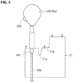
- FIG. 4 is a schematic side view showing a guide plate and the shift lever which are located between a P-range position and a D-range position.
- FIG. 5 is a schematic side view showing the guide plate and the shift lever which are located among an M-range position and deceleration-requesting positions.
- FIG. 6 is a block diagram showing an example of a control system of the present invention.
- FIG. 7 is a flowchart showing an example of a control of the present invention.
- FIG. 8 is a flowchart showing another example of the control of the present invention.
- FIG. 9 is a graph showing a relationship between a stroke of the shift lever operated toward the deceleration-requesting position and target decelerations.
- FIG. 10 is a schematic side view showing another structural example in which the guide plate and the shift lever which are constituted among the M-range position and the deceleration-requesting positions.
- FIG. 11 is a graph showing an example of setting of the stroke of the shift lever operated toward the deceleration-requesting positions and a load (reaction force).
- FIG. 12 is a graph showing an example of setting of the stroke of the shift lever operated toward the deceleration-requesting positions, the load (reaction force), and a shift-down stage.
- reference character 1 denotes an engine
- reference character 2 denotes a multi-stage (multi-gear ratio) type of stepped automatic transmission (which serves as a deceleration changing mechanism to change deceleration of a vehicle).
- An output of the engine 1 is transmitted to right-and-left driving wheels 6 L, 6 R through the automatic transmission 2 , a propeller shaft 3 , a deferential gear 4 , and right-and-left drive shafts 5 L, 5 R when a vehicle travels, being driven by the engine 1 .
- the automatic transmission 2 of a present embodiment is configured to be a forward 8-stage (1 st speed-8 th speed of gear ratios) automatic transmission
- the present invention is not limited to this type and any number-stage type of the automatic transmission is applicable, such as 6-stage, 7-stage or 10 stage.
- a rotational force of the driving wheels 6 L, 6 R is transmitted on the above-described path in a reverse direction, which provides a state in which engine braking (a resistance force to decelerate the vehicle) is generated.
- the quantity of the engine braking is changeable by changing the shift stage of the automatic transmission 2 . Further, the quantity of the engine braking is changeable by changing an opening of a throttle valve of the engine 1 .
- a generator 7 (which serves as another deceleration changing mechanism to change the deceleration of the vehicle) is driven by the engine 1 .
- the generator 7 is configured to be large-sized so as to obtain a large regenerative force positively.
- the resistance force to decelerate the vehicle can be increased more by making the generator 7 generate a power in addition to the above-described engine braking.
- the power generation of the generator 7 is changeable continuously (steplessly), so that the deceleration comprehensively obtained by both the engine braking and the power generation can be made continuous (substantially continuous).
- FIG. 2 shows a gate panel 10 which guides a shift lever, which will be describe later, of the automatic transmission 2 .
- This gate panel 10 is placed on an upper surface of a center console, for example.
- a P (parking) range, an R (reverse) range, an N (neutral) range, and a D (drive) range are arranged in series from a forward side to a rearward side in order as respective range positions.
- An M range (a manual range, which a specified position corresponds to) is arranged on a rightward side (a driver's seat side) of the D range.
- Deceleration-requesting positions B 1 , B 2 , B 3 are arranged in series toward the forward side from the M range in order.
- a shift-up position is provided in back of the M range.
- the shift lever serves as a kind of switch to command the gear-range shift, that is, the shift lever commands the gear-range shift in a fly-by-wire manner where an action does not mechanically act on an oil circuit of the automatic transmission.
- the shift lever operated by the driver is made extremely small-sized, and a size of the gate panel 10 is small accordingly.
- the small-sized gate panel 10 i.e., the shift lever
- a shift control with the shift lever is configured such that when the shift lever is operated to the deceleration-requesting position B 1 , the one-stage shift down (i.e., the move into low gear by one-gear ratio) is commanded. Further, when the shift lever is operated to the deceleration-requesting position B 2 , the two-stage shift down (i.e., the move into low gear by two-gear ratios) is commanded. When the shift lever is operated to the deceleration-requesting position B 3 , the three-stage shift down (i.e., the move into low gear by three-gear ratios) is commanded. These will be described specifically later. Moreover, when the shift lever is operated rearward from the M range, the shift up for one stage is commanded.
- Gate portions 10 A- 10 D (a gate hole formed at the gate panel 10 ) which constitute a shift gate are illustrated in a dash line in FIG. 2 . That is, the gate portion positioned between the P range and the D range is denoted by reference character 10 A (corresponding to a main gate portion), the gate portion positioned between the D range and the M range is denoted by reference character 10 B (corresponding to a connecting gate portion), the gate portion positioned between the M range and the foremost deceleration-requesting position B 3 is denoted by reference character 10 C (corresponding to a sub gate portion), and the gate portion positioned between the M range and a shift-up requesting position is denoted by reference character 10 D.
- the gate portion 10 D is designed so as to stop a retreat of the shift lever, which is configured to extremely short actually.
- a first member 21 which is held at a vehicle body is configured to be rotatable (swingable) around an axial line L 1 which extends in the longitudinal direction.
- a second member 22 which is held at the first member 21 is configured to be rotatable (swingable) around an axial line L 2 which extends in the lateral direction.
- a base end portion of the shift lever 20 is fixed to the second member 22 .
- a swing around the axial line L 2 is a move, in the longitudinal direction, of the shift lever 20 along the gate portions 10 A, 10 C and 10 D shown in FIG. 2 . Further, a swing around the axial line L 1 is a move, in the lateral direction, of the shift lever 20 along the gate portion 10 B.
- An upper end portion of the shift lever 20 is operated by the driver as an operational portion 20 a as shown in FIGS. 4 and 5 . Further, a guide pin 20 c is slidably attached to a rod portion 20 b which extends from the operational portion 20 a and is continuous to the second member 22 .
- a guide pin 20 c is biased upward by a spring, not illustrated. Further, the guide pin 20 c is configured to be displaceable downward by a specified degree against a biasing force of the spring when receiving an external force downward, but its further downward displacement is restricted by locking.
- a lock releasing button 20 d to be press-operated is provided at the operational portion 20 a , and the above-described locking is released by the driver's press-operating the lock releasing button 20 d , thereby allowing the guide pin 20 c to be displaced downward greatly.
- a step portion 11 a which protrudes downward greatly is formed at a portion of the guide panel 11 arranged below the gate panel 10 which is positioned between the P range and the D range, and another step portion 11 a is formed at another portion of the guide panel 11 which is positioned between the R range and the N range.
- the shift lever 20 is configured to be movable between the D range and the N range without operating the lock releasing button 20 d .
- the shift lever 20 is moved in a state where the lock releasing button 20 d is press-operated (where the guide pin 20 c is displaced downward greatly).
- moving of the shift lever 20 from the R range to the N range is allowed freely, but its moving from the N range to the R range is allowed in a state where the lock releasing button 20 d is press-operated.
- engaging recess portions 11 c , 11 d , 11 e are formed at the guide panel 11 at the respective deceleration-requesting positions B 1 , B 2 , B 3 .
- the shift lever 20 is held at its position. Some reaction force is generated so as to give a click (detent) feeling to the driver when the guide pin 20 d comes to be engaged with any of the engaging recess portions 11 d - 11 e or locking of the guide pin 20 d comes to be released.
- the shift lever 20 is moved between the deceleration-requesting positions B 1 -B 3 and the M range by operating the shift lever 20 in the longitudinal direction without press-operating the lock releasing button 20 d.
- the shift lever 20 When the shift lever 20 is operated rearward from the M range to the shift-up position, the shift lever 20 is automatically returned to the M range by means of a return spring, not illustrated, by releasing an operational force of the shift lever 20 .
- the position of the shift lever 20 is detected by sensors S 3 , S 4 .
- the sensor S 3 detects a swing position of the shift lever 20 swinging around the axial line L 1 . That is, the position, in the lateral direction, of the shift lever 20 , i.e., whether the shift lever 20 is positioned on a leftward side where the D range exists or on a rightward side where the M range exits, is determined by the sensor S 3 .
- the sensor S 4 detects the position, in the longitudinal direction, of the shift lever 20 . That is, the sensor S 4 detects where the shift lever 20 is positioned, i.e., which position of the P range, the R range, the N range, and the D range the shift lever 20 is located at, in a state where it is detected by the sensor S 3 that the shift lever 20 is positioned on the leftward side. Further, the sensor S 4 determines the M range, the deceleration-requesting position B 1 , the deceleration-requesting position B 2 , the deceleration-requesting position B 3 , or the shift-up position (the rearward swing from the M range) in a state where it is detected by the sensor S 3 that the shift lever 20 is positioned on the rightward side.
- detection of the shift-up requesting which is executed by the shift lever 20 being operated rearward from the M range can be performed by an additionally-provided switch.
- reference character U denotes a controller (control unit) which is constituted by a microcomputer. Signals from sensors S 1 , S 2 , additionally to the above-described sensors S 3 , S 4 , are inputted to the controller U.
- the sensor S 1 is a vehicle speed sensor to detect a vehicle speed.
- the sensor S 2 is an accelerator opening sensor to detect an accelerator opening (an engine load). Further, the controller U controls the automatic transmission 2 and the generator 7 .
- step Q 1 it is determined in step Q 1 whether or not the current range is the M range.
- the determination of the step Q 1 is NO, it is determined that the shift lever 20 is positioned at any of the P range, the R range, the N range, and the D range.
- the control in accordance with the range position where the shift lever 20 is positioned is performed in step Q 2 .
- the shift control of the automatic transmission 2 is performed based on a shift map where the vehicle speed and the accelerator opening are set as parameters, similarly to a conventional control.
- step Q 3 When the determination of the step Q 1 is YES, it is determined in step Q 3 whether or not the shift-up operation is conducted, that is, whether or not the shift lever 20 is operated rearward from the M range.
- step Q 4 it is determined in step Q 4 whether or not the current shift stage is the maximum shift stage (the 6 th speed in the present embodiment).
- the shift-up command for one-stage (one-gear ratio) shift up is outputted in step Q 5 (the one-stage shift-up control is performed at the automatic transmission 2 ).
- the current shift stage i.e., the maximum shift stage (the 6 th speed)
- step Q 7 it is determined in step Q 7 whether or not the shift-down operation is conducted, that is, whether or not the shift lever 20 is operated forward from the M range.
- the current shift stage (the current gear ratio) is maintained in step Q 8 .
- step Q 10 When the shift down set in the step Q 9 is performed, it is determined in step Q 10 whether or not the engine speed of the engine 1 exceeds a maximum allowable speed. When the determination of the step Q 10 is YES, 1 is deducted from the stag number DK determined in the step Q 9 , and then a control sequence is returned to the step Q 10 .
- step Q 12 the command to perform the shift down by the stage number DK at one time is outputted in step Q 12 .
- FIG. 8 shows another example of the control of the controller U, which corresponds to a processing after the determination of the step Q 3 being YES in FIG. 7 .
- target deceleration is set based on the operational quantity of the shift lever 20 in step Q 22 .
- the target deceleration is set, as shown in FIG. 9 , such that the target deceleration is larger when the forward stroke quantity of the shift lever 20 is larger.
- the target deceleration is set like a liner characteristic in FIG. 9 , a nonlinear characteristic such that an increase rate of the target deceleration is larger when the stroke is larger, for example, may be applied.
- the stage number DK to shift down for obtaining the target deceleration and a power generation quantity, i.e., a regenerative power-generation quantity, RE generated by the generator 7 are determined in step Q 23 . While changing of the deceleration by the shift down is stepwise, the deceleration can be changed continuously (substantially continuous) by continuously (continuously variably) changing the power generation quantity of the generator 7 .
- step Q 24 it is determined in step Q 24 whether or not the speed of the engine 1 exceeds the maximum allowable speed when the shift down is performed by the stage number DK.
- the determination of the step Q 24 is YES, 1 (one) is deducted from the stage number DK and the regenerative power-generation quantity RE is incremented for compensating this reduction of the stage number in step Q 24 .
- the control sequence is returned to the step Q 24 .
- step Q 24 When the determination of the step Q 24 is NO, the shift down is performed by the set stage number DK at one time and also the generator 7 is performed so that the power generation quantity becomes the quality RE in step Q 26 .
- FIG. 10 shows another embodiment of the present invention, which is a modified example of FIG. 5 .
- a step portion 11 f which extends downward is formed between the M range and the deceleration-requesting position.
- a forming position of the step portion 11 f is set between the deceleration-requesting positions B 1 , B 2 , so that the shift lever 20 cannot ride over this portion without press-operating the lock releasing button 20 c .
- the shift lever 20 is biased all the time so as to be returned to a home position between the deceleration-requesting position B 1 and the shift-up requesting position (a momentary type).
- the deceleration-requesting positions B 1 , B 2 are provided only, and the deceleration-requesting position B 3 is not provided (the shift down for the three-stage shift down is not performed).
- the shift lever 20 positioned at the M range is to be operated to the deceleration-requesting position B 2 , press-operating the lock releasing button 20 c .
- the driver can extremely clearly distinguish the two-stage shift down from the one-stage shift down.
- FIG. 11 shows a setting example of the stroke of the shift lever 20 and a load (an operational reaction force) when the shift lever 20 positioned at the M range is operated toward the deceleration-requesting position. It is set as a nonlinear characteristic such that an increase rate of the load is larger when the stroke is large. Thereby, the shift lever 20 can be operated lightly (i.e., with a light operational force) when the shift down with a small number of the shift stage is requested, and the load is heavier quickly when the shift-down stage number is larger. Accordingly, the driver can apparently recognize how many number of the shift stage is requested for the shift down from the load, i.e., the operational reaction force of the shift lever 20 .
- FIG. 12 shows a modified example of FIG. 11 .
- Setting of FIG. 12 is configured such that the load (operational reaction force) increases stepwise in accordance with an increase of the stroke.
- the driver can apparently recognize how many number of the shift stage is requested for the shift down from the load, i.e., the operational reaction force of the shift lever 20 .
- the transmission may be a continuously (steplessly) variable transmission or a type of transmission in which both a stepped transmission and a continuously variable transmission are provided and these two are controlled in a coordinated manner.
- the gear ratio of the continuously variable transmission can be continuously variably changed to a low-speed side, the desired deceleration of the vehicle can be continuously obtained easily.
- the gear ratio can be changed stepwise to the low-speed side, for example, in a three-step manner or a four or more-step manner.
- the generator 7 may be configured to serve as a motor in a drive traveling.
- the vehicle may be a front-wheel drive vehicle or a four-wheel drive vehicle.
- the motor may be a drive source.
- the deceleration changing can be controlled by adding a throttle control of the engine 1 .
- An operational force or an operational period may be applied as a parameter to represent the operational quantity of the shift lever 20 , not limited to the stroke of the shift lever 20 . Further, the operational quantity may be determined based on any one or combination of the stroke, the operational force, and the operational period of the shift lever. In particular, the driver can intuitively recognize the operational position of the shift lever (that is, the magnitude of the desired deceleration) by setting the stroke and the operational force which are combined such that the operational force is larger when the stroke is larger.
- the detection of the operational force as the operational quantity can be performed by a load sensor which receives a load when the shift lever 20 is operated toward the deceleration-requesting position side. In this case, the stroke of the shift lever 20 operated toward the deceleration-requesting position can be extremely small.
- the detection of the operational period as the operational quantity can be performed by a switch to detect the operation of the shift lever 20 toward the deceleration-requesting position. In this case, the stroke of the shift lever 20 operated toward the deceleration-requesting position can be extremely small.
- the number of shift-up stage may be set in accordance with the quantity of the one-time operation of the shift lever 20 similarly to the shift down, like the one-stage shift up, the two-stage shift up, or the three or more-stage shift up.
- the shift lever 20 may be configured to be automatically returned to the M range by releasing the operational force after the shift lever 20 is operated toward the deceleration-requesting positions B 1 -B 3 as a momentary type (a self-return type) between the M range and the deceleration-requesting positions B 1 -B 3 .
- the position detection of the shift lever 20 can be performed by any appropriate means, such as switches which are provided at respective ranges and deceleration-requesting positions.
- the maximum stage number of the shift down which is allowable at one time may be configured to be two, or four or more. In a case where the maximum number of forward traveling stage is five, for example, the maximum stage number of the shift down can be set at a small number like two, for example. Meanwhile, in a case where the maximum number of forward traveling stage is a large number, such as eight or ten, for example, the maximum stage number of the shift down can be set at 4 or more.
- the target deceleration (the deceleration to be achieved) can be compensated by the road surface gradient. That is, the deceleration in a case of a down slope can be compensated so as to be larger than that in a case of a flat surface road, and the deceleration in a case of an uphill rod is compensated so as to be smaller than that in the case in the flat surface road. Further, the deceleration can be compensated in accordance with a relative speed to a preceding vehicle immediately ahead of one's own vehicle.
- the deceleration can be compensated such that the deceleration becomes large when the relative speed to the preceding vehicle is high, and the deceleration becomes smaller when an approaching relative speed to the preceding vehicle is slow or when a separation relative speed from the preceding vehicle is high.
- the deceleration which is generated by a normal braking operation (by a foot brake) of the driver may be learned, and the deceleration may be compensated such that the deceleration becomes large when this learned deceleration is larger than a standard value (the deceleration becomes small when this learned deceleration is smaller than the standard value).
- Respective steps or a step group shown in the flowcharts can be expressed by adding means to names of their functions.
- the object of the present invention includes not only the clearly-described ones but implicitly includes providing things expressed as preferable matters or merits.
Landscapes
- Engineering & Computer Science (AREA)
- General Engineering & Computer Science (AREA)
- Mechanical Engineering (AREA)
- Chemical & Material Sciences (AREA)
- Combustion & Propulsion (AREA)
- Transportation (AREA)
- Control Of Transmission Device (AREA)
- Hybrid Electric Vehicles (AREA)
- Electric Propulsion And Braking For Vehicles (AREA)
- Arrangement Or Mounting Of Control Devices For Change-Speed Gearing (AREA)
Abstract
Description
Claims (11)
Applications Claiming Priority (2)
| Application Number | Priority Date | Filing Date | Title |
|---|---|---|---|
| JP2017-127310 | 2017-06-29 | ||
| JP2017127310A JP6525028B2 (en) | 2017-06-29 | 2017-06-29 | Deceleration control device in a vehicle provided with a shift lever |
Publications (2)
| Publication Number | Publication Date |
|---|---|
| US20190003584A1 US20190003584A1 (en) | 2019-01-03 |
| US10677347B2 true US10677347B2 (en) | 2020-06-09 |
Family
ID=64662110
Family Applications (1)
| Application Number | Title | Priority Date | Filing Date |
|---|---|---|---|
| US15/989,517 Active 2038-09-15 US10677347B2 (en) | 2017-06-29 | 2018-05-25 | Deceleration control device of vehicle |
Country Status (4)
| Country | Link |
|---|---|
| US (1) | US10677347B2 (en) |
| JP (1) | JP6525028B2 (en) |
| CN (1) | CN109203987B (en) |
| DE (1) | DE102018005040A1 (en) |
Families Citing this family (1)
| Publication number | Priority date | Publication date | Assignee | Title |
|---|---|---|---|---|
| EP4610082A1 (en) * | 2022-10-26 | 2025-09-03 | Kubota Corporation | Work vehicle |
Citations (13)
| Publication number | Priority date | Publication date | Assignee | Title |
|---|---|---|---|---|
| JPH0666369A (en) | 1993-04-26 | 1994-03-08 | Aisin Aw Co Ltd | Control device for vehicle power transmission device |
| JPH09196155A (en) | 1996-01-23 | 1997-07-29 | Nissan Motor Co Ltd | Transmission control device for automatic transmission |
| JPH09317872A (en) | 1996-05-28 | 1997-12-12 | Aqueous Res:Kk | Continuously variable transmission |
| EP0976954A2 (en) * | 1998-07-27 | 2000-02-02 | Ford Global Technologies, Inc. | Shift control system for an automatic transmission comprising a manual gear selecting control |
| JP2003267088A (en) | 2002-03-12 | 2003-09-25 | Toyota Motor Corp | Vehicle deceleration control device |
| JP2006022913A (en) | 2004-07-09 | 2006-01-26 | Nissan Motor Co Ltd | Engine brake control device with continuously variable transmission |
| US20060248976A1 (en) * | 2005-05-04 | 2006-11-09 | Dr. Ing. H.C.F. Porsche Aktiengesellschaft | Shifting mechanism for an automated or automatic transmission |
| US20110138955A1 (en) * | 2006-07-28 | 2011-06-16 | Dr. Ing. H.C. F. Porsche Aktiengesellschaft | Shift device for an automated or automatic transmission |
| JP2011133076A (en) | 2009-12-25 | 2011-07-07 | Fuji Heavy Ind Ltd | Continuously variable transmission |
| US20120166053A1 (en) * | 2010-12-24 | 2012-06-28 | Kabushiki Kaisha | Vehicle driving-force control device |
| US20130178333A1 (en) * | 2012-01-09 | 2013-07-11 | Zf Friedrichshafen Ag | Method for operating a transmission unit of a vehicle driveline with an engine |
| JP2015152053A (en) | 2014-02-12 | 2015-08-24 | マツダ株式会社 | Vehicle control device and vehicle control method |
| US10139001B2 (en) * | 2009-12-25 | 2018-11-27 | Subaru Corporation | Continuously variable transmission |
Family Cites Families (10)
| Publication number | Priority date | Publication date | Assignee | Title |
|---|---|---|---|---|
| JPS63199135A (en) * | 1987-02-16 | 1988-08-17 | Iseki & Co Ltd | Travel control device for vehicles, etc. |
| JP2575998Y2 (en) * | 1991-02-08 | 1998-07-02 | 日産ディーゼル工業株式会社 | Automatic transmission for vehicles |
| JP3708576B2 (en) * | 1995-03-13 | 2005-10-19 | ヤンマー農機株式会社 | Operation unit structure of hydraulic traveling agricultural machine |
| JP3528498B2 (en) * | 1997-02-24 | 2004-05-17 | 日産自動車株式会社 | Transmission control device for continuously variable transmission |
| JP2009035110A (en) * | 2007-08-01 | 2009-02-19 | Aisin Aw Co Ltd | Driving support method for vehicle with automatic transmission, driving support control program, and driving support device for vehicle with automatic transmission |
| JP6105213B2 (en) * | 2012-06-05 | 2017-03-29 | 富士重工業株式会社 | Shift control device for continuously variable transmission |
| JP6035234B2 (en) * | 2013-12-27 | 2016-11-30 | 本田技研工業株式会社 | Transmission control device |
| GB2525417B (en) * | 2014-04-24 | 2016-12-21 | Jaguar Land Rover Ltd | Cruise control system and method of operation |
| JP6108313B2 (en) * | 2014-07-01 | 2017-04-05 | 本田技研工業株式会社 | Engine start control device for hybrid vehicle |
| JP6649600B2 (en) * | 2015-08-03 | 2020-02-19 | 三菱自動車工業株式会社 | Regenerative control device for electric vehicles |
-
2017
- 2017-06-29 JP JP2017127310A patent/JP6525028B2/en active Active
-
2018
- 2018-05-25 US US15/989,517 patent/US10677347B2/en active Active
- 2018-06-25 DE DE102018005040.9A patent/DE102018005040A1/en not_active Ceased
- 2018-06-27 CN CN201810677243.7A patent/CN109203987B/en active Active
Patent Citations (13)
| Publication number | Priority date | Publication date | Assignee | Title |
|---|---|---|---|---|
| JPH0666369A (en) | 1993-04-26 | 1994-03-08 | Aisin Aw Co Ltd | Control device for vehicle power transmission device |
| JPH09196155A (en) | 1996-01-23 | 1997-07-29 | Nissan Motor Co Ltd | Transmission control device for automatic transmission |
| JPH09317872A (en) | 1996-05-28 | 1997-12-12 | Aqueous Res:Kk | Continuously variable transmission |
| EP0976954A2 (en) * | 1998-07-27 | 2000-02-02 | Ford Global Technologies, Inc. | Shift control system for an automatic transmission comprising a manual gear selecting control |
| JP2003267088A (en) | 2002-03-12 | 2003-09-25 | Toyota Motor Corp | Vehicle deceleration control device |
| JP2006022913A (en) | 2004-07-09 | 2006-01-26 | Nissan Motor Co Ltd | Engine brake control device with continuously variable transmission |
| US20060248976A1 (en) * | 2005-05-04 | 2006-11-09 | Dr. Ing. H.C.F. Porsche Aktiengesellschaft | Shifting mechanism for an automated or automatic transmission |
| US20110138955A1 (en) * | 2006-07-28 | 2011-06-16 | Dr. Ing. H.C. F. Porsche Aktiengesellschaft | Shift device for an automated or automatic transmission |
| JP2011133076A (en) | 2009-12-25 | 2011-07-07 | Fuji Heavy Ind Ltd | Continuously variable transmission |
| US10139001B2 (en) * | 2009-12-25 | 2018-11-27 | Subaru Corporation | Continuously variable transmission |
| US20120166053A1 (en) * | 2010-12-24 | 2012-06-28 | Kabushiki Kaisha | Vehicle driving-force control device |
| US20130178333A1 (en) * | 2012-01-09 | 2013-07-11 | Zf Friedrichshafen Ag | Method for operating a transmission unit of a vehicle driveline with an engine |
| JP2015152053A (en) | 2014-02-12 | 2015-08-24 | マツダ株式会社 | Vehicle control device and vehicle control method |
Also Published As
| Publication number | Publication date |
|---|---|
| JP2019011784A (en) | 2019-01-24 |
| CN109203987B (en) | 2021-10-15 |
| JP6525028B2 (en) | 2019-06-05 |
| CN109203987A (en) | 2019-01-15 |
| DE102018005040A1 (en) | 2019-01-03 |
| US20190003584A1 (en) | 2019-01-03 |
Similar Documents
| Publication | Publication Date | Title |
|---|---|---|
| US8409056B2 (en) | Vehicle driving force control device | |
| US10139001B2 (en) | Continuously variable transmission | |
| US10221941B2 (en) | Control device for automatic transmission | |
| JP4312592B2 (en) | Shift device for automatic transmission of vehicle | |
| US8777809B2 (en) | Method for operating a transmission unit of a vehicle driveline with an engine | |
| US6471619B2 (en) | Transmission control method | |
| CN106065941A (en) | The control device of vehicle | |
| JP2006526742A (en) | Method for operating a drive transmission system of an automobile | |
| US20120158258A1 (en) | Control apparatus for continuously variable transmission | |
| US20010039800A1 (en) | Control method for continuously variable transmission | |
| US10677347B2 (en) | Deceleration control device of vehicle | |
| JP7030183B2 (en) | Control device and control method for continuously variable transmission | |
| JP5310597B2 (en) | Continuously variable transmission | |
| US7608014B2 (en) | Deceleration control device for vehicle | |
| CN100470100C (en) | Improved approach to transition from drive to park | |
| JP4814013B2 (en) | Vehicle travel control device | |
| JP5150497B2 (en) | Method for driving an automatic or semi-automatic manual transmission for heavy vehicles in idling mode | |
| JP6610618B2 (en) | Deceleration control device for vehicle with shift lever | |
| JP2014199117A (en) | Hydraulic control device of belt type non-stage transmission | |
| JPH09317872A (en) | Continuously variable transmission | |
| JP2005042871A (en) | Shift control device for continuously variable transmission | |
| JP4618981B2 (en) | Shift control device for automatic transmission | |
| EP2716533A1 (en) | Straddle-type vehicle | |
| JP2006519966A (en) | Vehicle brake pedal interlock for shifting from neutral to meshing gear of heavy vehicles | |
| JP3497384B2 (en) | Work vehicle |
Legal Events
| Date | Code | Title | Description |
|---|---|---|---|
| AS | Assignment |
Owner name: MAZDA MOTOR CORPORATION, JAPAN Free format text: ASSIGNMENT OF ASSIGNORS INTEREST;ASSIGNORS:MATSUOKA, TOSHIHIRO;NAKATA, DAIKI;TOKUNAGA, KOUJI;AND OTHERS;REEL/FRAME:045902/0632 Effective date: 20180221 |
|
| FEPP | Fee payment procedure |
Free format text: ENTITY STATUS SET TO UNDISCOUNTED (ORIGINAL EVENT CODE: BIG.); ENTITY STATUS OF PATENT OWNER: LARGE ENTITY |
|
| STPP | Information on status: patent application and granting procedure in general |
Free format text: APPLICATION DISPATCHED FROM PREEXAM, NOT YET DOCKETED |
|
| STPP | Information on status: patent application and granting procedure in general |
Free format text: DOCKETED NEW CASE - READY FOR EXAMINATION |
|
| STPP | Information on status: patent application and granting procedure in general |
Free format text: NON FINAL ACTION MAILED |
|
| STPP | Information on status: patent application and granting procedure in general |
Free format text: RESPONSE TO NON-FINAL OFFICE ACTION ENTERED AND FORWARDED TO EXAMINER |
|
| STCF | Information on status: patent grant |
Free format text: PATENTED CASE |
|
| MAFP | Maintenance fee payment |
Free format text: PAYMENT OF MAINTENANCE FEE, 4TH YEAR, LARGE ENTITY (ORIGINAL EVENT CODE: M1551); ENTITY STATUS OF PATENT OWNER: LARGE ENTITY Year of fee payment: 4 |