US10675513B1 - Golf club with reduced air resistance club head - Google Patents
Golf club with reduced air resistance club head Download PDFInfo
- Publication number
- US10675513B1 US10675513B1 US15/950,990 US201815950990A US10675513B1 US 10675513 B1 US10675513 B1 US 10675513B1 US 201815950990 A US201815950990 A US 201815950990A US 10675513 B1 US10675513 B1 US 10675513B1
- Authority
- US
- United States
- Prior art keywords
- club
- club head
- spine structure
- segments
- slots
- Prior art date
- Legal status (The legal status is an assumption and is not a legal conclusion. Google has not performed a legal analysis and makes no representation as to the accuracy of the status listed.)
- Expired - Fee Related
Links
- XEEYBQQBJWHFJM-UHFFFAOYSA-N Iron Chemical compound [Fe] XEEYBQQBJWHFJM-UHFFFAOYSA-N 0.000 description 5
- 239000004576 sand Substances 0.000 description 5
- XLYOFNOQVPJJNP-UHFFFAOYSA-N water Substances O XLYOFNOQVPJJNP-UHFFFAOYSA-N 0.000 description 4
- 244000025254 Cannabis sativa Species 0.000 description 3
- 230000008901 benefit Effects 0.000 description 3
- 229910052742 iron Inorganic materials 0.000 description 3
- 239000000463 material Substances 0.000 description 3
- 239000007787 solid Substances 0.000 description 3
- 230000004048 modification Effects 0.000 description 2
- 238000012986 modification Methods 0.000 description 2
- 239000002023 wood Substances 0.000 description 2
- 230000005540 biological transmission Effects 0.000 description 1
- 238000013016 damping Methods 0.000 description 1
- 150000002505 iron Chemical class 0.000 description 1
- 238000004519 manufacturing process Methods 0.000 description 1
- 230000035939 shock Effects 0.000 description 1
- 238000006467 substitution reaction Methods 0.000 description 1
Images


Classifications
-
- A—HUMAN NECESSITIES
- A63—SPORTS; GAMES; AMUSEMENTS
- A63B—APPARATUS FOR PHYSICAL TRAINING, GYMNASTICS, SWIMMING, CLIMBING, OR FENCING; BALL GAMES; TRAINING EQUIPMENT
- A63B60/00—Details or accessories of golf clubs, bats, rackets or the like
- A63B60/52—Details or accessories of golf clubs, bats, rackets or the like with slits
-
- A—HUMAN NECESSITIES
- A63—SPORTS; GAMES; AMUSEMENTS
- A63B—APPARATUS FOR PHYSICAL TRAINING, GYMNASTICS, SWIMMING, CLIMBING, OR FENCING; BALL GAMES; TRAINING EQUIPMENT
- A63B53/00—Golf clubs
- A63B53/04—Heads
-
- A—HUMAN NECESSITIES
- A63—SPORTS; GAMES; AMUSEMENTS
- A63B—APPARATUS FOR PHYSICAL TRAINING, GYMNASTICS, SWIMMING, CLIMBING, OR FENCING; BALL GAMES; TRAINING EQUIPMENT
- A63B53/00—Golf clubs
- A63B53/04—Heads
- A63B53/0445—Details of grooves or the like on the impact surface
-
- A—HUMAN NECESSITIES
- A63—SPORTS; GAMES; AMUSEMENTS
- A63B—APPARATUS FOR PHYSICAL TRAINING, GYMNASTICS, SWIMMING, CLIMBING, OR FENCING; BALL GAMES; TRAINING EQUIPMENT
- A63B60/00—Details or accessories of golf clubs, bats, rackets or the like
- A63B60/006—Surfaces specially adapted for reducing air resistance
-
- A—HUMAN NECESSITIES
- A63—SPORTS; GAMES; AMUSEMENTS
- A63B—APPARATUS FOR PHYSICAL TRAINING, GYMNASTICS, SWIMMING, CLIMBING, OR FENCING; BALL GAMES; TRAINING EQUIPMENT
- A63B60/00—Details or accessories of golf clubs, bats, rackets or the like
- A63B60/50—Details or accessories of golf clubs, bats, rackets or the like with through-holes
-
- A—HUMAN NECESSITIES
- A63—SPORTS; GAMES; AMUSEMENTS
- A63B—APPARATUS FOR PHYSICAL TRAINING, GYMNASTICS, SWIMMING, CLIMBING, OR FENCING; BALL GAMES; TRAINING EQUIPMENT
- A63B2225/00—Miscellaneous features of sport apparatus, devices or equipment
- A63B2225/01—Special aerodynamic features, e.g. airfoil shapes, wings or air passages
-
- A—HUMAN NECESSITIES
- A63—SPORTS; GAMES; AMUSEMENTS
- A63B—APPARATUS FOR PHYSICAL TRAINING, GYMNASTICS, SWIMMING, CLIMBING, OR FENCING; BALL GAMES; TRAINING EQUIPMENT
- A63B53/00—Golf clubs
- A63B53/04—Heads
- A63B53/0466—Heads wood-type
-
- A—HUMAN NECESSITIES
- A63—SPORTS; GAMES; AMUSEMENTS
- A63B—APPARATUS FOR PHYSICAL TRAINING, GYMNASTICS, SWIMMING, CLIMBING, OR FENCING; BALL GAMES; TRAINING EQUIPMENT
- A63B53/00—Golf clubs
- A63B53/04—Heads
- A63B53/047—Heads iron-type
Definitions
- the present invention relates generally to the field of golf equipment. More specifically the present invention relates to a golf club having a club handle and a club head, the club head including a series of spaced apart club head segments interconnected by a spine structure.
- the club head segments are separated by parallel club head slots and have segment forward faces collectively forming a club head forward face for striking a ball.
- the slots are oriented relative to the club handle to be parallel to the direction of swing. Air directly enters and passes straight through the slots as the user swings the club rather than being deflected around the head, reducing air resistance.
- the spine structure extends transversely relative to the head segments, either through the middle or along the back of the club head.
- the overall shape of the club head, and the cross-sectional shape of the spine structure, are such that they minimize the resistance of air passing over them.
- the head segments at each lateral end of the head segment series have curved, contoured outward surfaces so that the ends of the club head are aerodynamic. The result is that the golfer is able to swing the club with greater speed and therefore to strike the ball with greater force.
- the cross-sectional shape of the spine structure is generally elongate in the direction of swing and substantially elliptical, much like an airplane wing.
- the spine structure cross-section preferably has pointed leading and trailing edges.
- the spine structure passes through the approximate center of each of the head segments.
- the club handle meets the club head in a conventional way, so that the club head is readily positioned to be perpendicular to the direction of swing.
- Moore, Jr. U.S. Patent Application Publication Number 2004/0152537, published on Aug. 5, 2004, discloses a golf club designed to minimize ground resistance.
- the Moore, Jr. club head has slots for passing sand and grass as the head contacts the ground during a swing, and it is noted that these slots may also reduce air resistance to some extent.
- the Moore, Jr. slots are in the lower portion of the club head only, rather than extending through the full height of the club head.
- a problem with Moore, Jr. is that the solid upper portion of the club head apparently produces as much air resistance as the upper portion of any conventional club head, and any reduced air resistance is minimal and purely incidental.
- Otoguro U.S. Pat. No. 6,517,449, issued on Feb. 11, 2003, discloses the structure of a head of a golf club iron. Otoguro discloses a series of small notches along the club head lower edge, similar to the slots of Moore, Jr., but less pronounced. As a result, any difference in air resistance between Otoguro and a conventional golf club head is likely to be either minimal or nonexistent.
- Asplund, et al. U.S. Pat. No. 6,846,246, issued on Jan. 25, 2005, teaches a slotted golf club head for reducing resistance caused by sand, water or grass when striking a ball.
- the club head has “a slotted lower portion having a plurality of slots for allowing an obstacle such as sand to pass through the golf club head” and an “un-slotted upper portion”, and is therefore similar to Moore, Jr.
- the striking surface is sharply angled and a cavity is provided in the rear surface.
- Bellfuss, Sr. U.S. Pat. No. 5,000,455, issued on Mar. 19, 1991, teaches a sand and water wedge for golf.
- Bellfuss, Sr. provides a golf club head having narrow grooves extending perpendicularly across slots which are intended to minimize drag caused by said and water during a swing. While Bellfuss, Sr., is intended to provide this benefit, the wedge shape and the minimal width of the openings produced by the intersecting grooves and slots seem insufficient to produce more than a negligible reduction in air resistance, and Bellfuss, Sr., apparently is not designed for that purpose.
- Gallagher U.S. Pat. No. 6,042,486, issued on Mar. 28, 2000, reveals a golf club head with a filled damping slot and an opening to a central cavity behind a floating club face.
- the striking face has a face aperture from front to back which is filled with a material intended to dampen the transmission of shock and vibration into the handle. No air passing slot appears to be provided.
- the present invention accomplishes the above-stated objectives, as well as others, as may be determined by a fair reading and interpretation of the entire specification.
- a golf club including a club handle; a club head including a series of spaced apart club head segments having segment forward faces collectively forming a club head forward face for striking a ball and being separated by substantially parallel club head slots oriented relative to the club handle to be substantially parallel to the direction of club swing so that air passes directly into and through the club head slots as a user swings the club, permitting the user to swing the club with greater speed and therefore to strike a ball with greater force, and a spine structure interconnecting the club head segments.
- the spine structure preferably extends transversely relative to the club head segments.
- the overall shape of the club head, and the cross-sectional shape of the spine structure preferably are selected so that they minimize the resistance of air passing over them.
- the club head segments at each lateral end of the series of the club head segments preferably have contoured outward surfaces so that opposing ends of the club head are aerodynamic.
- the cross-sectional shape of the spine structure preferably is generally elongate in the direction of a club swing.
- the cross-sectional shape of the spine structure optionally is substantially elliptical.
- the spine structure cross-section optionally has a sharp spine structure leading edge and a sharp spine structure trailing edge.
- the spine structure preferably intersects the approximate center of each of the club head segments.
- the widths of the individual head segments between the club head segments at opposing ends of the club head preferably are substantially uniform.
- the widths of the club head slots preferably are substantially uniform.
- the widths of the club head slots preferably are substantially uniform and substantially match the widths of the club head segments.
- FIG. 1 is a perspective view of the preferred embodiment of the present golf club with the upper portion of the handle omitted, where the golf club is in this instance a wood.
- FIG. 2 is a cross-sectional view of the club head of FIG. 1 , showing the profile of the spine structure of the preferred embodiment.
- FIG. 3 is a perspective view of a spine structure and a club head segment having a central port sized and aligned to receive the spine structure for an assembled version of the club head in which separate pieces are glued together, as distinguished from the version that is molded or cut from a single piece of material.
- FIG. 4 is a front plan view of the club head of FIG. 1 .
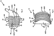
- FIG. 5 is a perspective view of the preferred embodiment, where club is an iron, and once again the upper portion of the handle omitted.
- FIG. 6 is a front plan view of the club head of FIG. 5 .
- FIG. 7 is a bottom plan view of the club head of FIG. 5 .
- a golf club 10 having a club handle 20 and a club head 40 , the club head 40 including a series of spaced apart club head segments 42 interconnected by a spine structure 60 .
- the club head segments 42 have segment forward faces 42 F and are separated by parallel club head slots 44 .
- the club head slots 44 are oriented relative to the club handle 20 and club face 42 F to be parallel to the direction of swing. As a result, air directly enters and passes through the club head slots 44 as the user swings the club 10 rather than being deflected around the head 40 , thereby reducing air resistance.
- the segment forward faces 42 F collectively form a club head forward face 40 F for striking a ball (not shown).
- the spine structure 60 extends transversely relative to the head segments 42 , either through the middle or along the back of the club head 40 .
- the overall shape of the club head 40 , and the cross-sectional shape of the spine structure 60 are such that they minimize the resistance of air passing over them.
- the cross-sectional shape of the spine structure is generally elongate in the direction of swing and substantially elliptical, much like an airplane wing.
- the spine structure cross-section preferably has pointed leading and trailing edges.
- the spine structure passes through the approximate center of each of the head segments.
- the club head segments 42 optionally each have a central port 42 P sized and aligned to receive the spine structure 60 for a version in which the club head 40 is assembled from separate pieces which are glued or otherwise fastened together, as shown in FIG. 3 .
- either the club head 40 or the entire golf club 10 is molded or cut from a single piece of material.
- FIGS. 1-4 illustrate the inventive club head 40 in the form of a wood
- FIGS. 5-7 illustrate the club head 40 in the form of an iron.
- the club handle 20 meets the club head 40 in a conventional way, so that the club head can be positioned to be perpendicular to the direction of swing.
- the widths of the individual club head segments 42 between the end head segments 42 E preferably are substantially uniform.
- the widths of the club head slots 44 preferably are substantially uniform.
- the widths of the club head slots 44 preferably are substantially uniform and preferably substantially match the widths of the head segments 42 .
Landscapes
- Health & Medical Sciences (AREA)
- General Health & Medical Sciences (AREA)
- Physical Education & Sports Medicine (AREA)
- Life Sciences & Earth Sciences (AREA)
- Engineering & Computer Science (AREA)
- Wood Science & Technology (AREA)
- Golf Clubs (AREA)
Abstract
Description
Claims (8)
Priority Applications (1)
| Application Number | Priority Date | Filing Date | Title |
|---|---|---|---|
| US15/950,990 US10675513B1 (en) | 2018-04-11 | 2018-04-11 | Golf club with reduced air resistance club head |
Applications Claiming Priority (1)
| Application Number | Priority Date | Filing Date | Title |
|---|---|---|---|
| US15/950,990 US10675513B1 (en) | 2018-04-11 | 2018-04-11 | Golf club with reduced air resistance club head |
Publications (1)
| Publication Number | Publication Date |
|---|---|
| US10675513B1 true US10675513B1 (en) | 2020-06-09 |
Family
ID=70972963
Family Applications (1)
| Application Number | Title | Priority Date | Filing Date |
|---|---|---|---|
| US15/950,990 Expired - Fee Related US10675513B1 (en) | 2018-04-11 | 2018-04-11 | Golf club with reduced air resistance club head |
Country Status (1)
| Country | Link |
|---|---|
| US (1) | US10675513B1 (en) |
Citations (20)
| Publication number | Priority date | Publication date | Assignee | Title |
|---|---|---|---|---|
| US780776A (en) * | 1904-04-12 | 1905-01-24 | James Ross Brown | Golfing-club. |
| US3719359A (en) * | 1970-09-08 | 1973-03-06 | F Evans | Sand wedge golf club |
| US3997170A (en) * | 1975-08-20 | 1976-12-14 | Goldberg Marvin B | Golf wood, or iron, club |
| US4065133A (en) * | 1976-03-26 | 1977-12-27 | Gordos Ambrose L | Golf club head structure |
| US4213613A (en) * | 1977-12-29 | 1980-07-22 | Nygren Gordon W | Golf club head with center of gravity near its striking face |
| JPH0975486A (en) * | 1995-09-18 | 1997-03-25 | Satoru Morita | Golf club |
| US5613915A (en) * | 1996-03-12 | 1997-03-25 | Van Alen, Jr.; William L. | Variable resistance golf training device |
| US5944614A (en) * | 1998-05-20 | 1999-08-31 | Yoon; Jong M. | Golf club head |
| USD425157S (en) * | 1999-08-13 | 2000-05-16 | Teardrop Golf Company | Golf putter head |
| JP2001314536A (en) * | 2000-05-02 | 2001-11-13 | Shusuke Wago | Golf club |
| US20040152537A1 (en) * | 2003-01-30 | 2004-08-05 | Moore Albert Edward | Low resistance golf club |
| US20050032584A1 (en) * | 2003-04-10 | 2005-02-10 | Van Nimwegen Robert Roy | Golf club, jetdrv driver for increased distance and accuracy |
| US20050064953A1 (en) * | 2003-03-27 | 2005-03-24 | Moore Albert E. | Low resistance golf club |
| US6969325B1 (en) * | 2004-03-30 | 2005-11-29 | David Harrelson | Golf club, a method for reducing the drag experienced by a golf club, and a golf club formed by a new and novel process which reduces drag as the golf club is utilized |
| US20060100027A1 (en) * | 2004-11-09 | 2006-05-11 | Wang Jessie L | Golf club head |
| US7121966B2 (en) * | 2001-09-27 | 2006-10-17 | Devin Ian Fitzmaurice | Apparatus and method for manipulating a ball |
| US20070142120A1 (en) * | 2005-12-20 | 2007-06-21 | Krewalk John J | Golf club |
| JP2008194116A (en) * | 2007-02-09 | 2008-08-28 | Fukuhara Imono Seisakusho:Kk | Head of golf club |
| US7641568B2 (en) * | 2006-11-30 | 2010-01-05 | Taylor Made Golf Company, Inc. | Golf club head having ribs |
| US8845453B1 (en) * | 2013-03-08 | 2014-09-30 | Callaway Golf Company | Golf club head with improved aerodynamic characteristics |
-
2018
- 2018-04-11 US US15/950,990 patent/US10675513B1/en not_active Expired - Fee Related
Patent Citations (20)
| Publication number | Priority date | Publication date | Assignee | Title |
|---|---|---|---|---|
| US780776A (en) * | 1904-04-12 | 1905-01-24 | James Ross Brown | Golfing-club. |
| US3719359A (en) * | 1970-09-08 | 1973-03-06 | F Evans | Sand wedge golf club |
| US3997170A (en) * | 1975-08-20 | 1976-12-14 | Goldberg Marvin B | Golf wood, or iron, club |
| US4065133A (en) * | 1976-03-26 | 1977-12-27 | Gordos Ambrose L | Golf club head structure |
| US4213613A (en) * | 1977-12-29 | 1980-07-22 | Nygren Gordon W | Golf club head with center of gravity near its striking face |
| JPH0975486A (en) * | 1995-09-18 | 1997-03-25 | Satoru Morita | Golf club |
| US5613915A (en) * | 1996-03-12 | 1997-03-25 | Van Alen, Jr.; William L. | Variable resistance golf training device |
| US5944614A (en) * | 1998-05-20 | 1999-08-31 | Yoon; Jong M. | Golf club head |
| USD425157S (en) * | 1999-08-13 | 2000-05-16 | Teardrop Golf Company | Golf putter head |
| JP2001314536A (en) * | 2000-05-02 | 2001-11-13 | Shusuke Wago | Golf club |
| US7121966B2 (en) * | 2001-09-27 | 2006-10-17 | Devin Ian Fitzmaurice | Apparatus and method for manipulating a ball |
| US20040152537A1 (en) * | 2003-01-30 | 2004-08-05 | Moore Albert Edward | Low resistance golf club |
| US20050064953A1 (en) * | 2003-03-27 | 2005-03-24 | Moore Albert E. | Low resistance golf club |
| US20050032584A1 (en) * | 2003-04-10 | 2005-02-10 | Van Nimwegen Robert Roy | Golf club, jetdrv driver for increased distance and accuracy |
| US6969325B1 (en) * | 2004-03-30 | 2005-11-29 | David Harrelson | Golf club, a method for reducing the drag experienced by a golf club, and a golf club formed by a new and novel process which reduces drag as the golf club is utilized |
| US20060100027A1 (en) * | 2004-11-09 | 2006-05-11 | Wang Jessie L | Golf club head |
| US20070142120A1 (en) * | 2005-12-20 | 2007-06-21 | Krewalk John J | Golf club |
| US7641568B2 (en) * | 2006-11-30 | 2010-01-05 | Taylor Made Golf Company, Inc. | Golf club head having ribs |
| JP2008194116A (en) * | 2007-02-09 | 2008-08-28 | Fukuhara Imono Seisakusho:Kk | Head of golf club |
| US8845453B1 (en) * | 2013-03-08 | 2014-09-30 | Callaway Golf Company | Golf club head with improved aerodynamic characteristics |
Similar Documents
| Publication | Publication Date | Title |
|---|---|---|
| US4930783A (en) | Golf club | |
| US11007410B2 (en) | Weighted iron set | |
| US10821338B2 (en) | Striking face deflection structures in a golf club | |
| US4900029A (en) | Golf club head with aerodynamic upper surface | |
| US6652390B2 (en) | Spread heel/toe weighted golf club | |
| US9168438B2 (en) | Golf club and golf club head structures | |
| US2007377A (en) | Golf club | |
| US10150019B2 (en) | Striking face deflection structures in a golf club | |
| US20140274441A1 (en) | Variable bounce height club heads and related methods | |
| US7056226B2 (en) | Golf club having stepped grooves | |
| US5916035A (en) | Golf putter head | |
| EP2910286A1 (en) | Golf club head with a wave sole | |
| US20180133565A1 (en) | Striking face deflection structures in a golf club | |
| US10702751B2 (en) | Weighted iron set | |
| US20120094779A1 (en) | Golf club head with undercut | |
| US20160193511A1 (en) | Variable bounce height club heads and related methods | |
| US12172057B2 (en) | Golf club head with sole rails | |
| US20130324307A1 (en) | Golf club and golf club head with a crown recessed feature | |
| US10675513B1 (en) | Golf club with reduced air resistance club head | |
| US20050064953A1 (en) | Low resistance golf club | |
| US20240374969A1 (en) | Supported iron | |
| US20120040772A1 (en) | Golf club head | |
| KR102696215B1 (en) | Golf putter head | |
| US20040152537A1 (en) | Low resistance golf club | |
| US20250018255A1 (en) | Golf club head with sole rails |
Legal Events
| Date | Code | Title | Description |
|---|---|---|---|
| FEPP | Fee payment procedure |
Free format text: ENTITY STATUS SET TO UNDISCOUNTED (ORIGINAL EVENT CODE: BIG.); ENTITY STATUS OF PATENT OWNER: MICROENTITY |
|
| FEPP | Fee payment procedure |
Free format text: ENTITY STATUS SET TO MICRO (ORIGINAL EVENT CODE: MICR); ENTITY STATUS OF PATENT OWNER: MICROENTITY |
|
| FEPP | Fee payment procedure |
Free format text: PETITION RELATED TO MAINTENANCE FEES GRANTED (ORIGINAL EVENT CODE: PTGR); ENTITY STATUS OF PATENT OWNER: MICROENTITY |
|
| ZAAA | Notice of allowance and fees due |
Free format text: ORIGINAL CODE: NOA |
|
| ZAAB | Notice of allowance mailed |
Free format text: ORIGINAL CODE: MN/=. |
|
| STCF | Information on status: patent grant |
Free format text: PATENTED CASE |
|
| FEPP | Fee payment procedure |
Free format text: MAINTENANCE FEE REMINDER MAILED (ORIGINAL EVENT CODE: REM.); ENTITY STATUS OF PATENT OWNER: MICROENTITY |
|
| LAPS | Lapse for failure to pay maintenance fees |
Free format text: PATENT EXPIRED FOR FAILURE TO PAY MAINTENANCE FEES (ORIGINAL EVENT CODE: EXP.); ENTITY STATUS OF PATENT OWNER: MICROENTITY |
|
| STCH | Information on status: patent discontinuation |
Free format text: PATENT EXPIRED DUE TO NONPAYMENT OF MAINTENANCE FEES UNDER 37 CFR 1.362 |
|
| FP | Lapsed due to failure to pay maintenance fee |
Effective date: 20240609 |