US1067258A - Internal-combustion engine. - Google Patents
Internal-combustion engine. Download PDFInfo
- Publication number
- US1067258A US1067258A US61599111A US1911615991A US1067258A US 1067258 A US1067258 A US 1067258A US 61599111 A US61599111 A US 61599111A US 1911615991 A US1911615991 A US 1911615991A US 1067258 A US1067258 A US 1067258A
- Authority
- US
- United States
- Prior art keywords
- retort
- cylinder
- power
- piston
- water
- Prior art date
- Legal status (The legal status is an assumption and is not a legal conclusion. Google has not performed a legal analysis and makes no representation as to the accuracy of the status listed.)
- Expired - Lifetime
Links
- 238000002485 combustion reaction Methods 0.000 title description 25
- XLYOFNOQVPJJNP-UHFFFAOYSA-N water Substances O XLYOFNOQVPJJNP-UHFFFAOYSA-N 0.000 description 58
- 239000007789 gas Substances 0.000 description 33
- 239000003921 oil Substances 0.000 description 18
- 239000000295 fuel oil Substances 0.000 description 16
- 239000000203 mixture Substances 0.000 description 10
- 239000000446 fuel Substances 0.000 description 5
- 239000013505 freshwater Substances 0.000 description 4
- 230000000717 retained effect Effects 0.000 description 4
- 238000010276 construction Methods 0.000 description 3
- 150000003839 salts Chemical class 0.000 description 3
- 102100035683 Axin-2 Human genes 0.000 description 2
- 101700047552 Axin-2 Proteins 0.000 description 2
- 238000009833 condensation Methods 0.000 description 2
- 230000005494 condensation Effects 0.000 description 2
- 238000004880 explosion Methods 0.000 description 2
- 239000008246 gaseous mixture Substances 0.000 description 2
- 235000017276 Salvia Nutrition 0.000 description 1
- 241001072909 Salvia Species 0.000 description 1
- ATJFFYVFTNAWJD-UHFFFAOYSA-N Tin Chemical compound [Sn] ATJFFYVFTNAWJD-UHFFFAOYSA-N 0.000 description 1
- 230000004075 alteration Effects 0.000 description 1
- 230000006835 compression Effects 0.000 description 1
- 238000007906 compression Methods 0.000 description 1
- 238000001816 cooling Methods 0.000 description 1
- 238000004519 manufacturing process Methods 0.000 description 1
- 229920000136 polysorbate Polymers 0.000 description 1
- 239000011435 rock Substances 0.000 description 1
- 235000002020 sage Nutrition 0.000 description 1
- 230000013707 sensory perception of sound Effects 0.000 description 1
Images


Classifications
-
- F—MECHANICAL ENGINEERING; LIGHTING; HEATING; WEAPONS; BLASTING
- F02—COMBUSTION ENGINES; HOT-GAS OR COMBUSTION-PRODUCT ENGINE PLANTS
- F02M—SUPPLYING COMBUSTION ENGINES IN GENERAL WITH COMBUSTIBLE MIXTURES OR CONSTITUENTS THEREOF
- F02M1/00—Carburettors with means for facilitating engine's starting or its idling below operational temperatures
Definitions
- This invention relates to certain improvements in internal combustion engines and particularly to that class of engines shown and described in Letters Patent ranted to me. March 3, 1908. and September 13, 1010, Nos. 880,744, and 070,063, respectively, and in my (re-pendin applications filed March 22, 1010, Serial L 0. 551,018, and November 21, 1910, Serial No. 593,562.
- the ohject'of the invention is to provide -a cheap, simple and highly etlicint heavy oil engine that is particularly adapted for marine uses and wherein fuel oil and water or steam are injected into a retort or furnace and there converted into a combustible gas which, at the proper time, is forced into the combustion chamber of the working cylinder and there ignited to drive the piston on its power stroke.
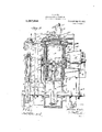
- Figure 1 is a side elevationjof the engine.
- l ig. Q is a vertical longitudinal section of same.
- Fig. 23 is a vertical section on a lar er scale of the upper end of the power cylin er and the cylinder head.
- Fig. 4 is a transverse section drawn on the line 1-4 of Fig.
- the cylinder A is mounted upon a min ably closed crank-case A which is prm him! with bearings a for the main crap hair it of the engine.
- the cylinder A is water jacketed and in its side walls are arranged a plurality of, eXhaiiSt ports A' which open into an annular exhaust passag A'- t rmed in a water jacketed casing A which is r em. upon the outer walls of the cylindriz exhaust pipe A is connected to the to carry off the exhaust gases to any o point.
- the upper end of the cylinder A is closed by a Water jacketed cylinder head i) which is provided with a transverse rece s l) in its lower side that extends entirely across the bore of the cylinder and which is formed by an upwardly extending semicircular and: h that is cast integral with the said in a l in tilt i t'llilf fig iii' lit lti l lid- ' is formed with a valve casing secured to the upper end of the one side of the head is a bore d that leads into the recess D and in this bore is held the outer end of a retort or furnace E of smaller diameter than the recess and which extends entirely across the upper end of the cylinder and has its inner end terminated a short distance from the adjacent end of the recess D.
- a perforated disk E which is also provided with a central opening in which is held an oil feed pipe G and a water feed pipe H whose inner ends extend into the retort or furnace and whose outer ends connect with suitable feed pumps G and H respectively, Fig. 2.
- the pistons (shown in dotted lines) of the pumps are operated by cams 9 carried by the main crank shaft of the engine. Fitted within the extreme outer end of the retort or furnace is a short tubular sleeve I whose outer.
- the disk i is formed with a central opening through which the pipes G and H pass and below this opening is an opening in which is held the outer end of a compressed air feed pipe J extendingfrom an air compression pump J having a piston J which is operated by a crank j on the main crankshaft of the engine through the connecting rod j
- the cylinder of the pump J is provided adjacent to its upper'end with trunnions j which are journaled in hearings in a frame 7' so as to permit an oscillating movement of the cylinder that is caused through the rotation of the crank -j.
- the upper end of the cylinder is provided with a valve controlled inlet port j and an outlet port j which latter is "controlled by an outwardly opening valve 7' carried in a nest of wires when forced through the pipes G and H.
- the wires L are closely assembled within the retort or furnace with the outer layer held against the walls of the retort and with the remaining layers or members of the group contacting with each other so as to form a compact mass to take up the heat from the walls of the retort as the latter he comes hot from the explosions in the power cylinder and thereby transfer the heat to all the wires of the nest.
- the rod M is shifted from one side of the pivot of lever R to the other.
- the engine is slowed down, and as the piston nears the end of its return stroke, the rod is thrown over, thereby cutting off the supply to the.
- retort and power fuel is admitted and the charge ignited 1ust' before the piston reaches the end of its return stroke and just before the crank 1) reaches a vertical position, or is on the dead center so that as the charge is ignited to drive the piston on its next power stroke the shaft will be turned in the opposite direction.
- valve casing O designates a steam dome that is connected to the water jacket of the cylinder head D through a pipe 0 and connected to thh upper end of the steam dome is valve casing O to which is connected one end of a pipe whose opposite end is held in a port, 0 in the cylinder head and leads into the recess D.
- a spring closed valve 0 controls the passage through the pipe and the stem of the valve carries an-upwardly extending lever armO that is en cylinder.
- Extending from the valve casing is a flexible pipe section 7' whose opposite end is connected to the inlet port of a valve casin K to the outlet port of which is connecte the inner end of the compressed air supply pipe J.
- the valve K of the casing K is operated by a crank armK as will be later described.
- the retort or furnace E is held a nest of heat conducting wires L against and between which the fuel oil and the water are forced when injected into the retort through the pipes G and H.
- These wires have their ends adjacent to the disk E arranged so as to form a funnel-shape mouth or entrance which serves to catch'and scatter the oil and the water throughout thewhole group or.
- M is a con-' a safetycylinder and causing the engine to miss fire once.
- Q designates a water supply tank which is connected by a. )ipe Q that extends to a suitable pump Q from which extends a supply pipe Q, that is connected to the, water jacket. of the cylinder A.
- the piston of the pump is operated by an eccentric 4 carried by the main shaft 12.
- a second pipe S is also connected to the supply tank Q for supplying water t the pump H.
- the engine is especially designed for marine uses and in order to avoid the necessity of carrying large quantities of fresh water for its use
- Salt water is fed into the evap orator through a pipe S which extends from a pump (not shown) which in turn communicates with the sea.
- the operation of the engine is as follows: Let it be assumed that the engine isrun'ning and that the retort or furnace and the nest of wires therein have become hot from the explosions of the previous charges injected into the'working end of the power cylinder, and also that a charge has just been ignited to drive the power piston on its power stroke. As the piston begins its power stroke a charge of fuel oil and of water is forced into the retort or furnace through the pipe (i and II, respectively, against the nest of hot wires and converted into a gaseous mixture.
- This mixture remains in the retort or furnace during nearly the com-' the up-stroke of the piston J to escape into the retort or furnace and drive the gaseous mixture out through the openings between the nest of wires L, through the perforated disk L and into the upper end of the ower cylinder and the space surrounding the retort or furnace where the gas and the compressed air are thoroughly mixed and compressed by the piston into a combustible mixture.
- the piston by this time having reached the end of its up stroke the mixture instantly ignites to drive the piston on its next down or power stroke. As the piston nears the end of its power st oke the exhaust ports A are first uncovere' to p.
- What l claim is 1.
- the combination with a power cvlinder, a piston working therein, a power shaft, and a into a gas and. retained connecting rod connecting the piston and shaft, of a retort communicating with said power cylinder means for conducting fuel oil to said retort wherein the oil is converted into a gas
- means for retaining the gas Within the retort and for opening and closing communication with the power cylinder means for thereafter conducting air under pressure to said retort simultaneously with the opening of communication between the retort and power cylinder to force the gas formed in the retort into the power cylinder wherein the gas and air are compressed by the operation of the piston and converted into a combustible mixture.
- an internal combustion engine the combination with a power cylinder, a power piston working therein, a power shaft, and a connecting rod'connecting the piston and shaft, of a retort arranged in and communieating with the power cylinder, a valve controlling the communication between the cylinder and retort, means for conducting fuel oil to said retort wherein the oil is converted therein until the opening of said valve, means. for tl'iereafter conducting air under pressure to said retort simultaneously with the opening of; said valve to drive the gas into the power cy1inder wherein the gas and air are compressed by the operation of the piston and converted into a combustible mixture, controlling the admission of air'to said in tort.
- An internal combustion engine com prising a power cylinder, a piston Working therein, a power shaft, a connecting rod connecting the piston and shaft, a retort arranged in and communicating with the power cylinder, avalve for controlling the communication between the retort and cylinder, means for conducting oil, and means for conductingwat'er to said retort wherein the oil and water are converted into a and retained therein until the openi of said valve, means for thereafter condur c, air under pressure to said retort simultaneously with the opening of said valve to drive the gas into the power cylinder wherein the gas and air are compressed by the operation of the piston and converted into a combustible mixture, and means for controlling the admission of air to said retort;
- An internal combustion engine comprising a power cyiinder, a ower piston working therein, a power shaft, a connecting rod connecting the piston and shaft, a retort arranged in said power oyil'nder and communicating therewith, a va ve for controlling :the communication" between the cylifiderand retort,'means for cbnducting fuel oil tosaid retort, an air compressing pump operatedbv the power shaft, means for conductingthe air 'that'is compressed in said pump tosaid ,retort, a valve for controlling and means for k l l I i l l l i l l l i l l l E11 l I l l the passage of air to the retort, and a common means for operating both of the said valves. 4
- An internal combustion engine comprising a power cylinder, a power pis ton working therein, a power shaft. a con necting rod connecting the piston and shaft, a retort arranged in said cylinder and oommunicating therewith,heat conducting wires arrangedin the retort, means for forcing fuel oil into said retort and into contact with said heat conducting wires, means for conducting air under pressure ,to said retort, and means for controlling the admission of air to said retort, all for the purpose specified.
- An internal combustion engine comprising a power cylinder, a power piston working therein, a power shaft, a connecting rod connecting the piston and shaft, a re-- tort arranged in said cylinder and communicating therewith, a nest of heat-conducting wires arranged in said retort, independ I Y means for orcing fuel oil and water no the retort and into contact with said at conducting wires wherein the oil and water are converted into a gas, means for conducting compressed air to said retort for forcing the gas therein into the power cylinder wherein the gas and air are converted into a combustible mixture, and means for controlling the admission of the compressed air to the retort.
- An internal combustion engine comprising a power cylinder, having a head closing one end thereof and provided with a recess opening into the power end of said power cylinder, a retort arranged in the recess and communiating at one end with said power cylinder, means for controlling said communication, a power piston working in said cylinder, a power shaft, a Iiiui"-- ing rod connecting the piston and shalt, means for conducting fuel oil and means for conducting water into said retort wherein the oil and water are converted into a gas,
- An internal combustion engine comprising a power cylinder having exhaust ports in the walls thereof, a passage into which the exhaust ports :discharge and a pipe for carrying off the exhausts let into the passage, a power piston working in said trolling the admission of air tosaid retort simultaneously with the open ng of (101th nninication between the retort and power cylinder.
- An internal combustion engine comprising a power cylinder haying exhaust ports in the side walls thereof a power piston working in said cylinder and controlling said exhaust ports, a power shaft, a connecting rod connecting the piston and shaft, a retort arranged in said cylinder and com inunicating therewith, a fuel oil supplyand a water supply for said retort, means for forcing the water and the oil into said retort wherein the oil and the waterare converted into a gas, means for retainingthe gas within the retort and for openingand closing communication between the retort and power cylinder, a compressed air $li1$ ply for said retort. means for controlling the" admission of air to said retort after the production of the gas therein.
- An internal combustion engine comprising a power cylinder having exhaust ports and air inlet ports in the side walls thereof, a closed base upon which the cyl indcr is mounted, a power piston working in said power cylinder having air passages adjacent to one end thereof and a centrally arranged openingthat con-ununicates with said passages and with the power cylinder, said cylinder having a bypass that establishes ctunmunicat-ion between the said base and said air inlet ports, whereby when the power piston reaches the end of its power stroke the air that has been compressed in said base on said power stroke will escape into said cylinder, for the purpose specified.
- a retort communicating with the power end of the cylinder, means for admitting fuel oil to said retort wherein the oil is converted into a gas, a valve for retaining the gas within the retort and for opening and closing communication between the retort and power cylinder, means for supplying air under pressure to said retort after the gas is produced to drive the gas formed therein into said power cylinder wherein the gas and air are compressed by the operation of the piston and converted into a combustible mixture,-and means for controlling the admission of compressed air to said retort simultaneously with the openingof, said valve.
- said cylinder having air passages adjacent to one end that communicate with air inletports in said cylinder and a centrally arranged opening in its end that opens into the power cylinder and which communicateswith said air passages, a connecting rod connecting the piston and power shaft, said cylinder having why-pass leadin air inlet ports 0 the cylinder, a retort arranged in and communicating with the power end of the cylinder, heat conducting wires arranged in said retort, a valve controlling the communication between the cylinder and retort, means for supplying fuel oil under pressure to the retort and means 'for supplying water under pressure to the retort wherein the oil and water are converted into a gas, an aircolnpression pump, a pipe connecting the retort with the pump, a alve controlling the admission of the compressed air to the retort, and a common means for operating the last mentioned valve and the valve controlling the communication between the retort and the cylinder.
- An internal combustion engine comprising a 'water jacketed cylinder having exhaust ports in the side ails thereof and a passage connmuiicating with said ports. air inlet ports also arranged in thewalls of the cylinder and a passage communicating with saidinlet ports. a normallyclosed base upon which the ovlinder is mounted having an opening therein. an inwardly opening valve controll'mg, said opening. said cylinder having a by-pass establishing communication between the base and the air passage, a piston working in the vpowdr cylinder vhaving air passages arranged adjacenLto gnu end that are adapted for grcgister with said air inlet ports and :l
- a retort ar from the said base to the rahged iii-said power. cylinder and comnninicating therewith, means for controlling t e communication, separate means' for conducting fuel oil and water to said retort wherein the oil and water are con erted into a gas, and retained therein until the opening of communication between the retort and power cylinder, a tank for supplying water to said water conductin means,
- said cylinder having a by-pass connecting the said base and the air passage which communicates with saidair 'inlet ports, a piston working in the power cylinder havingalr passages arranged therein ad acent I toone-end that are adapted to register with said air inletports 'and' a centrally arranged opening leading into the power cylinder which also communicates with said passages, a retort 'arr'angedin andcommunieating with said power cylinder, means for controlling said communication, separate 'means for conducting fuel oil and water to. said retort wherein the water and oil are,
- An internal combustion engine comprising a water jacketed power cylinder having an exhaust port, a pipe for carrying ed the exhaust gases escaping through said port, a-power'piston working in said power cylinder, a power shaft, a connecting rod connecting the piston and shaft, :1; fuel supply for said cylinder, an evaporator through which the exhaust pipe passes arranged adacent to and independent of said cylinder,
- a tank arranged below said evaporator, a pipe connectmgsald evaporator and tank,
- An internal combustion engine comprising a water jacketed power cylinder having an exhaust port, a pipe for carrying off the exhaust escaping through said port, a power piston operating in the power cylinder, a power shaft, a connecting rod connecting the piston and shaft, a retortarranged in and communicating with the power cylinder, means for conducting fuel oil to said retort, means for conducting water to said retort, heat-i'ngwires in the retort for converting the'oil and. water into a gas, a pipe for conductin waterto.
- An internal combustion engine comprising a water jacketedpower cylinder and a piston therein, a retort in said cylinder and a fuel supply therefor, a power shaft,
- a connecting rod connecting said piston and shaft, an exhaust port inisaid cylinder, a pipe connecting said exhaust port with the atmosphere, an 'evaporator through which saidjexhaust pipe passes arranged-adjacent to and independent of said cylinder, a tank arranged below said evaporator, a pipe connecting said evaporator and tank, means for supplying water to the evaporator, connections between sald tank andthe water jacket of the power cylinder includiiig; a
Landscapes
- Engineering & Computer Science (AREA)
- Chemical & Material Sciences (AREA)
- Combustion & Propulsion (AREA)
- Mechanical Engineering (AREA)
- General Engineering & Computer Science (AREA)
- Output Control And Ontrol Of Special Type Engine (AREA)
Description
S. LAKE. INTERNAL COMBUSTION ENGINE. APPLICATION FIL ED MAILZI. 1911.
Patented July 15 $913.
3 SKEETS-SHEBT 51cm mug S. LAKE.
INTERNAL COMBUSTION ENGINE APPLICATION FILED MAR.21, 1911.
1,067,258, Patented July 15, 1913;
3 SHEETS-SHEET 2. 0/
l huasea S LAKE.
IWTEBNA COMBUSTION ENGINE.
APPLIOJaTi'SX ILLED MAILZI, 1911.
Patented July 15, 1913.
3 SHEETS-$311121 3.
&
(3141mm I on t ZalIe attovmu,
SIMON LAKE, OF MILFORD, CONNECTICUT.
INTERNAL-COMBUSTION ENGINE.
1 ,ocmss.
Specification of Letters Patent.
Patented J'u 1y 1 5, 1955 Application fllec! Kai-ch 21, 1911. Serial No. 615,991.
To all whom it may concern:
Be it known that I, SIMON LAKE, a citizen of the United States, residing at Milford, in the county of New Haven and State of Connecticut, have invented certain new and useful Improvements in Internal- (lombustion Engines, of which the following is a specification,
This invention relates to certain improvements in internal combustion engines and particularly to that class of engines shown and described in Letters Patent ranted to me. March 3, 1908. and September 13, 1010, Nos. 880,744, and 070,063, respectively, and in my (re-pendin applications filed March 22, 1010, Serial L 0. 551,018, and November 21, 1910, Serial No. 593,562.
The ohject'of the invention is to provide -a cheap, simple and highly etlicint heavy oil engine that is particularly adapted for marine uses and wherein fuel oil and water or steam are injected into a retort or furnace and there converted into a combustible gas which, at the proper time, is forced into the combustion chamber of the working cylinder and there ignited to drive the piston on its power stroke.
Another object of the invention is to proride an arrangement in which the heat gonerated by the engine is efl'ectively utilized in the operation of the engine and a condenser for condensing salt water into fresh water that is utilized for cooling the cylinder and various working parts of the engine, and for the supply that is led into the retort or furnace for use as fuel thus particularly adapting the engine for marine uses especially for that class of vessels in which it is impracticable to carry a large quantity of fresh water for use in the en ine:
Vith these stated objects in view the invention comprises certain parts and combinations and arrangements of parts as will now be described and then pointed out in the claims.
in the aecompanyifig drawings, illustrating the invention, in the several figures of which like parts are similarly designated, Figure 1 is a side elevationjof the engine. l ig. Q is a vertical longitudinal section of same. Fig. 23 is a vertical section on a lar er scale of the upper end of the power cylin er and the cylinder head. Fig. 4 is a transverse section drawn on the line 1-4 of Fig.
1 2 Figs. 5 and 6 are transverse-sections on a larger scale drawn through the ,tively. Fig. 7 is an end view oi thri'rtm'! or furnace.
The cylinder A is mounted upon a min ably closed crank-case A which is prm him! with bearings a for the main crap hair it of the engine. The cylinder A is water jacketed and in its side walls are arranged a plurality of, eXhaiiSt ports A' which open into an annular exhaust passag A'- t rmed in a water jacketed casing A which is r em. upon the outer walls of the cylindriz exhaust pipe A is connected to the to carry off the exhaust gases to any o point. Arranged in the cylinder low the exhaust ports and out alinement therewith, are r pluimn id 2v! inlet ports A which communicate wit if annular passage A formed in the emf below the exhaust passage A" :mi 1" v sage A connuunicates with the closed w: or case A through a by-pass A". case is provided with an air inlet that i\ cor trolled by aninwardly opening spring Midi ed valve A. I Operating in the cylinder A i a piston C which is connected to the i of the main crankshaft B by n c iiiliit'iir rod X, the upper end of the rod l ving inur naled upon a pin 1? that is held in walls C of a well formed in lhl in which the connecting rod upper-end of the pist n iininwlia the top is formed with a ldlii litf sages C which are design d to with the air inlet ports in t n a: the cylinder A and these .v into a central opening (l twin. l in ilnof the piston whereby when ilsprion reaches the end of its poivcr troke the. an that has been compressed in the crank ca e by the power stroke will es ape nto the up per end-of the ower cylinder and drive ut the products ot comhustion remaining after the exhaust ports have been first opened. By this arrangement it will be seen that both the exhaust ports and the air inlet. ports are controlled by the power pi-ton.
The upper end of the cylinder A is closed by a Water jacketed cylinder head i) which is provided with a transverse rece s l) in its lower side that extends entirely across the bore of the cylinder and which is formed by an upwardly extending semicircular and: h that is cast integral with the said in a l in tilt i t'llilf fig iii' lit lti l lid- ' is formed with a valve casing secured to the upper end of the one side of the head is a bore d that leads into the recess D and in this bore is held the outer end of a retort or furnace E of smaller diameter than the recess and which extends entirely across the upper end of the cylinder and has its inner end terminated a short distance from the adjacent end of the recess D. The outer end of the retort or furnace flange d which is bolted to the side of the head D to hold the retort securely in place. Within the retort or furnace adjacent to its outer end is held a perforated disk E which is also provided with a central opening in which is held an oil feed pipe G and a water feed pipe H whose inner ends extend into the retort or furnace and whose outer ends connect with suitable feed pumps G and H respectively, Fig. 2. The pistons (shown in dotted lines) of the pumps are operated by cams 9 carried by the main crank shaft of the engine. Fitted within the extreme outer end of the retort or furnace is a short tubular sleeve I whose outer. end is formed with-a flange i that is bolted to the flange d of the retort or furnace and whose inner end is closed by a disk 2' which is spaced a short distance from the disk E to provide an air chamber 2' The disk i is formed with a central opening through which the pipes G and H pass and below this opening is an opening in which is held the outer end of a compressed air feed pipe J extendingfrom an air compression pump J having a piston J which is operated bya crank j on the main crankshaft of the engine through the connecting rod j The cylinder of the pump J is provided adjacent to its upper'end with trunnions j which are journaled in hearings in a frame 7' so as to permit an oscillating movement of the cylinder that is caused through the rotation of the crank -j. i
The upper end of the cylinder is provided with a valve controlled inlet port j and an outlet port j which latter is "controlled by an outwardly opening valve 7' carried in a nest of wires when forced through the pipes G and H. The wires L are closely assembled within the retort or furnace with the outer layer held against the walls of the retort and with the remaining layers or members of the group contacting with each other so as to form a compact mass to take up the heat from the walls of the retort as the latter he comes hot from the explosions in the power cylinder and thereby transfer the heat to all the wires of the nest. The outer ends of the wires are held in a disk L which is securely held in the inner end of the retort and this disk is formed with a plurality of perforations l that register with the spaces or channels'between the wires L so that the fuel may escape from the retort or furnace as will be best understood from the general description of the operation of the engine.
A water jacketed valve M controls the outlet from the retort or furnace and this valve is held in a plug or casing M fitted within an opening formed in the side of the cylinder head D opposite the end of the retort. The valve M is spring seated and is opened by a crank arm )1 which engages its stemand is pivoted to a bracket m extending from the side of the cylinder A. To one end of the crank arm is connected an operating rod M extending from a reversing lever B of well known construction, which in turn is connected to a strap carried by an eccentric cam M on the main shaft B. Pivoted to the opposite end of the crank arm necting rod N whose opposite end is connected to the free end of the valve operating lever K whereby both valves K and M are operated by the one eccentric M.
To reverse the engine, the rod M is shifted from one side of the pivot of lever R to the other. The engine is slowed down, and as the piston nears the end of its return stroke, the rod is thrown over, thereby cutting off the supply to the. retort and power fuel is admitted and the charge ignited 1ust' before the piston reaches the end of its return stroke and just before the crank 1) reaches a vertical position, or is on the dead center so that as the charge is ignited to drive the piston on its next power stroke the shaft will be turned in the opposite direction. i
O designates a steam dome that is connected to the water jacket of the cylinder head D through a pipe 0 and connected to thh upper end of the steam dome is valve casing O to which is connected one end of a pipe whose opposite end is held in a port, 0 in the cylinder head and leads into the recess D. A spring closed valve 0 controls the passage through the pipe and the stem of the valve carries an-upwardly extending lever armO that is en cylinder. Extending from the valve casing is a flexible pipe section 7' whose opposite end is connected to the inlet port of a valve casin K to the outlet port of which is connecte the inner end of the compressed air supply pipe J. The valve K of the casing K is operated by a crank armK as will be later described.
iVithin the retort or furnace E is held a nest of heat conducting wires L against and between which the fuel oil and the water are forced when injected into the retort through the pipes G and H. These wires have their ends adjacent to the disk E arranged so as to form a funnel-shape mouth or entrance which serves to catch'and scatter the oil and the water throughout thewhole group or.
M is a con-' a safetycylinder and causing the engine to miss fire once. I On the next stroke of the piston, the
gaged by a pawl P pivoted at onc end to the rod N and havirfig its free end formed with a hook 7) so that as the levers K and M are rocked to open the valves K and M and the bar N is correspondingly moved the pawl will ride up over the end of the lever arm 0 and hook into engagement therewith and when the levers K and M are released to allow the values to seat themselves the bar N will be moved in the opposite direc' tion when the pawl P will engage and rock the lever 0 to open the valve 0" to permit a quantity of steam to escape into the working end of the power cylindei? A and thus be utilized as a power medium in the oper ation of the engine. The pipe 0 is provided with a hand operated valve 0" for positively cutting ofl the communication be tween the steam dome and the power cylinder and when closed excess pressure of steam escapes through the safety valve casing.
Q designates a water supply tank which is connected by a. )ipe Q that extends to a suitable pump Q from which extends a supply pipe Q, that is connected to the, water jacket. of the cylinder A. The piston of the pump is operated by an eccentric 4 carried by the main shaft 12. A second pipe S is also connected to the supply tank Q for supplying water t the pump H.
As be ore stated the engine is especially designed for marine uses and in order to avoid the necessity of carrying large quantities of fresh water for its use I propose to utilize the heat from the exhaust to condense salt water into fresh water and to this end .I extend the exhaust pipe A through a suitable evaporator T from which the vapor is drawn off through a pipe 13 that empties into the supply tank Q. which then forms a .coudenser. Salt water is fed into the evap orator through a pipe S which extends from a pump (not shown) which in turn communicates with the sea.
The operation of the engine is as follows: Let it be assumed that the engine isrun'ning and that the retort or furnace and the nest of wires therein have become hot from the explosions of the previous charges injected into the'working end of the power cylinder, and also that a charge has just been ignited to drive the power piston on its power stroke. As the piston begins its power stroke a charge of fuel oil and of water is forced into the retort or furnace through the pipe (i and II, respectively, against the nest of hot wires and converted into a gaseous mixture. This mixture remains in the retort or furnace during nearly the com-' the up-stroke of the piston J to escape into the retort or furnace and drive the gaseous mixture out through the openings between the nest of wires L, through the perforated disk L and into the upper end of the ower cylinder and the space surrounding the retort or furnace where the gas and the compressed air are thoroughly mixed and compressed by the piston into a combustible mixture. The piston by this time having reached the end of its up stroke the mixture instantly ignites to drive the piston on its next down or power stroke. As the piston nears the end of its power st oke the exhaust ports A are first uncovere' to p. r mit the escape of the products of combus tion and then the air inlet ports ax e uncovered to permit the air that has been compressed in the base of the engine, to escape into the cylinder through the central opening in the head of the piston and thereby thoroughly scavenge the cylinder of all the remaining products of combustion and supply the cylinder with a charge of fresh clean air. After the engine has been running for some time steam is generated in the upper end of the water jacket of the cylinder and in the Water jacket of the head D. The valve 0 may then be opened and when the pressure in the steam dome exheat of the retoripr furnace a. length of time suflicient to ii are its being thoroughly vaporized by the heat thereof. Conseuently oils of different grade and volatility may be used.
From the foregoing it will be 'seen that I provide an exceedingly simple and highly cflicient engine.
Idesire it understood that I do not limit myself to the details of construction shown and described as various changes may he made without departing from the scope of the invention, and while I have shown the principle applied to a single acting engine it is obvious that with but slight alterations in the construction the same principle may be carried out in double acting engine in a somewhat similar manner to that shown and described in my co-pendingapplication, Se Pin] No. 593,562, filed Nov; 21, 1910.
What l claim is 1. In an internal combustion engine, the combination with a power cvlinder, a piston working therein, a power shaft, and a into a gas and. retained connecting rod connecting the piston and shaft, of a retort communicating with said power cylinder, means for conducting fuel oil to said retort wherein the oil is converted into a gas, means for retaining the gas Within the retort and for opening and closing communication with the power cylinder, and means for thereafter conducting air under pressure to said retort simultaneously with the opening of communication between the retort and power cylinder to force the gas formed in the retort into the power cylinder wherein the gas and air are compressed by the operation of the piston and converted into a combustible mixture.
2. In' an internal combustion engine, the combination with a power cylinder, a power piston working therein, a power shaft, and a connecting rod'connecting the piston and shaft, of a retort arranged in and communieating with the power cylinder, a valve controlling the communication between the cylinder and retort, means for conducting fuel oil to said retort wherein the oil is converted therein until the opening of said valve, means. for tl'iereafter conducting air under pressure to said retort simultaneously with the opening of; said valve to drive the gas into the power cy1inder wherein the gas and air are compressed by the operation of the piston and converted into a combustible mixture, controlling the admission of air'to said in tort.
3. An internal combustion engine, com prising a power cylinder, a piston Working therein, a power shaft, a connecting rod connecting the piston and shaft, a retort arranged in and communicating with the power cylinder, avalve for controlling the communication between the retort and cylinder, means for conducting oil, and means for conductingwat'er to said retort wherein the oil and water are converted into a and retained therein until the openi of said valve, means for thereafter condur c, air under pressure to said retort simultaneously with the opening of said valve to drive the gas into the power cylinder wherein the gas and air are compressed by the operation of the piston and converted into a combustible mixture, and means for controlling the admission of air to said retort;
*4. An internal combustion engine, comprising a power cyiinder, a ower piston working therein, a power shaft, a connecting rod connecting the piston and shaft, a retort arranged in said power oyil'nder and communicating therewith, a va ve for controlling :the communication" between the cylifiderand retort,'means for cbnducting fuel oil tosaid retort, an air compressing pump operatedbv the power shaft, means for conductingthe air 'that'is compressed in said pump tosaid ,retort, a valve for controlling and means for k l l I i l l l i l l l i l l l E11 l I l l the passage of air to the retort, and a common means for operating both of the said valves. 4
5. An internal combustion engine, comprising a power cylinder, a power pis ton working therein, a power shaft. a con necting rod connecting the piston and shaft, a retort arranged in said cylinder and oommunicating therewith,heat conducting wires arrangedin the retort, means for forcing fuel oil into said retort and into contact with said heat conducting wires, means for conducting air under pressure ,to said retort, and means for controlling the admission of air to said retort, all for the purpose specified.
6. An internal combustion engine, comprising a power cylinder, a power piston working therein, a power shaft, a connecting rod connecting the piston and shaft, a re-- tort arranged in said cylinder and communicating therewith, a nest of heat-conducting wires arranged in said retort, independ I Y means for orcing fuel oil and water no the retort and into contact with said at conducting wires wherein the oil and water are converted into a gas, means for conducting compressed air to said retort for forcing the gas therein into the power cylinder wherein the gas and air are converted into a combustible mixture, and means for controlling the admission of the compressed air to the retort.
7, An internal combustion engine, com- ;n'ising a power cylinder, a power piston working therein, a power shaft, a connecting rod connecting the piston and shaft, a retort arranged in and connimnicating with the power cylinder, a valve controlling the communication between the power cylinder and the retort, a nest of heat conducting wires arranged in the retort, an oil conduct-- ing pipe extending into the retort, a water conducting pipe extending into the retort, force pumps for forcing the oil and Wat r .4 rough said pipes into tit-uteri with tin said heat conducting wires, an air compress ing pump, a pipe extending from said pump to said retort, a valve for controlling the passage of air for operating both of said valves, as and for the purposes specified.
8. An internal combustion engine, comprisinga power cylinder, having a head closing one end thereof and provided with a recess opening into the power end of said power cylinder, a retort arranged in the recess and communiating at one end with said power cylinder, means for controlling said communication, a power piston working in said cylinder, a power shaft, a Iiiui"-- ing rod connecting the piston and shalt, means for conducting fuel oil and means for conducting water into said retort wherein the oil and water are converted into a gas,
means for conducting an under pressure into said retort foruforcing the gas therein into said power cylinder wherein the gas and air are convcrtedginto a combustible mixture, and means foiticontrolling the admission of the compresed air into said retort.
9. An internal combustion engine, comprising a power cylinder having exhaust ports in the walls thereof, a passage into which the exhaust ports :discharge and a pipe for carrying off the exhausts let into the passage, a power piston working in said trolling the admission of air tosaid retort simultaneously with the open ng of (101th nninication between the retort and power cylinder. I
10. An internal combustion engine comprising a power cylinder haying exhaust ports in the side walls thereof a power piston working in said cylinder and controlling said exhaust ports, a power shaft, a connecting rod connecting the piston and shaft, a retort arranged in said cylinder and com inunicating therewith, a fuel oil supplyand a water supply for said retort, means for forcing the water and the oil into said retort wherein the oil and the waterare converted into a gas, means for retainingthe gas within the retort and for openingand closing communication between the retort and power cylinder, a compressed air $li1$ ply for said retort. means for controlling the" admission of air to said retort after the production of the gas therein.
11. An internal combustion engine, comprising a power cylinder having exhaust ports and air inlet ports in the side walls thereof, a closed base upon which the cyl indcr is mounted, a power piston working in said power cylinder having air passages adjacent to one end thereof and a centrally arranged openingthat con-ununicates with said passages and with the power cylinder, said cylinder having a bypass that establishes ctunmunicat-ion between the said base and said air inlet ports, whereby when the power piston reaches the end of its power stroke the air that has been compressed in said base on said power stroke will escape into said cylinder, for the purpose specified. a retort communicating with the power end of the cylinder, means for admitting fuel oil to said retort wherein the oil is converted into a gas, a valve for retaining the gas within the retort and for opening and closing communication between the retort and power cylinder, means for supplying air under pressure to said retort after the gas is produced to drive the gas formed therein into said power cylinder wherein the gas and air are compressed by the operation of the piston and converted into a combustible mixture,-and means for controlling the admission of compressed air to said retort simultaneously with the openingof, said valve.
12. An internal combustion engine, comprising a power cylinder having exhaustports and air inlet orts in the walls thereof, a normally closed ase upon which the cylinder is mounted, a valve controlled opening in the base, a power shaft journaled in the base, a power. piston working. in said cylinder having air passages adjacent to one end that communicate with air inletports in said cylinder and a centrally arranged opening in its end that opens into the power cylinder and which communicateswith said air passages, a connecting rod connecting the piston and power shaft, said cylinder having why-pass leadin air inlet ports 0 the cylinder, a retort arranged in and communicating with the power end of the cylinder, heat conducting wires arranged in said retort, a valve controlling the communication between the cylinder and retort, means for supplying fuel oil under pressure to the retort and means 'for supplying water under pressure to the retort wherein the oil and water are converted into a gas, an aircolnpression pump, a pipe connecting the retort with the pump, a alve controlling the admission of the compressed air to the retort, and a common means for operating the last mentioned valve and the valve controlling the communication between the retort and the cylinder.
13. An internal combustion engine. comprising a 'water jacketed cylinder having exhaust ports in the side ails thereof and a passage connmuiicating with said ports. air inlet ports also arranged in thewalls of the cylinder and a passage communicating with saidinlet ports. a normallyclosed base upon which the ovlinder is mounted having an opening therein. an inwardly opening valve controll'mg, said opening. said cylinder having a by-pass establishing communication between the base and the air passage, a piston working in the vpowdr cylinder vhaving air passages arranged adjacenLto gnu end that are adapted for grcgister with said air inlet ports and :l
centrallv arranged opening leadinginto the power end of the cylinder which connnunicates with said an. passages, a retort ar from the said base to the rahged iii-said power. cylinder and comnninicating therewith, means for controlling t e communication, separate means' for conducting fuel oil and water to said retort wherein the oil and water are con erted into a gas, and retained therein until the opening of communication between the retort and power cylinder, a tank for supplying water to said water conductin means,
a source of water supply for the tan means thereof and a passage into which the exhaust ports enter, air inlet ports-also arranged in the side walls of the cylinder and a passage communicating with said air inlet ports, a pipe for carrying off the exhaust from the exhaust passage, a normally closed base upon. which the cylinder is mounted having a valve controlled'opening,
said cylinder having a by-pass connecting the said base and the air passage which communicates with saidair 'inlet ports, a piston working in the power cylinder havingalr passages arranged therein ad acent I toone-end that are adapted to register with said air inletports 'and' a centrally arranged opening leading into the power cylinder which also communicates with said passages, a retort 'arr'angedin andcommunieating with said power cylinder, means for controlling said communication, separate 'means for conducting fuel oil and water to. said retort wherein the water and oil are,
converted into a gas and retained therein until the opening o'f communication witl1 the cylinder, a tank for supplying water to said water conducting means, an evaporator operated by the exhaust from the engine and supplying water vapor to theftank, a pipe connecting said tank with the water jacket of the power cylinder, means interposed in the pipe for forcing'thewater into the water 'jacket, means' for conducting air "under pressure tosaid reto'rt 'fordriving' the gas' therein into the power fcylin'der' wherein the gas and air are compressed by" the operation ,of the piston and converted into acombustible mixture, and means for controlling the passage of air through said air conducting means operative si'multaneously with the means for controlling communication between the retor tand power cylinder. L
15. An internal combustion engine, comprising a water jacketed power cylinder having an exhaust port, a pipe for carrying ed the exhaust gases escaping through said port, a-power'piston working in said power cylinder, a power shaft, a connecting rod connecting the piston and shaft, :1; fuel supply for said cylinder, an evaporator through which the exhaust pipe passes arranged adacent to and independent of said cylinder,
a tank arranged below said evaporator, a pipe connectmgsald evaporator and tank,
means-for supplying water to said evaporator, and connectionsbetween said tank and the water jacket of the power cylinder ineluding a pump for forcing water of condensation into said water jacket. 16. An internal combustion engine, comprising a water jacketed power cylinder having an exhaust port, a pipe for carrying off the exhaust escaping through said port, a power piston operating in the power cylinder, a power shaft, a connecting rod connecting the piston and shaft, a retortarranged in and communicating with the power cylinder, means for conducting fuel oil to said retort, means for conducting water to said retort, heat-i'ngwires in the retort for converting the'oil and. water into a gas, a pipe for conductin waterto. the
water jacket of'said powercy inder, a water supply tank, for said water conducting means and saidwater pipe, an evaporator operated by the exhaust from the engine and supplying water vapor to the tank, and
means for conducting a1ru nder*pressure to said retort, all for the purposes sp'ecified.
17. An internal combustion engine,- comprising a water jacketedpower cylinder and a piston therein, a retort in said cylinder and a fuel supply therefor, a power shaft,
a connecting rod connecting said piston and shaft, an exhaust port inisaid cylinder, a pipe connecting said exhaust port with the atmosphere, an 'evaporator through which saidjexhaust pipe passes arranged-adjacent to and independent of said cylinder, a tank arranged below said evaporator, a pipe connecting said evaporator and tank, means for supplying water to the evaporator, connections between sald tank andthe water jacket of the power cylinder includiiig; a
pump for forcing the water of condensation into said water acket and connections'between said tanlcf-and retort including a pump for forcing waterfrom said tank into the retort. r
In testimony whereof I have hereunto set my hand this 18th day of March, A. D.
j 7 SIMON LAKE, Witnesses:
Tnos. -E. LAKE, M. D. BLONDEL.
Priority Applications (1)
| Application Number | Priority Date | Filing Date | Title |
|---|---|---|---|
| US61599111A US1067258A (en) | 1911-03-21 | 1911-03-21 | Internal-combustion engine. |
Applications Claiming Priority (1)
| Application Number | Priority Date | Filing Date | Title |
|---|---|---|---|
| US61599111A US1067258A (en) | 1911-03-21 | 1911-03-21 | Internal-combustion engine. |
Publications (1)
| Publication Number | Publication Date |
|---|---|
| US1067258A true US1067258A (en) | 1913-07-15 |
Family
ID=3135500
Family Applications (1)
| Application Number | Title | Priority Date | Filing Date |
|---|---|---|---|
| US61599111A Expired - Lifetime US1067258A (en) | 1911-03-21 | 1911-03-21 | Internal-combustion engine. |
Country Status (1)
| Country | Link |
|---|---|
| US (1) | US1067258A (en) |
-
1911
- 1911-03-21 US US61599111A patent/US1067258A/en not_active Expired - Lifetime
Similar Documents
| Publication | Publication Date | Title |
|---|---|---|
| US727455A (en) | Explosion-engine. | |
| US714180A (en) | Internal-combustion engine. | |
| US1160419A (en) | Internal-combustion engine. | |
| US888282A (en) | Explosive-engine. | |
| US348998A (en) | place | |
| US1350570A (en) | Erling sarjent | |
| US1257142A (en) | Combustion-engine. | |
| US1244481A (en) | Valve-gear. | |
| US866654A (en) | Two-cycle gas-engine. | |
| US658595A (en) | Internal-combustion motor. | |
| US437776A (en) | Gas engine | |
| US1230923A (en) | Rotary engine. | |
| US661599A (en) | Oil-engine. | |
| US975651A (en) | Thermodynamic motor. | |
| US454936A (en) | atkinson | |
| US1156075A (en) | Internal-combustion engine. | |
| US1205505A (en) | Apparatus for employing kerosene and heavier liquid fuels in internal-combustion engines. | |
| US1206608A (en) | Internal-combustion engine. | |
| US484168A (en) | Gas-engine | |
| US322477A (en) | place | |
| US651216A (en) | Gas-engine. | |
| US300453A (en) | edwards | |
| US1233563A (en) | Internal-combustion engine. | |
| US696518A (en) | Gas or oil engine. | |
| US1298256A (en) | Internal-combustion engine. |