US10668907B2 - Bicycle hydraulic operating device - Google Patents
Bicycle hydraulic operating device Download PDFInfo
- Publication number
- US10668907B2 US10668907B2 US15/184,948 US201615184948A US10668907B2 US 10668907 B2 US10668907 B2 US 10668907B2 US 201615184948 A US201615184948 A US 201615184948A US 10668907 B2 US10668907 B2 US 10668907B2
- Authority
- US
- United States
- Prior art keywords
- hydraulic
- base member
- operating device
- bicycle
- reservoir
- Prior art date
- Legal status (The legal status is an assumption and is not a legal conclusion. Google has not performed a legal analysis and makes no representation as to the accuracy of the status listed.)
- Active, expires
Links
- 239000012530 fluid Substances 0.000 claims abstract description 73
- 238000007689 inspection Methods 0.000 claims abstract description 20
- 239000000463 material Substances 0.000 claims description 29
- 239000011347 resin Substances 0.000 claims description 10
- 229920005989 resin Polymers 0.000 claims description 10
- 238000004891 communication Methods 0.000 claims description 2
- 230000002093 peripheral effect Effects 0.000 description 4
- 239000004033 plastic Substances 0.000 description 4
- 229920003023 plastic Polymers 0.000 description 4
- 230000000740 bleeding effect Effects 0.000 description 3
- 230000007246 mechanism Effects 0.000 description 3
- 238000003466 welding Methods 0.000 description 3
- 229920002430 Fibre-reinforced plastic Polymers 0.000 description 2
- 239000000853 adhesive Substances 0.000 description 2
- 230000001070 adhesive effect Effects 0.000 description 2
- 239000011230 binding agent Substances 0.000 description 2
- 239000011151 fibre-reinforced plastic Substances 0.000 description 2
- 239000002783 friction material Substances 0.000 description 2
- 238000002347 injection Methods 0.000 description 2
- 239000007924 injection Substances 0.000 description 2
- 239000002184 metal Substances 0.000 description 2
- 239000007769 metal material Substances 0.000 description 2
- 238000000034 method Methods 0.000 description 2
- 230000008569 process Effects 0.000 description 2
- 230000004044 response Effects 0.000 description 2
- 238000004026 adhesive bonding Methods 0.000 description 1
- 230000006835 compression Effects 0.000 description 1
- 238000007906 compression Methods 0.000 description 1
- 230000008602 contraction Effects 0.000 description 1
- 230000009977 dual effect Effects 0.000 description 1
- 239000013013 elastic material Substances 0.000 description 1
- 238000005516 engineering process Methods 0.000 description 1
- 239000000945 filler Substances 0.000 description 1
- 238000001746 injection moulding Methods 0.000 description 1
- 238000004021 metal welding Methods 0.000 description 1
- 238000012986 modification Methods 0.000 description 1
- 230000004048 modification Effects 0.000 description 1
- 238000000465 moulding Methods 0.000 description 1
- 238000004023 plastic welding Methods 0.000 description 1
- 230000000717 retained effect Effects 0.000 description 1
- 238000005476 soldering Methods 0.000 description 1
- 230000002522 swelling effect Effects 0.000 description 1
Images


Classifications
-
- B—PERFORMING OPERATIONS; TRANSPORTING
- B60—VEHICLES IN GENERAL
- B60T—VEHICLE BRAKE CONTROL SYSTEMS OR PARTS THEREOF; BRAKE CONTROL SYSTEMS OR PARTS THEREOF, IN GENERAL; ARRANGEMENT OF BRAKING ELEMENTS ON VEHICLES IN GENERAL; PORTABLE DEVICES FOR PREVENTING UNWANTED MOVEMENT OF VEHICLES; VEHICLE MODIFICATIONS TO FACILITATE COOLING OF BRAKES
- B60T11/00—Transmitting braking action from initiating means to ultimate brake actuator without power assistance or drive or where such assistance or drive is irrelevant
- B60T11/10—Transmitting braking action from initiating means to ultimate brake actuator without power assistance or drive or where such assistance or drive is irrelevant transmitting by fluid means, e.g. hydraulic
- B60T11/26—Reservoirs
-
- B—PERFORMING OPERATIONS; TRANSPORTING
- B60—VEHICLES IN GENERAL
- B60T—VEHICLE BRAKE CONTROL SYSTEMS OR PARTS THEREOF; BRAKE CONTROL SYSTEMS OR PARTS THEREOF, IN GENERAL; ARRANGEMENT OF BRAKING ELEMENTS ON VEHICLES IN GENERAL; PORTABLE DEVICES FOR PREVENTING UNWANTED MOVEMENT OF VEHICLES; VEHICLE MODIFICATIONS TO FACILITATE COOLING OF BRAKES
- B60T11/00—Transmitting braking action from initiating means to ultimate brake actuator without power assistance or drive or where such assistance or drive is irrelevant
- B60T11/10—Transmitting braking action from initiating means to ultimate brake actuator without power assistance or drive or where such assistance or drive is irrelevant transmitting by fluid means, e.g. hydraulic
- B60T11/16—Master control, e.g. master cylinders
-
- B—PERFORMING OPERATIONS; TRANSPORTING
- B60—VEHICLES IN GENERAL
- B60T—VEHICLE BRAKE CONTROL SYSTEMS OR PARTS THEREOF; BRAKE CONTROL SYSTEMS OR PARTS THEREOF, IN GENERAL; ARRANGEMENT OF BRAKING ELEMENTS ON VEHICLES IN GENERAL; PORTABLE DEVICES FOR PREVENTING UNWANTED MOVEMENT OF VEHICLES; VEHICLE MODIFICATIONS TO FACILITATE COOLING OF BRAKES
- B60T7/00—Brake-action initiating means
- B60T7/02—Brake-action initiating means for personal initiation
- B60T7/08—Brake-action initiating means for personal initiation hand actuated
- B60T7/10—Disposition of hand control
- B60T7/102—Disposition of hand control by means of a tilting lever
-
- B—PERFORMING OPERATIONS; TRANSPORTING
- B62—LAND VEHICLES FOR TRAVELLING OTHERWISE THAN ON RAILS
- B62K—CYCLES; CYCLE FRAMES; CYCLE STEERING DEVICES; RIDER-OPERATED TERMINAL CONTROLS SPECIALLY ADAPTED FOR CYCLES; CYCLE AXLE SUSPENSIONS; CYCLE SIDE-CARS, FORECARS, OR THE LIKE
- B62K23/00—Rider-operated controls specially adapted for cycles, i.e. means for initiating control operations, e.g. levers, grips
- B62K23/02—Rider-operated controls specially adapted for cycles, i.e. means for initiating control operations, e.g. levers, grips hand actuated
- B62K23/06—Levers
-
- B—PERFORMING OPERATIONS; TRANSPORTING
- B62—LAND VEHICLES FOR TRAVELLING OTHERWISE THAN ON RAILS
- B62L—BRAKES SPECIALLY ADAPTED FOR CYCLES
- B62L3/00—Brake-actuating mechanisms; Arrangements thereof
- B62L3/02—Brake-actuating mechanisms; Arrangements thereof for control by a hand lever
- B62L3/023—Brake-actuating mechanisms; Arrangements thereof for control by a hand lever acting on fluid pressure systems
-
- B—PERFORMING OPERATIONS; TRANSPORTING
- B62—LAND VEHICLES FOR TRAVELLING OTHERWISE THAN ON RAILS
- B62M—RIDER PROPULSION OF WHEELED VEHICLES OR SLEDGES; POWERED PROPULSION OF SLEDGES OR SINGLE-TRACK CYCLES; TRANSMISSIONS SPECIALLY ADAPTED FOR SUCH VEHICLES
- B62M25/00—Actuators for gearing speed-change mechanisms specially adapted for cycles
- B62M25/02—Actuators for gearing speed-change mechanisms specially adapted for cycles with mechanical transmitting systems, e.g. cables, levers
- B62M25/04—Actuators for gearing speed-change mechanisms specially adapted for cycles with mechanical transmitting systems, e.g. cables, levers hand actuated
Definitions
- This invention generally relates to a bicycle hydraulic operating device. More specifically, the present invention relates to a bicycle hydraulic operating device for operating a hydraulically actuated component of a bicycle.
- Bicycle hydraulic brake systems are typically actuated by a hydraulic brake operating device.
- the hydraulic brake operating device typically includes a master piston that is slidably disposed in a cylinder bore of a master cylinder, and a brake lever actuating the master piston.
- the master cylinder contains a hydraulic fluid.
- the cylinder bore of the master cylinder is in fluid communication with a disc brake caliper housing in the case of a hydraulic disc brake via a fluid conduit.
- Brake pads of the disc brake caliper housing are typically spaced apart from a rotor by a predetermined gap. The movement of fluid into the caliper housing causes the pistons in the caliper housing to move, and eventually brings the brake pads into contact with a rotor.
- the present disclosure is directed to various features of a bicycle hydraulic operating device.
- a bicycle hydraulic operating device is basically provided that comprises a base member, a piston, an operating member and a hydraulic reservoir.
- the base member includes a cylinder bore.
- the piston is movably disposed in the cylinder bore.
- the operating member is coupled to the piston to move the piston within the cylinder bore.
- the hydraulic reservoir is provided on the base member and is fluidly connected to the cylinder bore by a fluid passage. At least part of one of the base member and the hydraulic reservoir includes a fluid inspection portion making visually perceptible therethrough at least a portion of a hydraulic fluid flow path that includes the hydraulic reservoir, the cylinder bore and the fluid passage.
- the bicycle hydraulic operating device is configured so that a state of the hydraulic fluid in the hydraulic fluid flow path of the bicycle hydraulic operating device is easily confirmed.
- the bicycle hydraulic operating device is configured so that the hydraulic reservoir includes a hydraulic reservoir tank provided on the base member, a reservoir lid closing a tank opening of the hydraulic reservoir tank and a diaphragm that is at least partially disposed inside the hydraulic reservoir tank.
- the state of the hydraulic fluid is confirmed without disassembling the reservoir lid and the diaphragm.
- the bicycle hydraulic operating device is configured so that the hydraulic reservoir tank and the base member are made of a resin material.
- the bicycle hydraulic operating device is configured such that the base member and the reservoir tank are easily provided as lightweight portions for reducing an overall weight of the bicycle hydraulic operating device.
- the bicycle hydraulic operating device is configured so that the reservoir lid is made of a resin material.
- the bicycle hydraulic operating device is configured such that the reservoir lid is easily provided as lightweight portion for reducing an overall weight of the bicycle hydraulic operating device.
- the bicycle hydraulic operating device according to any one of the second to fourth aspects is configured so that the fluid inspection portion is disposed on at least one of the hydraulic reservoir tank, the reservoir lid and the diaphragm.
- the fluid inspection portion is disposed on at least one of the hydraulic reservoir tank, the reservoir lid and the diaphragm.
- air in the hydraulic fluid flow path is gathered to the hydraulic reservoir.
- the state of the hydraulic fluid in the hydraulic fluid flow path is more easily confirmed.
- the bicycle hydraulic operating device according to any one of the second to fifth aspects is configured so that the hydraulic reservoir tank is bonded to the base member. According to the sixth aspect of the present invention, the bicycle hydraulic operating device is configured such that the hydraulic reservoir tank is easily provided on the base member.
- the bicycle hydraulic operating device according to any one of the second to sixth aspects is configured so that the hydraulic reservoir tank is fixed to the base member by a fastenerless joint. According to the seventh aspect of the present invention, the bicycle hydraulic operating device is configured such that the reservoir tank is more easily provided on the base member.
- the bicycle hydraulic operating device according to any one of the first to seventh aspects further comprises a bleed port fluidly connected to the hydraulic fluid flow path.
- a bleeding process is started after confirming the state of the hydraulic fluid in the hydraulic fluid flow path.
- the bicycle hydraulic operating device is configured so that the bleed port is disposed on the hydraulic reservoir.
- the bleeding process becomes easy.
- the bicycle hydraulic operating device according to any one of the first to ninth aspects further comprises a handlebar mounting structure disposed on the base member.
- the bicycle hydraulic operating device is configured such that the base member can be effectively located for easy use by a rider.
- the bicycle hydraulic operating device according to any one of the first to tenth aspects is configured so that the operating member includes a lever pivotally mounted relative to the base member.
- the operating member is configured as a lever so that the operating member can be easily operated by a rider.
- the bicycle hydraulic operating device in accordance with a twelfth aspect of the present invention, is configured so that the base member is configured to be gripped by a user. An inner space of the base member is limited and the hydraulic fluid flow path becomes complicated since the base member is configured to be gripped by a user. According to the twelfth aspect of the present invention, the bicycle hydraulic operating device is configured such that the state of the hydraulic fluid is effectively confirmed even in such the hydraulic fluid flow path.
- the bicycle hydraulic operating device is configured so that the base member includes a handlebar receiving recess arranged at a first end portion and a pommel portion arranged at a second end portion opposite to the first end portion.
- the bicycle hydraulic operating device is configured such that the base member can be effectively located for easy use by a rider.
- the bicycle hydraulic operating device is configured so that the hydraulic reservoir tank at least partially forms the pommel portion.
- the bicycle hydraulic operating device is configured such that the pommel portion of the base member is used effectively.
- the bicycle hydraulic operating device according to any one of the first to fourteenth aspects further comprises a shifting unit disposed on one of the base member and the operating member.
- the bicycle hydraulic operating device is configured to be used to perform a shifting function in addition to the braking function.
- the bicycle hydraulic operating device according to any one of the first to fifteenth aspects further comprises a cover removably and reattachably disposed on the base member and at least overlying the fluid inspection portion.
- the bicycle hydraulic operating device is configured to improve user comfort.
- the bicycle hydraulic operating device is configured so that the cover is configured to at least visually cover the fluid inspection portion, According to the seventeenth aspect of the present invention, the bicycle hydraulic operating device is configured to hide the fluid inspection portion.
- the bicycle hydraulic operating device is configured so that the cover is made of a rubber material. According to the eighteenth aspect of the present invention, the bicycle hydraulic operating device is configured to improve user comfort more effectively.
- FIG. 1 is an outside elevational view of a portion of a bicycle equipped with a bicycle hydraulic operating device in accordance with a first illustrated embodiment in which the bicycle hydraulic operating device is coupled to a drop handlebar in an installed position;
- FIG. 2 is an outside elevational view, similar to FIG. 1 , the bicycle hydraulic operating device coupled to the drop handlebar with the cover pulled back to expose fluid inspection portions of a base member and a hydraulic reservoir;
- FIG. 3 is a longitudinal cross sectional view of the bicycle hydraulic operating device illustrated in FIGS. 1 and 2 with operating members in their rest positions (non-operated position);
- FIG. 4 is an enlarged, partial cross sectional view of a portion of the bicycle hydraulic operating device illustrated in FIGS. 1 and 2 ;
- FIG. 5 is an enlarged, partial transverse cross sectional view of a portion of the bicycle hydraulic operating device illustrated in FIGS. 1 to 3 as seen along section line 5 - 5 of FIG. 4 ;
- FIG. 6 is a perspective view of selected parts of the bicycle hydraulic operating device illustrated in FIGS. 1 to 4 ;
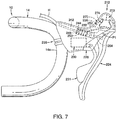
- FIG. 7 is an outside elevational view of a portion of a bicycle equipped with a bicycle hydraulic operating device in accordance with a second embodiment in which the bicycle hydraulic operating device is coupled to a drop handlebar in an installed position.
- the bicycle hydraulic operating device 12 is mounted to a drop handlebar 14 .
- the bicycle hydraulic operating device 12 is mounted to a curved section 14 a of the drop handlebar 14 .
- the bicycle hydraulic operating device 12 is particularly designed for a bicycle that is equipped with the drop handlebar 14 .
- the bicycle hydraulic operating device 12 includes both a braking function and a shifting function in a single unit.
- the shifting function could be eliminated from the bicycle hydraulic operating device 12 if needed and/or desired.
- the bicycle hydraulic operating device 12 is a bicycle hydraulic brake operating device that is specifically designed to be mounted to the curved section 14 a of the drop handlebar 14 .
- the bicycle hydraulic operating device 12 is a bicycle brake/shift device, which is also known as a bicycle brifter.
- a bicycle brifter is a device that includes both a braking function and a shifting function in a single unit that is mounted to the bicycle.
- a bicycle dropdown brifter is a device that is specifically configured to be mounted to the curved section 14 a of the drop handlebar 14 , as illustrated in FIG. 1 , and that includes both braking and shifting functions in a single unit.
- the bicycle hydraulic operating device 12 basically comprise a base member 20 , a piston 22 , an operating member 24 and a hydraulic reservoir 26 .
- the piston 22 and the operating member 24 are configured as a piston pull-type hydraulic actuator.
- the bicycle hydraulic operating device 12 further comprises a handlebar mounting structure 28 that is disposed on the base member 20 .
- the bicycle hydraulic operating device 12 further comprises a shifting unit 30 that is disposed on one of the base member 20 and the operating member 24 .
- the shifting unit 30 is disposed on the operating member 24 .
- various parts of the bicycle hydraulic operating device 12 are made of a material that makes a hydraulic fluid flow path from the hydraulic reservoir 26 to a hydraulic cylinder chamber of the piston visually perceptible to a user without special tools.
- various parts of the bicycle hydraulic operating device 12 are made of a transparent or translucent material such that the hydraulic fluid flow path is visually perceptible to a user without special tools therethrough transparent or translucent material.
- These various parts of the bicycle hydraulic operating device 12 in which the hydraulic fluid flow path is visually perceptible to a user without special tools constitute a fluid inspection portion of the bicycle hydraulic operating device 12 .
- the base member 20 includes a handlebar receiving recess 32 and a pommel portion 34 .
- the handlebar receiving recess 32 is arranged at a first end portion 36 .
- the pommel portion 34 is arranged at a second end portion 38 that is opposite to the first end portion 36 .
- the hydraulic reservoir 26 is provided on the base member 20 to form at least a part of the pommel portion 34 .
- the hydraulic reservoir 26 is provided on the second end portion 38 of the base member 20 to form at least a part of the pommel portion 34 .
- the base member 20 defines a drop handlebar bracket, which is made of a suitable rigid, hard material such as a hard plastic material (e.g., resin), a fiber reinforced plastic material (e.g., resin), a metallic material, etc.
- the base member 20 is configured to be gripped by a user.
- the base member 20 includes a grip portion 40 that is located at a middle portion of the drop handlebar bracket.
- the base member 20 essentially consists of a one-piece, unitary member.
- the base member 20 can include removable panels as needed and/or desired.
- the handlebar mounting structure 28 is attached to the base member 20 at the handlebar receiving recess 32 .
- the handlebar mounting structure 28 and the handlebar receiving recess 32 cooperate together to non-movably attach the base member 20 to the curved section 14 a of the drop handlebar 14 .
- the handlebar mounting structure 28 is a conventional handlebar clamp that is attached to the base member 20 for releasably securing the base member 20 to the curved section 14 a of the drop handlebar 14 .
- the handlebar mounting structure 28 basically includes a clamping band 28 a (i.e., a handlebar clamping member) and a first fastener part 28 b (nut) that screws unto a second fastener part 28 c (bolt) of the clamping band 28 a .
- the first and second fastener parts 28 b and 28 c are located in a hole 40 a of the grip portion 40 . In this way, in this first embodiment, the handlebar mounting structure 28 is disposed on the base member 20 .
- a head of the first fastener part 28 b applies a first force on the base member 20 and a head of the second fastener part 28 c applies a second force on the clamping band 28 a when the handlebar mounting structure 28 is tightened to secure the base member 20 to the curved section 14 a of the drop handlebar 14 .
- the clamping band 28 a is moved toward the base member 20 such that the curved section 14 a of the drop handlebar 14 is squeezed between the clamping band 28 a and the base member 20 .
- handlebar mounting structure 28 that is not limited to the illustrated clamp, but rather other suitable attachment mechanisms can be used as needed and/or desired.
- the handlebar mounting structure 28 is mounted on the base member 20 in the first embodiment.
- the bicycle hydraulic operating device 12 further comprises a cover 42 that is stretched over at least the grip portion 40 and the pommel portion 34 , which includes the hydraulic reservoir 26 , to provide a cushion to the grip portion 40 of the base member 20 and to provide an attractive appearance.
- the cover 42 is configured to at least visually cover the fluid inspection portion. Accordingly, the shape of the cover 42 depends on which parts of the bicycle hydraulic operating device 12 forms the fluid inspection portion.
- the cover 42 is removably and reattachably disposed on the base member 20 and at least overlying the fluid inspection portion. In this way, the fluid inspection portion can be easily exposed for inspecting the hydraulic fluid flow path of the bicycle hydraulic operating device 12 .
- the cover 42 is made of elastic material such as rubber. In the illustrated configuration, the cover 42 is also often referred to as a grip cover.
- the base member 20 includes a cylinder bore 44 .
- the piston 22 is movably disposed in the cylinder bore 44 .
- the piston 22 and the internal surface of the cylinder bore 44 define a hydraulic cylinder chamber.
- the cylinder bore 44 is directly formed by the base member 20 .
- the cylinder bore 44 can be formed, for example, by cutting the base member 20 or die molding of the base member 20 .
- the cylinder bore 44 is formed in a cylindrical shape. However, it will be apparent from this disclosure that an insert can be provided to the base member 20 to form the cylinder bore 44 .
- a hydraulic hose connector 46 is screwed into the base member 20 to fluidly connect a hydraulic hose H to a hydraulic fluid channel (not shown) that connects the hydraulic hose connector 46 to an outlet port 48 of the hydraulic cylinder chamber.
- the cylinder bore 44 also has an inlet port 50 that is fluidly connected to the hydraulic reservoir 26 by a fluid passage 52 .
- the hydraulic reservoir 26 is provided on the base member 20 , and is fluidly connected to the cylinder bore 44 by the fluid passage 52 .
- the operating member 24 is coupled to the piston 22 to move the piston 22 within the cylinder bore 44 .
- the piston 22 moves in the cylinder bore 44 in a reciprocal manner in response to operation of the operating member 24 .
- the piston 22 moves linearly within the cylinder bore 44 (i.e., reciprocates linearly within the cylinder bore 44 ) to force the hydraulic fluid out of the outlet port 48 of the hydraulic cylinder chamber to a brake device via the hydraulic hose H.
- the piston 22 , the operating member 24 , the hydraulic reservoir 26 and the cylinder bore 44 constitute a hydraulic brake unit.
- a biasing element 53 is provided for biasing the piston 22 to a rest position in which the hydraulic cylinder chamber has the largest volume.
- the biasing element 53 is a pair of coil torsion springs 53 a (return springs).
- the operating member 24 includes a lever 54 that is pivotally mounted relative to the base member 20 .
- the lever 54 is directly pivotally mounted to the base member 20 by a pivot pin 56 that defines a pivot axis P 1 .
- the lever 54 is an elongated operating (brake) lever that is operatively coupled to the piston 22 for performing a bicycle braking operation.
- the lever 54 is biased to a rest position with respect to the base member 20 by a biasing element 58 .
- the operating member 24 further includes an actuation cam 60 that operatively connects the piston 22 to the lever 54 .
- the biasing element 58 is operatively coupled between the lever 54 and the actuation cam 60 to bias the lever 54 and the actuation cam 60 in opposite directions about the pivot axis P 1 .
- the lever 54 is biasing against the base member 20 to establish a rest position of the operating member 24
- the actuation cam 60 is biased into engagement with a pair of rollers 62 on a connecting rod 64 that is attached to the piston 22 .
- the term “rest position” as used herein refers to a state in which the part (e.g., the operating member 24 ) remains stationary without the need of a user holding the part in that state corresponding to the rest position.
- the lever 54 moves relative to the base member 20 from the rest position along a brake operating path BA ( FIG. 3 ) to a braking position for performing a braking operation of a brake device (not shown).
- the lever 54 is provided with a pair of gearshift operating parts 66 and 68 for performing gearshifting operations of a gear changing device (not shown).
- the gearshift operating parts 66 and 68 are electrically connected to the shift unit 30 that is mounted within a recess in the base member 20 .
- the gearshift operating parts 66 and 68 are pivotally mounted on the lever 54 to pivot about a pivot axis P 2 .
- the shift unit 30 and the gearshift operating parts 66 and 68 are constructed as shown in U.S. Patent Application Publication No. 2009/0031841 A1 (assigned to Shimano, Inc.).
- the shift unit 30 is an electrical shift unit that includes a microcomputer with a processor and a pair of electrical switches (e.g. press type contact switches or a normally open contactless switches).
- the processor of the shift unit 30 can be located in the base member 20 or remotely located from the bicycle hydraulic operating device 12 if needed and/or desired. Since various electrical shifting systems such as the one illustrated herein are known in the bicycle field, shift unit 30 and the gearshift operating parts 66 and 68 will not be discussed herein for the sake of brevity.
- the hydraulic reservoir 26 is a separate part that is integrally fixed to the base member 20 .
- the hydraulic reservoir 26 provides hydraulic fluid to the hydraulic cylinder chamber that is defined by the space formed between the piston 22 and the internal surface of the cylinder bore 44 in the base member 20 .
- the hydraulic reservoir 26 is provided so that the necessary amount of hydraulic fluid can be injected from the hydraulic reservoir 26 even if the friction material (for example, a brake pad) of the braking device becomes worn.
- the amount of hydraulic fluid needed in the hydraulic cylinder chamber increase as the friction material of the braking device becomes worn.
- the hydraulic reservoir 26 prevents inconsistencies in the pressure being applied to the braking device due to swelling and contraction caused by changes in the temperature of the hydraulic fluid. Hydraulic pressure is generated through the movement of the piston 22 in response to operation of the lever 54 .
- the hydraulic reservoir 26 includes a hydraulic reservoir tank 70 , a reservoir lid 72 and a diaphragm 74 .
- the diaphragm 74 is at least partially disposed inside the hydraulic reservoir tank 70 . While the hydraulic reservoir tank 70 is illustrated as being separate from the base member 20 , it will be apparent from this disclosure that the hydraulic reservoir tank 70 can be integrally molded as one-piece unitary member with respect to the base member 20 .
- the diaphragm 74 divides the hydraulic reservoir tank 70 into an air chamber C 1 and a hydraulic fluid chamber C 2 .
- the hydraulic reservoir 26 at least partially forms the pommel portion 34 .
- the hydraulic reservoir tank 70 is made of a suitable rigid, hard material such as a hard plastic material (e.g., resin), a fiber reinforced plastic material (e.g., resin), a metallic material, etc.
- the hydraulic reservoir tank 70 and the base member 20 are made of a resin material.
- the hydraulic reservoir tank 70 is bonded to the base member 20 by using a suitable adhesive and/or heat welding.
- the hydraulic reservoir tank 70 is fixed to the base member 20 by a fastenerless joint.
- fastenerless joint as used herein means a joint between two parts that is accomplished without using mechanical fasteners, such as but not limited to rivets or bolts, screws.
- fastenerless joint will partly depend on the materials of the hydraulic reservoir tank 70 and the base member 20 .
- Some examples of fastenerless joints include adhesive bonding, pressure-sensitive tapes, soldering, ultrasonic plastic welding, ultrasonic metal welding, plastic to plastic fusing, metal to metal arc welding, and laser welding.
- the fastenerless joint can be made without a binder material, such as an adhesive or a filler, or can be made with such a binder material.
- a portion of the base member 20 is formed of a transparent or translucent material in the area of the hydraulic fluid flow path. In this way, a user can easily inspect both the cylinder bore 44 and the fluid passage 52 .
- the portion of the base member 20 that is covered by the cover 42 is made of a transparent or translucent material, while the portion of the base member 20 that is not covered by the cover 42 is not made of a transparent or translucent material.
- the portion of the base member 20 that is not covered by the cover 42 is made of an opaque material.
- the hydraulic reservoir 26 entirely is formed of a transparent or translucent material.
- the hydraulic reservoir tank 70 , the reservoir lid 72 and the diaphragm 74 are all entirely made of a transparent or translucent material. In this way, a user can easily inspect the inside of the hydraulic reservoir 26 .
- At least part of one of the base member 20 and the hydraulic reservoir 26 includes a fluid inspection portion making visually perceptible therethrough at least a portion of a hydraulic fluid flow path that includes the hydraulic reservoir 26 , the cylinder bore 44 and the fluid passage 52 .
- the fluid inspection portion is disposed on at least one of the hydraulic reservoir tank 70 , the reservoir lid 72 and the diaphragm 74 .
- the hydraulic reservoir tank 70 is fluidly connected to the cylinder bore 44 .
- the fluid passage 52 fluidly connects hydraulic reservoir tank 70 to the cylinder bore 44 .
- the hydraulic reservoir tank 70 has a tank opening 70 a and a tank body 70 b .
- the reservoir lid 72 closes the tank opening 70 a of the hydraulic reservoir tank 70 .
- the bicycle hydraulic operating device 12 preferably further comprises a bleed port 78 fluidly connected to the hydraulic fluid flow path.
- the bleed port 78 is preferably disposed on the hydraulic reservoir 26 as in the first embodiment.
- the hydraulic reservoir tank 70 includes the bleed port 78 for bleeding air from the hydraulic fluid chamber C 2 .
- the bleed port 78 can also be used for adding hydraulic fluid to the hydraulic fluid chamber C 2 instead of removing the reservoir lid 72 .
- the bleed port 78 is closed by a bleed screw 80 .
- the bleed port 78 has an internal thread for screwing the bleed screw 80 into the bleed port 78 .
- the tank opening 70 a is rectangularly shaped. Specifically, the tank opening 70 a is stepped for receiving a portion of the diaphragm 74 as discussed below.
- the upper edge of the hydraulic reservoir tank 70 has an annular groove 70 c that receives a portion of the diaphragm 74 .
- the hydraulic reservoir tank 70 has a non-uniformed shape in which the tank opening 70 a has a different cross sectional profile from a cross sectional profile of the tank body 70 b . In this way, the tank body 70 b of the hydraulic reservoir tank 70 can be made larger than the tank opening 70 a .
- the hydraulic reservoir tank 70 has an open bottom defined by a peripheral edge 70 d that is fixed to the base member 20 by the fastenerless joint.
- the hydraulic reservoir tank 70 is free of a bottom wall and is free of hidden surfaces.
- the hydraulic reservoir tank 70 has only non-hidden surfaces.
- the tank body 70 b can be integrally molded as one-piece, unitary member using straight, draw-type molds that have no undercut (hidden) surfaces, (i.e., with only non-hidden surfaces).
- hidden surface(s) refers to a surface or surfaces of a molded part which does not directly face a straight draw-type mold.
- a hidden surface or an undercut surface is a surface which faces another surface of the molded part such that a pair of straight draw-type molds cannot be used to form the hidden surface.
- draw-type injection molding refers to the use of an injection mold comprised of two halves which are separated from each other by moving each half of the mold apart from the other along a straight line to create an injection molded part without the use of mold sliders to create hidden or undercut surfaces.
- the tank opening 70 a defines an opening cross sectional area A 1 .
- the opening cross sectional area A 1 of the tank opening 70 a is defined as a minimum area in the case where the tank opening 70 a has a non-uniform shape as is the case of the first embodiment.
- the hydraulic reservoir tank 70 defines a tank cross sectional area A 2 that is parallel to the opening cross sectional area A 1 .
- the tank cross sectional area A 2 of the tank body 70 b is defined as a minimum area in the case where the tank body 70 b has a non-uniform shape as is the case of the first embodiment.
- the opening cross sectional area A 1 of the tank opening 70 a is smaller than the tank cross sectional area A 2 of the hydraulic reservoir tank 70 .
- the diaphragm 74 is a flexible, resilient member made of a suitable material such as a rubber material.
- the diaphragm 74 is a unitary, one-piece member.
- the diaphragm 74 is a bottle shaped member including a neck portion 74 a and a body portion 74 b which is larger than the neck portion 74 a .
- the hydraulic reservoir tank 70 has the bleed port 78 opening adjacent to a neck area of the hydraulic fluid chamber C 2 that is defined by the neck portion 74 a of the diaphragm 74 .
- the body portion 74 b of the diaphragm 74 has a cross sectional area A 3 that is parallel to the opening cross sectional area. A 1 .
- the cross sectional area A 3 of the body portion 74 b of the diaphragm 74 is defined as a maximum area in the case where the body portion 74 b of the diaphragm 74 has a non-uniform shape as is the case of the first embodiment.
- the cross sectional area A 3 of the body portion 74 b of the diaphragm 74 is larger than the opening cross sectional area.
- a 1 of the tank opening 70 a is .
- the neck portion 74 a has a diaphragm opening 74 c which is arranged opposite to the body portion 74 b .
- the neck portion 74 a is fixed on the tank opening 70 a .
- the neck portion 74 a has a peripheral mounting flange 74 c that extends annularly outwards.
- the annular groove 70 c in the upper edge of the hydraulic reservoir tank 70 receives the peripheral mounting flange 74 c of the diaphragm 74 .
- the peripheral mounting flange 74 c of the diaphragm 74 is sandwiched between the reservoir lid 72 and the upper edge of the hydraulic reservoir tank 70 .
- the reservoir lid 72 is frictionally retained in the tank opening 70 a of the hydraulic reservoir tank 70 by slightly compressing the diaphragm 74 . As a result, a seal is created by the diaphragm 74 between the hydraulic reservoir tank 70 and the reservoir lid 72 .
- the reservoir lid 72 has an air passageway 72 a connecting the air chamber C 1 to outside of the base member 20 .
- the reservoir lid 72 is made of a resin material.
- the bicycle hydraulic operating device 212 basically comprises a base member 220 , a piston 222 , an operating member 224 and a hydraulic reservoir 226 .
- the bicycle hydraulic operating device 212 further comprises a handlebar mounting structure 228 that is disposed on the base member 220 .
- the bicycle hydraulic operating device 212 further comprises a shifting unit 230 that is disposed on the base member 220 .
- the bicycle hydraulic operating device 212 further comprises a cover 242 .
- the hydraulic reservoir 226 is fluidly connected to a cylinder bore 244 that is formed in the base member 220 .
- the hydraulic reservoir 226 is identical to the hydraulic reservoir 26 .
- the cylinder bore 244 has an outlet port 248 that is fluidly connected to the hose H. Also, a fluid passage 252 extends between the hydraulic reservoir 226 and the cylinder bore 244 for supplying hydraulic fluid from the hydraulic reservoir 226 to the cylinder bore 244 .
- the hydraulic reservoir 226 includes a hydraulic reservoir tank 270 , a reservoir lid 272 and a diaphragm 274 .
- the shifting unit 230 is a mechanical shifting unit that basically has the same structure and operates in the same way as the so called holding mechanism that is disclosed in U.S. Pat. No. 7,779,718. However, the shifting unit 230 has been configured to be supported by the base member 220 and operated by a control cable (e.g., Bowman cable). In other words, the shifting unit 230 is operated by a control lever 231 in the same manner as the control lever for the so called holding mechanism that is disclosed in U.S. Pat. No. 7,779,718. Since the structure and operations of the shifting unit 230 are well known to those skilled in the bicycle field, the structure and operations of the shifting unit 230 will not be discussed in detail herein.
- a control cable e.g., Bowman cable
- the piston 222 and the operating member 224 are configured as a piston push-type hydraulic actuator.
- a biasing element 253 is provided for biasing the piston 222 to a rest position in which the hydraulic cylinder chamber has the largest volume.
- the biasing element 253 is a compression spring.
- the biasing element 253 is also used to biasing the operating member 224 to a rest position.
- the piston 222 is operatively coupled to the operating member 224 by a connecting rod 264 .
- the connecting rod 264 has a first end pivotally coupled to the piston 222 and a second end pivotally coupled to the operating member 224 .
- the operating member 224 is pivotally mounted on the base member 220 to pivot about the pivot axis P 1 such that operation of the operating member 224 from the rest position to an operated position about the pivot axis P 1 causes the piston 222 to be pushed inside of the cylinder bore 244 .
- hydraulic fluid is forced out of the cylinder bore 244 via the outlet port 248 to the brake device (not shown). Since the piston push-type hydraulic actuators are known in the bicycle field, the piston push-type hydraulic actuator of the bicycle hydraulic operating device 212 will not be discussed or illustrated in detail herein.
- the term “comprising” and its derivatives, as used herein, are intended to be open ended terms that specify the presence of the stated features, elements, components, groups, integers, and/or steps, but do not exclude the presence of other unstated features, elements, components, groups, integers and/or steps.
- the foregoing also applies to words having similar meanings such as the terms, “including”, “having” and their derivatives.
- the terms “part,” “section,” “portion,” “member” or “element” when used in the singular can have the dual meaning of a single part or a plurality of parts unless otherwise stated.
- the following directional terms “frame facing side”, “non-frame facing side”, “forward”, “rearward”, “front”, “rear”, “up”, “down”, “above”, “below”, “upward”, “downward”, “top”, “bottom”, “side”, “vertical”, “horizontal”, “perpendicular” and “transverse” as well as any other similar directional terms refer to those directions of a bicycle in an upright, riding position and equipped with the bicycle hydraulic operating device. Accordingly, these directional terms, as utilized to describe the bicycle hydraulic operating device should be interpreted relative to a bicycle in an upright riding position on a horizontal surface and that is equipped with the bicycle hydraulic operating device.
- the terms “left” and “right” are used to indicate the “right” when referencing from the right side as viewed from the rear of the bicycle, and the “left” when referencing from the left side as viewed from the rear of the bicycle.
- first and second may be used herein to describe various components these components should not be limited by these terms. These terms are only used to distinguish one component from another. Thus, for example, a first component discussed above could be termed a second component and vice versa without departing from the teachings of the present invention.
- the term “attached” or “attaching”, as used herein, encompasses configurations in which an element is directly secured to another element by affixing the element directly to the other element; configurations in which the element is indirectly secured to the other element by affixing the element to the intermediate member(s) which in turn are affixed to the other element; and configurations in which one element is integral with another element, i.e.
Landscapes
- Engineering & Computer Science (AREA)
- Mechanical Engineering (AREA)
- Transportation (AREA)
- Physics & Mathematics (AREA)
- Fluid Mechanics (AREA)
- Chemical & Material Sciences (AREA)
- Combustion & Propulsion (AREA)
- Transmission Of Braking Force In Braking Systems (AREA)
- Mechanical Control Devices (AREA)
- Valves And Accessory Devices For Braking Systems (AREA)
Abstract
Description
-
- Referring initially to
FIGS. 1 and 2 , abicycle 10 is illustrated that is equipped with a bicyclehydraulic operating device 12 in accordance with a first embodiment. The bicyclehydraulic operating device 12 is a right hand side control device operated by the rider's right hand to operate a first brake device (not shown) and a first gear shifting device (not shown, e.g., an electric rear derailleur). It will be apparent to those skilled in the bicycle field that the configuration of the bicyclehydraulic operating device 12 can be adapted to a left hand side control device that is operated by the rider's left hand.
- Referring initially to
Claims (16)
Priority Applications (4)
| Application Number | Priority Date | Filing Date | Title |
|---|---|---|---|
| DE102017206712.8A DE102017206712A1 (en) | 2016-06-16 | 2017-04-21 | Hydraulic bicycle actuator |
| CN201710456272.6A CN107521605A (en) | 2016-06-16 | 2017-06-16 | Bicycle hydraulic operation device |
| TW106120117A TWI679146B (en) | 2016-06-16 | 2017-06-16 | Bicycle hydraulic operating device |
| US15/184,948 US10668907B2 (en) | 2016-06-16 | 2018-06-16 | Bicycle hydraulic operating device |
Applications Claiming Priority (1)
| Application Number | Priority Date | Filing Date | Title |
|---|---|---|---|
| US15/184,948 US10668907B2 (en) | 2016-06-16 | 2018-06-16 | Bicycle hydraulic operating device |
Publications (2)
| Publication Number | Publication Date |
|---|---|
| US20170361819A1 US20170361819A1 (en) | 2017-12-21 |
| US10668907B2 true US10668907B2 (en) | 2020-06-02 |
Family
ID=60481221
Family Applications (1)
| Application Number | Title | Priority Date | Filing Date |
|---|---|---|---|
| US15/184,948 Active 2039-02-10 US10668907B2 (en) | 2016-06-16 | 2018-06-16 | Bicycle hydraulic operating device |
Country Status (4)
| Country | Link |
|---|---|
| US (1) | US10668907B2 (en) |
| CN (1) | CN107521605A (en) |
| DE (1) | DE102017206712A1 (en) |
| TW (1) | TWI679146B (en) |
Families Citing this family (2)
| Publication number | Priority date | Publication date | Assignee | Title |
|---|---|---|---|---|
| DE102018118460A1 (en) * | 2018-07-31 | 2020-02-06 | Shimano Inc. | HYDRAULIC DEVICE |
| TWI776223B (en) * | 2019-09-16 | 2022-09-01 | 美商速聯有限責任公司 | Hydraulic bicycle control device |
Citations (9)
| Publication number | Priority date | Publication date | Assignee | Title |
|---|---|---|---|---|
| US20030121736A1 (en) | 2001-12-28 | 2003-07-03 | Avid, L.L.C. | Master cylinder lever for a hydraulic disc brake having a backpack reservoir |
| US20070215417A1 (en) * | 2006-03-14 | 2007-09-20 | Jui-Pin Chen | Bicycle brake lever |
| US20090031841A1 (en) | 2007-07-30 | 2009-02-05 | Shimano Inc. | Bicycle control device |
| US7779718B2 (en) | 2005-03-03 | 2010-08-24 | Sram, Llc | Bicycle shifter |
| US8448762B2 (en) | 2010-03-30 | 2013-05-28 | Shimano Inc. | Hydraulic brake lever apparatus |
| US8905205B2 (en) | 2012-12-26 | 2014-12-09 | Shimano Inc. | Bicycle hydraulic component operating device |
| US20150001018A1 (en) * | 2013-06-28 | 2015-01-01 | Shimano Inc. | Bicycle hydraulic operating device |
| US20150090112A1 (en) | 2013-10-01 | 2015-04-02 | Shimano Inc. | Bicycle hydraulic operating device |
| US9290232B2 (en) | 2014-03-24 | 2016-03-22 | Sram, Llc | Variable rate assembly for a brake system for bicycle |
Family Cites Families (5)
| Publication number | Priority date | Publication date | Assignee | Title |
|---|---|---|---|---|
| IT1245445B (en) * | 1991-03-11 | 1994-09-20 | Campagnolo Srl | TRANSMISSION AND BRAKE CONTROL UNIT FOR A BICYCLE |
| JP2009202783A (en) * | 2008-02-28 | 2009-09-10 | Showa Corp | Rear portion hydraulic shock absorber for bicycle |
| US9090303B2 (en) * | 2012-05-18 | 2015-07-28 | Shimano Inc. | Bicycle control device |
| US10053181B2 (en) * | 2012-05-30 | 2018-08-21 | Shimano Inc. | Bicycle shift operating device |
| JP3182210U (en) * | 2012-12-26 | 2013-03-14 | 株式会社シマノ | Bicycle control device |
-
2017
- 2017-04-21 DE DE102017206712.8A patent/DE102017206712A1/en active Pending
- 2017-06-16 TW TW106120117A patent/TWI679146B/en active
- 2017-06-16 CN CN201710456272.6A patent/CN107521605A/en active Pending
-
2018
- 2018-06-16 US US15/184,948 patent/US10668907B2/en active Active
Patent Citations (9)
| Publication number | Priority date | Publication date | Assignee | Title |
|---|---|---|---|---|
| US20030121736A1 (en) | 2001-12-28 | 2003-07-03 | Avid, L.L.C. | Master cylinder lever for a hydraulic disc brake having a backpack reservoir |
| US7779718B2 (en) | 2005-03-03 | 2010-08-24 | Sram, Llc | Bicycle shifter |
| US20070215417A1 (en) * | 2006-03-14 | 2007-09-20 | Jui-Pin Chen | Bicycle brake lever |
| US20090031841A1 (en) | 2007-07-30 | 2009-02-05 | Shimano Inc. | Bicycle control device |
| US8448762B2 (en) | 2010-03-30 | 2013-05-28 | Shimano Inc. | Hydraulic brake lever apparatus |
| US8905205B2 (en) | 2012-12-26 | 2014-12-09 | Shimano Inc. | Bicycle hydraulic component operating device |
| US20150001018A1 (en) * | 2013-06-28 | 2015-01-01 | Shimano Inc. | Bicycle hydraulic operating device |
| US20150090112A1 (en) | 2013-10-01 | 2015-04-02 | Shimano Inc. | Bicycle hydraulic operating device |
| US9290232B2 (en) | 2014-03-24 | 2016-03-22 | Sram, Llc | Variable rate assembly for a brake system for bicycle |
Also Published As
| Publication number | Publication date |
|---|---|
| TW201800297A (en) | 2018-01-01 |
| TWI679146B (en) | 2019-12-11 |
| CN107521605A (en) | 2017-12-29 |
| DE102017206712A1 (en) | 2017-12-21 |
| US20170361819A1 (en) | 2017-12-21 |
Similar Documents
| Publication | Publication Date | Title |
|---|---|---|
| US9937978B2 (en) | Bicycle hydraulic operating device | |
| US10232905B2 (en) | Bicycle hydraulic operating device | |
| US8905205B2 (en) | Bicycle hydraulic component operating device | |
| US10940913B2 (en) | Bicycle hydraulic operating system | |
| US9321505B2 (en) | Bicycle hydraulic component operating device | |
| US9365260B2 (en) | Bicycle hydraulic operating device | |
| US9415831B2 (en) | Bicycle hydraulic operating device | |
| US10407122B2 (en) | Bicycle operating device | |
| US11203394B2 (en) | Bicycle hydraulic device | |
| US9688348B2 (en) | Hydraulic hose fitting and hydraulic device | |
| US10668907B2 (en) | Bicycle hydraulic operating device | |
| CN109305279B (en) | Hydraulic operating system | |
| US10189540B2 (en) | Bicycle hydraulic operating device | |
| US10118666B2 (en) | Bicycle hydraulic device | |
| US10384741B2 (en) | Bicycle hydraulic operating device | |
| US10343744B2 (en) | Bicycle operating device |
Legal Events
| Date | Code | Title | Description |
|---|---|---|---|
| AS | Assignment |
Owner name: SHIMANO INC., JAPAN Free format text: ASSIGNMENT OF ASSIGNORS INTEREST;ASSIGNORS:MIKI, YOSHIMITSU;KOSAKA, KENTARO;MATSUEDA, KEIJI;REEL/FRAME:038937/0639 Effective date: 20160616 |
|
| STPP | Information on status: patent application and granting procedure in general |
Free format text: NON FINAL ACTION MAILED |
|
| STPP | Information on status: patent application and granting procedure in general |
Free format text: RESPONSE TO NON-FINAL OFFICE ACTION ENTERED AND FORWARDED TO EXAMINER |
|
| STPP | Information on status: patent application and granting procedure in general |
Free format text: FINAL REJECTION MAILED |
|
| STPP | Information on status: patent application and granting procedure in general |
Free format text: DOCKETED NEW CASE - READY FOR EXAMINATION |
|
| STPP | Information on status: patent application and granting procedure in general |
Free format text: NON FINAL ACTION MAILED |
|
| STPP | Information on status: patent application and granting procedure in general |
Free format text: RESPONSE TO NON-FINAL OFFICE ACTION ENTERED AND FORWARDED TO EXAMINER |
|
| STPP | Information on status: patent application and granting procedure in general |
Free format text: PUBLICATIONS -- ISSUE FEE PAYMENT RECEIVED |
|
| STCF | Information on status: patent grant |
Free format text: PATENTED CASE |
|
| CC | Certificate of correction | ||
| MAFP | Maintenance fee payment |
Free format text: PAYMENT OF MAINTENANCE FEE, 4TH YEAR, LARGE ENTITY (ORIGINAL EVENT CODE: M1551); ENTITY STATUS OF PATENT OWNER: LARGE ENTITY Year of fee payment: 4 |