US10668358B2 - Skate for a hockey goalkeeper - Google Patents
Skate for a hockey goalkeeper Download PDFInfo
- Publication number
- US10668358B2 US10668358B2 US15/270,756 US201615270756A US10668358B2 US 10668358 B2 US10668358 B2 US 10668358B2 US 201615270756 A US201615270756 A US 201615270756A US 10668358 B2 US10668358 B2 US 10668358B2
- Authority
- US
- United States
- Prior art keywords
- skate
- outer shell
- side portion
- lateral side
- toe cap
- Prior art date
- Legal status (The legal status is an assumption and is not a legal conclusion. Google has not performed a legal analysis and makes no representation as to the accuracy of the status listed.)
- Active
Links
- 210000003371 toe Anatomy 0.000 claims description 174
- 239000000463 material Substances 0.000 claims description 91
- 210000002683 foot Anatomy 0.000 claims description 75
- 210000003423 ankle Anatomy 0.000 claims description 50
- 230000002787 reinforcement Effects 0.000 claims description 18
- -1 polypropylene Polymers 0.000 claims description 15
- 239000000835 fiber Substances 0.000 claims description 14
- 239000002131 composite material Substances 0.000 claims description 12
- 230000007246 mechanism Effects 0.000 claims description 11
- 239000011159 matrix material Substances 0.000 claims description 8
- 229920001778 nylon Polymers 0.000 claims description 8
- 239000004677 Nylon Substances 0.000 claims description 7
- 239000004743 Polypropylene Substances 0.000 claims description 7
- 229920001155 polypropylene Polymers 0.000 claims description 7
- 229920005989 resin Polymers 0.000 claims description 7
- 239000011347 resin Substances 0.000 claims description 7
- 210000001361 achilles tendon Anatomy 0.000 claims description 5
- 210000001255 hallux Anatomy 0.000 claims description 5
- 229920000728 polyester Polymers 0.000 claims description 4
- 229920000915 polyvinyl chloride Polymers 0.000 claims description 4
- 239000004800 polyvinyl chloride Substances 0.000 claims description 4
- 230000003014 reinforcing effect Effects 0.000 claims description 3
- 229920000554 ionomer Polymers 0.000 claims description 2
- 229920003048 styrene butadiene rubber Polymers 0.000 claims description 2
- 210000002435 tendon Anatomy 0.000 claims description 2
- 229920002994 synthetic fiber Polymers 0.000 abstract description 70
- 239000000853 adhesive Substances 0.000 description 10
- 230000001070 adhesive effect Effects 0.000 description 10
- 230000002093 peripheral effect Effects 0.000 description 8
- 238000012360 testing method Methods 0.000 description 8
- 229920001169 thermoplastic Polymers 0.000 description 8
- 239000004416 thermosoftening plastic Substances 0.000 description 8
- 238000005452 bending Methods 0.000 description 7
- 229920001187 thermosetting polymer Polymers 0.000 description 7
- 229920002635 polyurethane Polymers 0.000 description 6
- 239000004814 polyurethane Substances 0.000 description 6
- 239000006260 foam Substances 0.000 description 5
- 229920000049 Carbon (fiber) Polymers 0.000 description 4
- 239000004698 Polyethylene Substances 0.000 description 4
- 239000004917 carbon fiber Substances 0.000 description 4
- 238000000465 moulding Methods 0.000 description 4
- 238000013001 point bending Methods 0.000 description 4
- 239000004417 polycarbonate Substances 0.000 description 4
- 229920000515 polycarbonate Polymers 0.000 description 4
- 229920000573 polyethylene Polymers 0.000 description 4
- 229920000642 polymer Polymers 0.000 description 4
- 230000001681 protective effect Effects 0.000 description 4
- 239000004593 Epoxy Substances 0.000 description 3
- 210000004744 fore-foot Anatomy 0.000 description 3
- 210000000548 hind-foot Anatomy 0.000 description 3
- 239000011796 hollow space material Substances 0.000 description 3
- 238000000034 method Methods 0.000 description 3
- 230000007935 neutral effect Effects 0.000 description 3
- 230000008569 process Effects 0.000 description 3
- 230000000717 retained effect Effects 0.000 description 3
- 229920000178 Acrylic resin Polymers 0.000 description 2
- 239000004925 Acrylic resin Substances 0.000 description 2
- ZOXJGFHDIHLPTG-UHFFFAOYSA-N Boron Chemical compound [B] ZOXJGFHDIHLPTG-UHFFFAOYSA-N 0.000 description 2
- 239000004696 Poly ether ether ketone Substances 0.000 description 2
- 239000004962 Polyamide-imide Substances 0.000 description 2
- 239000004642 Polyimide Substances 0.000 description 2
- 229920000265 Polyparaphenylene Polymers 0.000 description 2
- QYKIQEUNHZKYBP-UHFFFAOYSA-N Vinyl ether Chemical compound C=COC=C QYKIQEUNHZKYBP-UHFFFAOYSA-N 0.000 description 2
- XECAHXYUAAWDEL-UHFFFAOYSA-N acrylonitrile butadiene styrene Chemical compound C=CC=C.C=CC#N.C=CC1=CC=CC=C1 XECAHXYUAAWDEL-UHFFFAOYSA-N 0.000 description 2
- 239000004676 acrylonitrile butadiene styrene Substances 0.000 description 2
- 229920000122 acrylonitrile butadiene styrene Polymers 0.000 description 2
- 239000004760 aramid Substances 0.000 description 2
- 229920006231 aramid fiber Polymers 0.000 description 2
- 229910052796 boron Inorganic materials 0.000 description 2
- 239000000919 ceramic Substances 0.000 description 2
- 239000004643 cyanate ester Substances 0.000 description 2
- 239000004744 fabric Substances 0.000 description 2
- 239000003365 glass fiber Substances 0.000 description 2
- 229920001903 high density polyethylene Polymers 0.000 description 2
- 239000004700 high-density polyethylene Substances 0.000 description 2
- 210000000452 mid-foot Anatomy 0.000 description 2
- 239000000203 mixture Substances 0.000 description 2
- 229920003229 poly(methyl methacrylate) Polymers 0.000 description 2
- 229920002492 poly(sulfone) Polymers 0.000 description 2
- 229920002312 polyamide-imide Polymers 0.000 description 2
- 229920002530 polyetherether ketone Polymers 0.000 description 2
- 229920000139 polyethylene terephthalate Polymers 0.000 description 2
- 239000005020 polyethylene terephthalate Substances 0.000 description 2
- 229920001721 polyimide Polymers 0.000 description 2
- 239000002952 polymeric resin Substances 0.000 description 2
- 239000004926 polymethyl methacrylate Substances 0.000 description 2
- 229920003002 synthetic resin Polymers 0.000 description 2
- 229920001567 vinyl ester resin Polymers 0.000 description 2
- 239000011800 void material Substances 0.000 description 2
- 229920004142 LEXAN™ Polymers 0.000 description 1
- 229920003182 Surlyn® Polymers 0.000 description 1
- 239000005035 Surlyn® Substances 0.000 description 1
- 238000004026 adhesive bonding Methods 0.000 description 1
- 230000008901 benefit Effects 0.000 description 1
- 210000000988 bone and bone Anatomy 0.000 description 1
- 230000003247 decreasing effect Effects 0.000 description 1
- 238000013461 design Methods 0.000 description 1
- 239000005038 ethylene vinyl acetate Substances 0.000 description 1
- 239000011152 fibreglass Substances 0.000 description 1
- 239000002657 fibrous material Substances 0.000 description 1
- 239000006261 foam material Substances 0.000 description 1
- 238000002347 injection Methods 0.000 description 1
- 239000007924 injection Substances 0.000 description 1
- 239000002648 laminated material Substances 0.000 description 1
- 239000007769 metal material Substances 0.000 description 1
- VNWKTOKETHGBQD-UHFFFAOYSA-N methane Chemical compound C VNWKTOKETHGBQD-UHFFFAOYSA-N 0.000 description 1
- 238000012986 modification Methods 0.000 description 1
- 230000004048 modification Effects 0.000 description 1
- 229920003023 plastic Polymers 0.000 description 1
- 239000004033 plastic Substances 0.000 description 1
- 229920013657 polymer matrix composite Polymers 0.000 description 1
- 239000011160 polymer matrix composite Substances 0.000 description 1
- 230000009467 reduction Effects 0.000 description 1
- 238000012552 review Methods 0.000 description 1
- 239000007779 soft material Substances 0.000 description 1
- 229910001220 stainless steel Inorganic materials 0.000 description 1
- 239000010935 stainless steel Substances 0.000 description 1
- 239000004753 textile Substances 0.000 description 1
- 239000012815 thermoplastic material Substances 0.000 description 1
- 125000000391 vinyl group Chemical group [H]C([*])=C([H])[H] 0.000 description 1
- 229920002554 vinyl polymer Polymers 0.000 description 1
Images


Classifications
-
- A—HUMAN NECESSITIES
- A43—FOOTWEAR
- A43B—CHARACTERISTIC FEATURES OF FOOTWEAR; PARTS OF FOOTWEAR
- A43B5/00—Footwear for sporting purposes
- A43B5/16—Skating boots
- A43B5/1666—Skating boots characterised by the upper
- A43B5/1691—Skating boots characterised by the upper characterised by the higher part of the upper, e.g. surrounding the ankle, by the quarter or cuff
-
- A—HUMAN NECESSITIES
- A63—SPORTS; GAMES; AMUSEMENTS
- A63C—SKATES; SKIS; ROLLER SKATES; DESIGN OR LAYOUT OF COURTS, RINKS OR THE LIKE
- A63C1/00—Skates
- A63C1/30—Skates with special blades
- A63C1/303—Skates with special blades removably fastened to the blade holder
-
- A—HUMAN NECESSITIES
- A43—FOOTWEAR
- A43B—CHARACTERISTIC FEATURES OF FOOTWEAR; PARTS OF FOOTWEAR
- A43B5/00—Footwear for sporting purposes
- A43B5/16—Skating boots
- A43B5/1625—Skating boots made from materials with different rigidities
-
- A—HUMAN NECESSITIES
- A43—FOOTWEAR
- A43B—CHARACTERISTIC FEATURES OF FOOTWEAR; PARTS OF FOOTWEAR
- A43B5/00—Footwear for sporting purposes
- A43B5/16—Skating boots
- A43B5/1666—Skating boots characterised by the upper
- A43B5/1683—Skating boots characterised by the upper characterised by the lower part of the upper or by the shell
-
- A—HUMAN NECESSITIES
- A63—SPORTS; GAMES; AMUSEMENTS
- A63C—SKATES; SKIS; ROLLER SKATES; DESIGN OR LAYOUT OF COURTS, RINKS OR THE LIKE
- A63C1/00—Skates
Definitions
- the invention generally relates to equipment for hockey goalkeepers and, more particularly, to skates for hockey goalkeepers.
- Hockey goalkeepers (a.k.a. goalies) defend their team's goal in a hockey game.
- a hockey goalie wears various equipment, including goalie skates to move on a playing surface (e.g., ice), leg pads to protect his/her legs when used to stop a puck or ball and/or when moving (e.g., dropping) them onto the playing surface, and a blocker and a catcher to stop the puck or ball with his/her arms and hands
- a playing surface e.g., ice
- leg pads to protect his/her legs when used to stop a puck or ball and/or when moving (e.g., dropping) them onto the playing surface
- a blocker and a catcher to stop the puck or ball with his/her arms and hands
- a goalie skate typically comprises a skate boot for receiving a goalie's foot and a cowling that covers toe, heel, lower medial, and lower lateral areas of the skate boot.
- the cowling is a hard cover that extends over the toe, heel, lower medial, and lower lateral areas of the skate boot for added protection in those areas.
- the cowling also carries a blade or set of inline wheels of the skate that engages the playing surface.
- cowling imparts impact protection to the goalie skate, it may detrimentally affect other characteristics of the skate. For instance, a maximal angle of attack of the goalie skate with the playing surface may be limited by the cowling as a medial side of the cowling will contact the playing surface first when the goalie skate is inclined. This can in turn affect how fast and how hard the goalie can push off the playing surface during play.
- a goalie skate for a hockey goalkeeper.
- the goalie skate comprises a skate boot for receiving a foot of the hockey goalkeeper, a blade for contacting ice, and a blade holder between the skate boot and the blade.
- the skate boot comprises an outer shell comprising a synthetic material.
- the goalie skate is cowlingless.
- a goalie skate for a hockey goalkeeper.
- the goalie skate comprises a skate boot for receiving a foot of the hockey goalkeeper.
- the skate boot comprises an outer shell comprising a synthetic material.
- the outer shell comprises a lateral side portion for facing a lateral side of the foot of the hockey goalkeeper, a medial side portion for facing a medial side of the foot of the hockey goalkeeper, and a heel portion for facing a heel of the foot of the hockey goalkeeper.
- the goalie skate further comprises a blade for contacting ice and a blade holder between the skate boot and the blade. A bottom region of the lateral side portion of the outer shell, a bottom region of the medial side portion of the outer shell, and a bottom region of the heel portion of the outer shell are exposed.
- a goalie skate for a hockey goalkeeper.
- the goalie skate comprises a skate boot for receiving a foot of the hockey goalkeeper.
- the skate boot comprises an outer shell comprising a synthetic material.
- the goalie skate further comprises a blade for contacting ice and a blade holder between the skate boot and the blade.
- the blade holder comprises a blade-detachment mechanism configured to selectively detach and remove the blade from the blade holder and attach the blade to the blade holder.
- the blade-detachment mechanism comprises an actuator manually operable to detach and remove the blade from the blade holder.
- a goalie skate for a hockey goalkeeper.
- the goalie skate comprises a skate boot for receiving a foot of the hockey goalkeeper, a skating device for contacting a playing surface, and a holder between the skate boot and the skating device.
- the skate boot comprises an outer shell comprising a synthetic material.
- the goalie skate is cowlingless.
- FIG. 1 is an example of a hockey goalkeeper (i.e., goalie) wearing a goalie skate in accordance with an embodiment of the invention
- FIGS. 2 and 3 show perspective views of the goalie skate
- FIGS. 4 to 6 show a side view, a rear view and a top view of the goalie skate
- FIGS. 7 and 8 show lateral and medial side views of a typical goalie skate comprising a cowling
- FIG. 9 shows a rear view of the goalie skate when the goalie skate engages a playing surface at a maximal attack angle
- FIG. 10 shows a side view of a skate boot of the goalie skate
- FIG. 11 shows an exploded view of the skate boot of the goalie skate, including an outer shell, a tongue, a toe cap, and an inner lining of the skate boot;
- FIG. 12 shows a perspective view of the outer shell of the skate boot including a body and an overlay of the outer shell
- FIG. 13 shows a closeup view of part of a lateral side portion of the outer shell including the overlay
- FIGS. 14A and 14B show a cross-sectional view of the outer shell taken along lines 14 A- 14 A and 14 B- 14 B respectively, as indicated in FIG. 13 ;
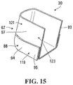
- FIG. 15 shows a perspective view of a heel portion of the outer shell
- FIGS. 16 and 17 show perspective views of the toe cap of the skate boot
- FIG. 18 shows a side view of the toe cap
- FIG. 19 shows a cross-sectional view of the toe cap taken along line 19 - 19 as indicated in FIG. 18 ;
- FIG. 20 shows a cross-sectional view of the toe cap where the toe cap comprises areas of increased thickness
- FIGS. 21 to 23 show a reinforcement of the toe cap in accordance with various embodiments
- FIGS. 24 and 25 show a perspective view and an exploded of the tongue of the skate boot
- FIG. 26 shows a blade and a blade holder of the goalie skate
- FIGS. 27 and 28 show a top view and a bottom view of the blade holder, including a blade-detachment mechanism
- FIG. 29 shows a side view of the blade
- FIGS. 30 to 33 show variants in which the blade is permanently affixed to the blade holder
- FIGS. 34 and 35 show a side view and front view of the blade in accordance with a variant in which in the blade comprises a runner and a body;
- FIG. 36 shows a three-point bending test being performed on a part of the outer shell of the skate boot to determine a stiffness of the outer shell
- FIG. 37 shows a perspective view of a portion of the outer shell, including its lateral and medial side portions, in accordance with a variant in which a first area of the lateral side portion is stiffer than a second area of the lateral side portion;
- FIG. 38 shows a perspective view of a heel portion of the outer shell in accordance with a variant in which a first area of the heel portion is stiffer than a second area of the heel portion;
- FIG. 39 shows a perspective view of the toe cap in accordance with a variant in which a first area of a lateral side portion of the toe cap is stiffer than a second area of the lateral side portion of the toe cap;
- FIG. 40 shows a perspective view of the toe cap in accordance with a variant in which the toe cap comprises a first synthetic material and a second synthetic material;
- FIG. 41 shows a perspective view of the toe cap in accordance with a variant in which the toe cap comprises an overlay comprising the second synthetic material;
- FIGS. 42 and 43 are side and front views of a right foot of the goalie with an integument of the foot shown in dotted lines and bones shown in solid lines.
- FIGS. 1 to 6 show an example of skates 10 1 , 10 2 for a hockey goalkeeper 12 in accordance with an embodiment of the invention.
- the hockey goalkeeper 12 who will be referred to as a “goalie”, defends his/her team's goal in a game of hockey played on a playing surface 14 .
- the skates 10 1 , 10 2 are worn by the goalie 12 to move on the playing surface 14 for goalkeeping.
- the goalie 12 also wears other equipment for goalkeeping, including, in this embodiment, leg pads 16 1 , 16 2 to protect his/her legs when used to stop a projectile, i.e., a puck or ball, during play and/or when moving (e.g., dropping) them onto the playing surface 14 , as well as a blocker 18 and a catcher 20 to stop the puck or ball with his/her arms and hands.
- a type of hockey played is ice hockey such that the playing surface 14 is ice and the skates 10 1 , 10 2 are goalie skates.
- the skates 10 1 , 10 2 are designed specifically for goalkeeping by the goalie 12 , as opposed to other skates for hockey players other than goalies (i.e., forwards and defensemen), and can thus be referred to as “goalie skates”.
- Each skate 10 X comprises a skate boot 22 for receiving a foot 11 of the goalie 12 , a blade 26 for contacting the ice 14 , and a blade holder 24 between the skate boot 22 and the blade 26 .
- the skate 10 X has a longitudinal direction, a widthwise direction, and a height-wise direction.
- the skate 10 X is constructed to help enhance performance of the goalie 12 , including, for example, by being lighter and facilitating pushing (e.g., quicker and harder pushes) against the ice 14 , which may improve mobility on the ice 14 .
- the skate 10 X also facilitates removal of the blade 26 , such as to replace the blade 26 with another blade or to sharpen or perform another operation on the blade 26 before installing it back into the skate 10 X .
- this is achieved by the skate 10 X being cowlingless, i.e., being free of (i.e., without) any cowling (i.e., hard cover) covering a toe area 31 , a heel area 33 , a lower medial area 35 , and a lower lateral area 37 of the skate boot 22 .
- This is in contrast to a conventional skate 510 for a hockey goalie, as shown in FIGS. 7 and 8 , which comprises a cowling 515 covering a toe area 531 , a heel area 533 , a lower medial area 535 , and a lower lateral area 537 of a skate boot 522 .
- the skate 10 X supports the goalie's foot 11 relatively high relative to the ice 14 .
- a support height H S of the skate 10 X which refers to a height from a bottom 50 of the blade 26 to a bottom 52 of the skate boot 22 , may be relatively large.
- a ratio H S /H of the support height H S of the skate 10 X over an overall height H of the skate 10 X may be at least 0.25, in some cases 0.275, in some cases at least 0.30, in some cases at least 0.325, in some cases at least 0.35, and in some cases even more.
- the ratio of the support height H S of the skate 10 X over the overall height H of the skate 10 X may have any other value in other embodiments.
- the support height H S of the skate 10 X may be at least 70 mm, in some cases at least 75 mm, in some cases at least 80 mm, in some cases at least 85 mm, and in some cases even more.
- the support height H S of the skate 10 X may have any other value in other embodiments.
- the skate 10 X allows an angle of attack ⁇ A with the ice 14 that can be larger (e.g., greater than for conventional hockey goalkeeper skates with cowlings).
- the angle of attack ⁇ A of the skate 10 , with the ice 14 refers to an angle between the ice 14 and a plane 49 of the blade 26 when the skate 10 , is inclined relative to the ice 10 such that a medial surface of the skate 10 X touches the ice 14 . Allowing the angle of attack ⁇ A of the skate 10 X with the ice 14 to be larger may help the goalie 12 to execute quicker and harder pushes against the ice 14 .
- the angle of attack ⁇ A of the skate 10 X with the ice 14 may be at least 140°, in some cases at least 142°, in some cases at least 145°, in some cases at least 148°, in some cases at least 150°, and in some cases even more.
- the angle of attack ⁇ A of the skate 10 X with the ice 14 may have any other value in other embodiments.
- the skate boot 22 defines a cavity 54 for receiving the goalie's foot 11 .
- the goalie's foot 11 includes toes T, a ball B, an arch ARC, a plantar surface PS, a top surface TS, a medial side MS, and a lateral side LS.
- the top surface TS of the goalie's foot 11 is continuous with a lower portion of a shin S of the goalie 12 .
- the goalie 12 has a heel HL, an Achilles tendon AT, and an ankle A having a medial malleolus MM and a lateral malleolus LM that is at a lower position than the medial malleolus MM.
- the Achilles tendon AT has an upper part UP and a lower part LP projecting outwardly with relation to the upper part UP and merging with the heel HL.
- a forefoot of the goalie 12 includes the toes T and the ball B, a hindfoot of the goalie includes the heel HL, and a midfoot of the goalie is between the forefoot and the hindfoot.
- the skate boot 22 comprises a front portion 56 for receiving the toes T of the goalie 12 , a rear portion 58 for receiving the heel HL and at least part of the Achilles tendon AT and the ankle A of the goalie 12 , and an intermediate portion 60 between the front portion 56 and the rear portion 58 .
- the skate boot 22 may be shorter than skate boots of conventional skates for hockey players other than goalies.
- a ratio H B /L B of a height H B of the skate boot 22 over a length L B of the skate boot 22 may be no more than 0.8, in some cases no more than 0.775, in some cases no more than 0.75, in some cases no more than 0.725, and in some cases even less.
- the skate boot 22 comprises an outer shell 30 , a toe cap 32 , a tongue 34 , an inner lining 36 , a footbed 38 , an insole 40 , and an outsole 42 .
- the skate boot 22 also comprises lace members 44 1 , 44 2 and eyelets 46 1 - 46 E extending through (e.g., punched into) the lace members 44 1 , 44 2 , the outer shell 30 and the inner lining 36 vis-à-vis apertures 48 in order to receive laces for tying on the skate 10 .
- the skate boot 22 may not comprise any lace members and the eyelets 46 1 - 46 E may extend directly through the outer shell 30 and the inner lining 36 via the apertures 48 .
- the outer shell 30 imparts strength to the skate 10 X to support the goalie's foot 11 . More particularly, in this embodiment, the outer shell 30 comprises a heel portion 62 for receiving the heel HL of the goalie 12 , an ankle portion 64 for receiving the ankle A of the goalie 12 , and medial and lateral side portions 66 , 68 for facing the medial and lateral sides MS, LS of the goalie's foot 11 , respectively.
- the medial and lateral side portions 66 , 68 include upper edges 70 , 72 which connect to the lace members 44 1 , 44 2 .
- the heel portion 62 may be formed such that it is substantially cup-shaped for following the contour of the heel HL of the goalie 12 .
- the ankle portion 64 comprises medial and lateral ankle sides 74 , 76 .
- the medial ankle side 74 has a medial depression 78 for receiving the medial malleolus MM of the goalie 12 and the lateral ankle side 76 has a lateral depression 80 for receiving the lateral malleolus LM of the goalie 12 .
- the lateral depression 80 is located slightly lower than the medial depression 78 for conforming to the morphology of the goalie's foot 11 .
- the ankle portion 64 further comprises a rear portion 82 facing the lower part LP of the Achilles tendon AT of the goalie 12 .
- the skate boot 22 is free of (i.e., without) a tendon guard affixed to the rear portion 82 of the ankle portion 64 and extending upwardly therefrom as is conventionally found in skates for hockey players other than goalies.
- the lateral ankle side 76 of the ankle portion 64 extends lower than the medial ankle side 74 of the ankle portion 64 in the height-wise direction of the skate 10 X .
- the ankle portion 64 comprises a medial upper edge 45 facing a medial side of the ankle of the goalie's foot 11 and a lateral upper edge 47 facing a lateral side of the ankle of the goalie's foot 11 .
- the lateral upper edge 47 extends lower than the medial upper edge 45 in the height-wise direction of the skate 10 X such that the medial upper edge 45 is higher than the lateral upper edge 47 by a vertical offset D V .
- the lower lateral upper edge 47 may be helpful to relieve pressure on the lateral side LS of the goalie's foot 11 while allowing the goalie 12 to have a deeper stance (i.e., squat closer to the ice 14 ).
- the higher medial upper edge 45 may provide additional protection and support to the goalie's foot 11 .
- the vertical offset D V of the lateral upper edge 47 and the medial upper edge 45 of the ankle portion 64 may be at least 10 mm, in some cases at least 15 mm, in some cases at least 20 mm, and in some cases even more.
- the vertical offset D V may be significant relative to the overall height H of the skate 10 X .
- a ratio D V /H of the vertical offset D V of the lateral upper edge 47 and the medial upper edge 45 of the ankle portion 64 over the overall height H of the skate 10 X may be at least 0.02, in some cases at least 0.04, in some cases at least 0.06, in some cases at least 0.08, and in some cases even more.
- a bottom region 84 of the lateral side portion 68 of the outer shell 30 , a bottom region 86 of the medial side portion 66 of the outer shell 30 , a bottom region 88 of the heel portion 62 of the outer shell 30 , and a bottom region 90 of the toe cap 32 are exposed.
- This is in contrast to the conventional skate 510 for a hockey goalie, as shown in FIGS. 7 and 8 , in which such bottom regions are covered by the cowling 515 .
- the outer shell 30 comprises a synthetic material 92 that makes up at least a substantial part (i.e., a substantial part or an entirety) of the outer shell 30 .
- the synthetic material 92 is a polymeric material.
- the polymeric material 92 may include polypropylene.
- the polymeric material 92 may be a foam.
- the polymeric material 92 may include an ethylene-vinyl acetate (EVA) foam or any other suitable foam.
- EVA ethylene-vinyl acetate
- the polymeric material 92 may include any other suitable polymer in other embodiments (e.g., nylon, polyester, vinyl, polyvinyl chloride, an ionomer resin (e.g., Surlyn®), styrene-butadiene copolymer (e.g., K-Resin®) etc.).
- the polymeric material 92 may be a polymer-matrix composite material (e.g., in which fibers are embedded in a polymer matrix).
- the polymeric material 92 may comprise a self-reinforced polymer composite, such as self-reinforced polypropylene composite (e.g., Curv®).
- the synthetic material 92 may be implemented in any other suitable way in other embodiments (e.g., other types of polymers, other types of composite material, etc.).
- the synthetic material 92 of the outer shell 30 constitutes at least part of the heel portion 62 , the ankle portion 64 , and the medial and lateral side portions 66 , 68 of the outer shell 30 .
- the synthetic material 92 of the outer shell 30 may constitute at least a majority (i.e., a majority or an entirety) of the heel portion 62 , the ankle portion 64 , and the medial and lateral side portions 66 , 68 of the outer shell 30 .
- the synthetic material 92 of the outer shell 30 may constitute a given part of the outer shell 30 , while the outer shell 30 may comprise one or more other synthetic materials, different from the synthetic material 92 , that constitute one or more other parts of the outer shell 30 .
- the synthetic material 92 of the outer shell 30 is molded material. That is, the synthetic material 92 of the outer shell 30 is formed by a molding process in a mold. A shape of the synthetic material 92 of the outer shell 30 is thus a molded shape imparted during the molding process. More particularly, in this example of implementation, the synthetic material 92 of the outer shell 30 is thermoformed material. For instance, a sheet of the synthetic material 92 may be heated (e.g., in an oven) until it reaches a pliable forming temperature. The sheet of synthetic material 92 is then formed via a mold to have a shape of the outer shell 30 .
- the outer shell 30 is complete and ready for assembly with other components of the skate 10 X .
- the synthetic material 92 of the outer shell 30 may be molded in any other suitable way (i.e., injection molded).
- the synthetic material 92 of the outer shell 30 may be relatively stiff.
- a stiffness of the synthetic material 92 of the outer shell 30 may be related to a modulus of elasticity (i.e., Young's modulus) of the synthetic material 92 .
- the modulus of elasticity of the synthetic material 92 may be at least 4 GPa, in some cases at least 4.5 GPa, in some cases at least 5 GPa, in some cases at least 5.5 GPa, and in some cases even more.
- the modulus of elasticity of the synthetic material 92 of the outer shell 30 may have any other suitable value in other embodiments.
- the outer shell 30 is reinforced where exposed to impact with a puck during play. That is, in view of an absence of a cowling in the skate 10 X , the outer shell 30 is reinforced in one or more regions of the outer shell 30 expected to be impacted by a puck during play in order to properly protect the goalie's foot 11 . To that end, the outer shell 30 comprises a reinforced part 94 exposed to impact with a puck during play. The reinforced part 94 of the outer shell 30 is strengthened to take into account the absence of a cowling in the skate 10 X .
- the reinforced part 94 of the outer shell 30 may have a material composition (e.g., a stronger material or an additional material) and/or a shape (e.g., a thicker area) that makes that part of the outer shell 30 more protective.
- the reinforced part 94 of the outer shell 30 does not extend over an entirety of the outer shell 30 such that the reinforced part 94 , which may be more likely to be impacted by a puck during play, may provide more impact protection (e.g, be stronger and/or able to absorb more energy from impacts) than a non-reinforced part 97 of the outer shell 30 that is outside of the reinforced part 94 and that may be less likely to be impacted by a puck during play.
- the reinforced part 94 of the outer shell 30 comprises at least part of the medial and lateral side portions 66 , 68 of the outer shell 30 and at least part of the heel portion 62 of the outer shell 30 .
- the reinforced part 94 comprises the bottom region 84 of the lateral side portion 68 , the bottom region 86 of the medial side portion 66 , and the bottom region 88 of the heel portion 62 of the outer shell 30 .
- the reinforced part 94 of the outer shell 30 has a thickness T R that is greater than a thickness T NR of the non-reinforced part 97 of the outer shell 30 .
- a ratio T R /T NR of the thickness T R of the reinforced part 94 of the outer shell 30 over the thickness T NR of the non-reinforced part 97 of the outer shell 30 may be at least 1.1, in some cases at least 1.15, in some cases at least 1.2, in some cases at least 1.25, and in some cases even more. This ratio may have any other suitable value in other embodiments.
- the thickness T R of the reinforced part 94 of the outer shell 30 may be at least 7 mm, in some cases at least 8 mm, in some cases at least 9 mm, in some cases at least 10 mm, in some cases at least 11 mm, and in some cases even more.
- the thickness T R of the reinforced part 94 of the outer shell 30 may have any other suitable value in other embodiments.
- a thickness of the lateral side portion 68 of the outer shell 30 may be at least 7 mm, in some cases at least 8 mm, in some cases at least 9 mm, and in some cases even more. In some embodiments, the thickness of the lateral side portion 68 of the outer shell 30 may be greater than a thickness of the medial side portion 66 of the outer shell 30 . As another example, a thickness of the heel portion 62 of the outer shell 30 may be at least 7 mm, in some cases at least 8 mm, in some cases at least 9 mm, and in some cases even more. In some embodiments, the thickness of the heel portion 62 of the outer shell 30 may be greater than the thickness of the medial side portion 66 of the outer shell 30 .
- only limited extents of the lateral side portion 68 , the medial side portion 66 , and/or the heel portion 62 of the outer shell 30 may be reinforced.
- a thickness of the lateral side portion 68 may vary. For instance, as shown in FIG. 14B , a thickness of a first area 113 of the lateral side portion 68 of the outer shell 30 may be greater than a thickness of a second area 117 of the lateral side portion 68 of the outer shell 30 . The first area 113 of the lateral side portion 68 of the outer shell 30 may be lower than the second area 117 of the lateral side portion 68 in the height-wise direction of the skate 10 X .
- a ratio of the thickness of the first area 113 of the lateral side portion 68 over the thickness of the second area 117 of the lateral side portion 68 may be at least 1.1, in some cases at least 1.2, in some cases at least 1.3, and in some cases even more.
- a thickness of the bottom region 84 of the lateral side portion 68 may be greater than a thickness of an upper region 87 of the lateral side portion 68 of the outer shell 30 .
- a thickness of a first area 119 of the heel portion 62 of the outer shell 30 may be greater than a thickness of a second area 121 of the heel portion 62 of the outer shell 30 .
- the first area 119 of the heel portion 62 of the outer shell 30 may be lower than the second area 121 of the heel portion 62 in the height-wise direction of the skate 10 X .
- a ratio of the thickness of the first area 119 of the heel portion 62 over the thickness of the second area 121 of the heel portion 62 may be at least 1.1, in some cases at least 1.2, in some cases at least 1.3, and in some cases even more.
- a thickness of the bottom region 88 of the heel portion 62 may be greater than a thickness of an upper region 123 of the heel portion 62 of the outer shell 30 .
- the thickness T R of the reinforced part 94 of the outer shell 30 is greater than the thickness T NR of the non-reinforced part 97 of the outer shell 30
- the thickness T R of the reinforced part 94 of the outer shell 30 is comparatively small in relation to a sum of thicknesses of the cowling 515 and an outer shell 530 of the skate boot 522 of the conventional goalie skate 510 .
- a “lower foot-facing width” W B of the skate 10 X may be smaller than a lower-foot-facing width of the conventional goalie skate 510 .
- the lower-foot-facing width W B of the skate 10 X is a width of the skate 10 X measured in a lower portion of the skate boot 22 that faces the lateral and medial sides LS, MS of the goalie's foot 11 .
- the lower-foot-facing width W B of the skate 10 X may be measured at a bottommost two-inch extent of the skate boot 22 . That is, the lower-foot-facing width W B of the skate 10 X is a maximal width of the skate 10 X measured between the bottom 52 of the skate boot 22 and a point two inches above the bottom 52 of the skate boot 22 in the height-wise direction of the skate 10 X .
- the lower-foot-facing width W B of the skate 10 X may be no more than 80 m, in some cases no more than 70 mm, in some cases no more than 60 mm, and in some cases even less.
- a ratio of the lower-foot-facing width W B of the skate 10 X over the overall height H of the skate 10 X may be no more than 0.35, in some cases no more than 0.325, in some cases no more than 0.3, in some cases no more than 0.275, in some cases no more than 0.25, and in some cases even less.
- the outer shell 30 comprises a body 93 and an overlay 95 that defines the reinforced part 94 of the outer shell 30 .
- the overlay 95 is affixed to an outer surface of the body 93 .
- the overlay 95 extends continuously along at least a majority (i.e., a majority or an entirety) of a longitudinal extent of the outer shell 30 . More particularly, in this embodiment, the overlay 95 extends over the bottom region 84 of the lateral side portion 68 of the outer shell 30 , the bottom region 86 of the medial side portion 66 of the outer shell 30 , and the bottom region 88 of the heel portion 62 of the outer shell 30 .
- the overlay 95 is affixed to the body 93 of the outer shell 30 via a stitching 98 .
- the overlay 95 may be affixed to the body 93 of the outer shell 30 in any other suitable way.
- the overlay 95 may be bonded (e.g., adhesively bonded), stapled, welded (e.g., ultrasonically welded), or overmolded onto the body 93 of the outer shell 30 .
- the overlay 95 extends below the body 93 such that a portion of the overlay 95 (i.e., a bottom portion) extends between the body 93 and the outsole 42 of the skate boot 22 .
- the overlay 95 may not extend below the body 93 and may thus be affixed (e.g., via stitching) to the body 93 at a bottom portion of the overlay 95 .
- the overlay 95 comprises a plurality of overlay elements 102 1 - 102 V that make up the overlay 95 .
- the overlay elements 102 1 - 102 V are positioned such that the overlay 95 is continuous (i.e., has no gaps).
- the overlay 95 may comprise a single overlay element extending from the medial side 66 to the lateral side 68 of the outer shell 30 .
- the overlay 95 comprises a synthetic material 104 for imparting protection to the goalie's foot 11 .
- the synthetic material 104 is more compliant (i.e., elastically deformable) than the synthetic material 92 making up the body 93 of the outer shell 30 such that the synthetic material 104 is capable of absorbing energy from impacts better than the synthetic material 92 .
- a modulus of elasticity (i.e., Young's modulus) of the synthetic material 104 may be smaller than the modulus of elasticity of the synthetic material 92 .
- a ratio of the modulus of the synthetic material 104 of the overlay 95 over the modulus of the synthetic material 92 of the body 93 may be, in some cases, no more than 0.9, in some cases no more than 0.8, in some cases no more than 0.7, in some cases no more than 0.6 and in some cases even less.
- the synthetic material 104 of the overlay 95 has a thickness T O that is different from a thickness T B of the synthetic material 92 of the body 93 of the outer shell 30 . More particularly, in this embodiment, the thickness T O of the synthetic material 104 of the overlay 95 is less than the thickness T B of the synthetic material 92 of the body 93 .
- a ratio T O /T B of the thickness T O of the synthetic material 104 of the overlay 95 over the thickness T B of the synthetic material 92 of the body 93 may be no more than 0.25, in some cases no more than 0.2, in some cases no more than 0.15, and in some cases even less.
- the inner lining 36 is affixed to an inner surface of the outer shell 30 and comprises an inner surface 96 for facing the heel HL and medial and lateral sides MS, LS of the goalie's foot 11 and ankle A in use.
- the inner lining 36 may be made of a soft material (e.g., a fabric made of NYLON® fibers or any other suitable fabric).
- the footbed 38 is mounted inside the outer shell 30 and comprises an upper surface 106 for receiving the plantar surface PS of the goalie's foot 11 and a wall 108 projecting upwardly from the upper surface 106 to partially cup the heel HL and extend up to a medial line of the goalie's foot 11 .
- the insole 40 has an upper surface 25 for facing the plantar surface PS of the goalie's foot 11 and a lower surface 23 on which the outer shell 30 may be affixed.
- the toe cap 32 is configured to face and protect the toes T of the goalie's foot 11 .
- the toe cap 32 is affixed to the inner surface of the outer shell 30 at the medial and lateral side portions 66 , 68 of the outer shell 30 and extends along a longitudinal axis 110 .
- the toe cap 32 comprises an outer surface 112 and an inner surface 114 opposite the outer surface 112 .
- a thickness T C of the toe cap 32 is measured between the outer and inner surfaces 112 , 114 of the toe cap 32 .
- the top cap 32 comprises a bottom portion 116 for at least partially covering a front portion of the lower surface 23 of the insole 40 , a lateral side portion 118 for facing a small toe of the foot 11 of the goalie 12 , a medial side portion 120 for facing a big toe of the foot 11 of the goalie 12 , an end portion 122 between the lateral and medial side portions 118 , 120 , an upper portion 124 for facing a top of the toes T of the goalie's foot 11 , and a top extension 126 for affixing the tongue 34 to the toe cap 32 .
- the top extension 126 of the toe cap 32 may be affixed (e.g., glued and/or stitched) to a distal end portion of the tongue 34 in order to affix the tongue 34 to the toe cap 32 .
- the toe cap 32 comprises a synthetic material 105 that imparts stiffness to the toe cap 32 .
- the synthetic material 105 of the toe cap 32 may comprise nylon, polycarbonate materials (e.g., Lexan®), polyurethane, thermoplastics, thermosetting resins, reinforced thermoplastics, reinforced thermosetting resins, polyethylene, polypropylene, high density polyethylene or any other suitable material.
- the synthetic material 105 of the toe cap 140 may be a composite material comprising thermoset material, thermoplastic material, carbon fibers and/or fiberglass fibers.
- the composite material may be a fiber-matrix composite material that comprises a matrix in which fibers are embedded.
- the matrix may include any suitable polymeric resin, such as a thermosetting polymeric material (e.g., polyester, vinyl ester, vinyl ether, polyurethane, epoxy, cyanate ester, etc.), a thermoplastic polymeric material (e.g., polyethylene, polyurethane, polypropylene, acrylic resin, polyether ether ketone, polyethylene terephthalate, polyvinyl chloride, polymethyl methacrylate, polycarbonate, acrylonitrile butadiene styrene, nylon, polyimide, polysulfone, polyamide-imide, self-reinforcing polyphenylene, etc.), or a hybrid thermosetting-thermoplastic polymeric material.
- the fibers may be made of any suitable material such as carbon fibers, polymeric fibers such as aramid fibers, boron fibers, glass fibers, ceramic fibers, etc.
- the synthetic material 105 of the toe cap 32 may be relatively stiff.
- a stiffness of the synthetic material 105 of the toe cap 32 may be related to a modulus of elasticity (i.e., Young's modulus) of the synthetic material 105 .
- the modulus of the synthetic material 105 of the toe cap 32 may be at least 0.5 GPa, in some cases at least 2 GPa, in some cases at least 3 GPa, in some cases at least 4 GPa, and in some cases even more.
- the modulus of elasticity of the synthetic material 105 of the toe cap 32 may have any other suitable value in other embodiments.
- the toe cap 32 is reinforced. That is, in view of an absence of a cowling in the skate 10 X , the toe cap 32 is reinforced to properly protect the goalie's toes.
- the toe cap 32 is thus strengthened to take into account the absence of a cowling in the skate 10 X .
- the toe cap 32 may have a material composition (e.g., a stronger material or an additional material) and/or a shape (e.g., a thicker area) that makes the toe cap 32 more protective.
- the toe cap 32 is reinforced via an increase of a thickness T C of the toe cap 32 .
- the thickness T C of the toe cap 32 may be greater than that of a toe cap 532 of the conventional goalie skate 510 .
- the thickness T C of the toe cap 32 may be at least 5 mm, in some cases at least 6 mm, in some cases at least 7 mm, and in some cases even more.
- the thickness T C of the toe cap 32 may have any other suitable value in other embodiments.
- the toe cap 32 comprises a reinforcement 132 .
- the reinforcement 132 is disposed on the outer surface 112 of the toe cap 32 .
- the reinforcement 132 may be provided on one or more of the lateral side portion 118 , the medial side portion 120 , the end portion 122 and the upper portion 124 of the toe cap 32 .
- the reinforcement 132 comprises a plurality of reinforcing elements 133 1 - 133 G distributed on the toe cap 32 . More particularly, in this embodiment, each of the reinforcements 133 1 - 133 G extends along a front-to-rear direction of the toe cap 32 (i.e., generally along a direction of the longitudinal axis 110 ). In other embodiments, the reinforcements 133 1 - 133 G may extend in any other direction (e.g., a direction transversal to the longitudinal axis 110 ). In this case, each of the reinforcements 133 1 - 133 G comprises a projection 134 projecting on the outer surface 112 of the toe cap 132 . For example, the projection 134 may be a rib, a ridge, or any other suitable projection. The reinforcements 133 1 - 133 G may form corrugations on the outer surface 112 of the toe cap 32 .
- each of the reinforcements 133 1 - 133 G may comprise a recess 136 on the outer surface 112 of the toe cap 32 .
- the recess 136 may consist of a groove.
- the reinforcement 132 may have a single reinforcing element 133 , such as a single projection 134 .
- the outsole 42 is affixed to an underside of the outer shell 30 for forming the skate boot 22 .
- the outsole 42 comprises a rigid material for imparting rigidity to the outsole 42 .
- the rigid material of the outsole 42 comprises a composite material.
- the composite material may be a fiber-matrix composite material that comprises a matrix in which fibers are embedded.
- the matrix may include any suitable polymeric resin, such as a thermosetting polymeric material (e.g., polyester, vinyl ester, vinyl ether, polyurethane, epoxy, cyanate ester, etc.), a thermoplastic polymeric material (e.g., polyethylene, polypropylene, acrylic resin, polyether ether ketone, polyethylene terephthalate, polyvinyl chloride, polymethyl methacrylate, polycarbonate, acrylonitrile butadiene styrene, nylon, polyimide, polysulfone, polyamide-imide, self-reinforcing polyphenylene, etc.), or a hybrid thermosetting-thermoplastic polymeric material.
- a thermosetting polymeric material e.g., polyester, vinyl ester, vinyl ether, polyurethane, epoxy, cyanate ester, etc.
- a thermoplastic polymeric material e.g., polyethylene, polypropylene, acrylic resin, polyether ether ketone, polyethylene terephthalate,
- the fibers may be made of any suitable material such as carbon fibers, polymeric fibers such as aramid fibers, boron fibers, glass fibers, ceramic fibers, etc.
- the rigid material may comprise any other suitable material (e.g., nylon, polycarbonate materials, polyurethane, thermoplastics, thermosetting resins, reinforced thermoplastics, reinforced thermosetting resins, polyethylene, polypropylene, high density polyethylene).
- the tongue 34 extends upwardly and rearwardly from the toe cap 32 for overlapping the top surface TS of the goalie's foot 11 .
- the tongue 34 comprises a core 140 defining a section of the tongue 34 with increased rigidity, a padding member 142 for absorbing impacts to the tongue 34 , a peripheral member 144 for at least partially defining a periphery 145 of the tongue 34 , and a cover member 146 configured to at least partially define a front surface of the tongue 34 .
- the tongue 34 defines a lateral portion 147 overlying a lateral portion of the goalie's foot 11 and a medial portion 149 overlying a medial portion of the goalie's foot 11 .
- the tongue 34 also defines a distal end portion 151 for affixing to the toe cap 32 (e.g., via stitching) and a proximal end portion 153 that is nearest to the goalie's shin S.
- the core 140 comprises one or more materials suitable for providing additional rigidity to the tongue 34 .
- the core 140 comprises a padding reinforced with a rigid insert.
- the rigid insert of the core 140 may comprise any suitable material to provide additional rigidity to the tongue 34 .
- the rigid insert may comprise a plastic material (e.g., nylon) and/or a composite material (e.g., carbon fiber).
- the rigid insert may comprise any other suitable material in other embodiments.
- the padding member 142 is configured to surround the core 140 and is affixed thereto (e.g., via stitching).
- the padding member 142 comprises a material 148 suitable for absorbing impacts.
- the material 148 comprises felt.
- the materiall 48 of the padding member 142 may comprise a foam material, a fibrous material, a non-woven material, a laminate material (e.g., foam “sandwiched” between layers of textile) or any other suitable material.
- the material 148 of the padding member 142 may be one of a plurality of materials of the padding member 142 .
- the padding member 142 may comprise an additional material (e.g., foam) that is layered on top of the material 148 .
- the padding member 142 comprises a pair of padding elements 150 1 , 150 2 that are affixed to one another to form the padding member 142 .
- the padding elements 150 1 , 150 2 are lateral and medial padding elements 150 1 , 150 2 .
- the peripheral member 144 is affixed to the padding member 142 such as to define the periphery of the tongue 34 .
- the peripheral member 144 comprises a pair of peripheral elements 152 1 , 152 2 that are affixed to one another, and to the padding member 142 , to form the peripheral member 144 .
- the peripheral elements 152 1 , 152 2 are lateral and medial peripheral elements 152 1 , 152 2 .
- the cover member 146 constitutes an esthetic appearance of the front surface of the tongue 32 .
- the cover member 146 may comprise a variety of decorative features such as a textured surface (e.g., ridges, grooves, etc.), a trademark or logo stitched thereto or a section defining a different color.
- the decorative features such as the logo may be printed or formed (e.g., embossed) on the cover member 146 .
- the cover member 146 comprises a plurality of cover elements 156 1 - 156 X that are affixed to one another (e.g., via stitching or gluing) in order to form the cover member 146 .
- the cover member 146 defines an opening 154 for exposing the core 140 .
- the tongue 34 is configured to be asymmetric. More particularly, the lateral and medial portions 147 , 149 of the tongue 34 extend to different heights such that the proximal portion 153 of the tongue 34 is uneven in the height-wise direction of the skate 10 X . Specifically, the medial portion 149 of the tongue 34 extends higher than the lateral portion 149 of the tongue 34 . To that end, the lateral and medial padding elements 150 1 , 150 2 are shaped differently from one another and the lateral and medial peripheral elements 152 1 , 152 2 are shaped differently from one another. Moreover, the cover member 146 is also configured such that its lateral portion is shaped differently from its medial portion. This asymmetric design of the tongue 34 may provide additional padding at a pressure point of the tongue 34 and may minimize interference with the goalie's leg (e.g., in butterfly style).
- the skate boot 22 may be constructed in any other suitable way in other embodiments.
- various components of the skate boot 22 mentioned above may be configured differently or omitted and/or the skate boot 22 may comprise any other components that may be made of any other suitable materials and/or using any other suitable processes.
- the blade holder 24 comprises a lower portion 162 comprising a blade-retaining base 164 that retains the blade 26 and an upper portion 166 comprising a support 168 that extends upwardly from the blade-retaining base 164 towards the skate boot 22 to interconnect the blade holder 24 and the skate boot 22 .
- a front portion 170 of the blade holder 24 and a rear portion 172 of the blade holder 24 define a longitudinal axis 174 of the blade holder 24 .
- the front portion 170 of the blade holder 24 includes a frontmost point 176 of the blade holder 24 and extends beneath and along the skater's forefoot in use, while the rear portion 172 of the blade holder 24 includes a rearmost point 178 of the blade holder 24 and extends beneath and along the skater's hindfoot in use.
- An intermediate portion 180 of the blade holder 24 is between the front and rear portion 170 , 172 of the blade holder 24 and extends beneath and along the skater's midfoot in use.
- a length L of the blade holder 24 can be measured from the frontmost point 176 to the rearmost point 178 .
- the blade holder 24 comprises a medial side 182 and a lateral side 184 that are opposite one another.
- the blade holder 24 has a longitudinal direction (i.e., a direction generally parallel to its longitudinal axis 174 ) and transversal directions (i.e., directions transverse to its longitudinal axis 174 ), including a widthwise direction (i.e., a lateral direction generally perpendicular to its longitudinal axis 174 ).
- the blade holder 24 also has a height direction normal to its longitudinal and widthwise directions.
- the blade-retaining base 164 is elongated in the longitudinal direction of the blade holder 24 and is configured to retain the blade 26 such that the blade 26 extends along a bottom portion 186 of the blade-retaining base 164 to contact the ice surface.
- the blade-retaining base 164 comprises a blade-retention portion 188 to face and retain the blade 26 .
- the blade-retention portion 188 comprises a recess 190 in which an upper portion of the blade 26 is disposed.
- the blade holder 24 can retain the blade 26 in any suitable way.
- the blade holder 24 comprises a blade-detachment mechanism 192 such that the blade 26 is selectively detachable and removable from, and attachable to, the blade holder 24 (e.g., when the blade 26 is worn out or otherwise needs to be replaced or removed from the blade holder 24 ).
- the blade 26 includes a plurality of projections 194 , 196 .
- the blade-detachment mechanism 192 includes an actuator 198 and a biasing element 200 which biases the actuator 198 in a direction towards the front portion 170 of the blade holder 24 .
- the actuator 198 comprises a trigger.
- the front projection 194 is first positioned within a hollow space 202 (e.g., a recess or hole) of the blade holder 24 .
- the rear projection 196 can then be pushed upwardly into a hollow space 204 (e.g., a recess or hole) of the blade holder 24 , thereby causing the biasing element 200 to bend and the actuator 198 to move in a rearward direction.
- the rear projection 196 will eventually reach a position which will allow the biasing element 200 to force the actuator 198 towards the front portion 170 of the blade holder 24 , thereby locking the blade 26 in place.
- the blade-detachment mechanism 192 is free of any threaded fastener (e.g., a screw or bolt) to be manipulated to detach and remove the blade 26 from the blade holder 24 or to attach the blade 26 to the blade holder 24 . Further information on examples of implementation of the blade-detachment mechanism 192 in some embodiments may be obtained from U.S. Pat. No. 8,454,030 hereby incorporated by reference herein.
- the blade-detachment mechanism 192 may be configured in any other suitable way in other embodiments.
- the blade-retaining base 164 comprises a plurality of apertures 208 1 - 208 4 distributed in the longitudinal direction of the blade holder 24 and extending from the medial side 182 to the lateral side 184 of the blade holder 24 .
- respective ones of the apertures 208 1 - 208 4 differ in size.
- the apertures 208 1 - 208 4 may have any other suitable configuration, or may be omitted, in other embodiments.
- the blade-retaining base 164 may be configured in any other suitable way in other embodiments.
- the support 168 is configured for supporting the skate boot 22 above the blade-retaining base 164 and transmit forces to and from the blade-retaining base 164 during skating.
- the support 168 comprises a front pillar 210 and a rear pillar 212 which extend upwardly from the blade-retaining base 164 towards the skate boot 22 .
- the front pillar 210 extends towards the front portion 56 of the skate boot 22 and the rear pillar 212 extends towards the rear portion 58 of the skate boot 22 .
- the blade-retaining base 164 extends from the front pillar 210 to the rear pillar 212 . More particularly, in this embodiment, the blade-retaining base 164 comprises a bridge 214 interconnecting the front and rear pillars 84 , 86
- the support 168 and the skate boot 22 can be connected to one another in any suitable way.
- the support 168 is affixed to the skate boot 22 .
- the front and rear pillars 210 , 212 are fastened to the skate boot 22 by fasteners (e.g., rivets, screws, bolts).
- each of the front and rear pillars 210 , 212 comprises a flange 216 including a plurality of apertures 218 1 - 218 F to receive respective ones of the fasteners that fasten the blade holder 24 to the skate boot 22 .
- the support 168 may be affixed to the skate boot 22 in any other suitable manner in other embodiments (e.g, by an adhesive).
- the blade 26 comprises an ice-contacting material 220 including an ice-contacting surface 222 for sliding on the ice surface while the goalie 12 skates.
- the ice-contacting material 220 is a metallic material (e.g., stainless steel).
- the ice-contacting material 220 may be any other suitable material in other embodiments.
- an entirety of the blade 26 is made of the ice-contacting material 220 .
- the blade 26 has a length L T measured from a frontmost point 215 to a rearmost point 217 of the blade 26 .
- the ice-contacting surface 222 of the blade 26 comprises a flat portion 224 having a length L F .
- the length L F of the flat portion 224 is significant relative to the length L T of the blade 26 as opposed to that of blades of other skates for hockey players other than goalies (i.e., forwards and defensemen).
- a ratio L F /L T of the length L F of the flat portion 224 of the blade over the length L T of the blade 26 may be at least 0.6, in some cases at least 0.65, in some cases at least 0.7, in some cases at least 0.75, in some cases at least 0.8, in some cases at least 0.85, and in some cases even more.
- the blade 26 also has a width that is significant relative to a width of blades of other skates for hockey players other than goalies.
- the width of the blade 26 may be at least 3 mm, in some cases at least 4 mm, in some cases at least 5 mm, and in some cases even more.
- the blade holder 24 and the blade 26 may be designed to complementarily decrease a weight of the skate 10 X while simultaneously increasing its support height H S .
- the blade holder 24 has a relatively large height H H . That is, the height H H of the blade holder 24 is significant in comparison to the blade holder of conventional goalie skates.
- a ratio H H /H S of the height H H of the blade holder 24 over the support height H S of the skate 10 X may be at least 0.7, in some cases at least 0.75, in some cases at least 0.8, in some cases at least 0.85, in some cases at least 0.9, and in some cases even more.
- the blade 26 may have a relatively small height H P . That is, in this embodiment, the height H P of the blade 26 is small in comparison to the blade of conventional goalie skates.
- a ratio H P /H S of the height H P of the blade 26 over the support height H S of the skate 10 X may be at least 0.15, in some cases at least 0.2, in some cases at least 0.25, in some cases at least 0.3 and in some cases even more.
- a ratio H H /H P of the height H H of the blade holder 24 over the height H P of the blade 26 may be at least 3, in some cases at least 3.5, in some cases at least 4, and in some cases even more.
- the increased height of the blade holder 24 and the decreased height of the blade 26 may cause a reduction in the weight of the skate 10 X .
- the resulting increased support height H S also may also allow an increase in the maximum angle of attack ⁇ A of the skate 10 X .
- the goalie skate 10 X may be implemented in any other suitable way in other embodiments.
- the blade holder 24 may retain the blade 26 in any other suitable way.
- the blade 26 may be permanently affixed to the blade holder 24 (i.e., not intended to be detached and removed from the blade holder 24 ).
- the blade holder 24 may retain the blade 26 using an adhesive 226 and/or one or more fasteners 228 .
- the recess 190 of the blade holder 24 may receive the upper part of the blade 26 that is retained by the adhesive 226 .
- the adhesive 226 may be an epoxy-based adhesive, a polyurethane-based adhesive, or any suitable adhesive.
- the recess 190 of the blade holder 24 may receive the upper part of the blade 26 that is retained by the one or more fasteners 228 .
- Each fastener 228 may be a rivet, a screw, a bolt, or any other suitable mechanical fastener.
- the blade-retention portion 188 of the blade holder 24 may extend into a recess 230 of the upper part of the blade 26 to retain the blade 26 using the adhesive 226 and/or the one or more fasteners 228 .
- the blade-retention portion 188 of the blade holder 24 may comprise a projection 232 extending into the recess 230 of the blade 26 .
- the blade 26 and the blade-retaining base 164 of the blade holder 24 may be mechanically interlocked via an interlocking portion 234 of one of the blade-retaining base 164 and the blade 26 that extends into an interlocking void 236 of the other one of the blade-retaining base 164 and the blade 26 .
- the blade 26 can be positioned in a mold used for molding the blade holder 24 such that, during molding, the interlocking portion 234 of the blade-retaining base 164 flows into the interlocking void 236 of the blade 26 (i.e., the blade holder 24 is overmolded onto the blade 26 ).
- the blade 26 may be implemented in any other suitable way in other embodiments.
- the blade 26 may comprise a runner 238 that is made of the ice-contacting material 220 and includes the ice-contacting surface 222 and a body 240 connected to the runner 238 and made of a material 242 different from the ice-contacting material 220 .
- the runner 238 and the body 240 of the blade 26 may be retained together in any suitable way.
- the runner 238 may be adhesively bonded to the body 240 using an adhesive.
- the runner 238 and the body 240 may be fastened using one or more fasteners (e.g., rivets, screws, bolts, etc.).
- the runner 238 and the body 240 may be mechanically interlocked by an interlocking portion of one of the runner 238 and the body 240 that extends into an interlocking space (e.g., one or more holes, one or more recesses, and/or one or more other hollow areas) of the other one of the runner 238 and the body 240 (e.g., the body 240 may be overmolded onto the runner 238 ).
- the outer shell 30 of the skate boot 22 may be configured in various other ways such that a given part of the outer shell 30 that is more likely to be impacted by a puck during play may be more protective than another part of the outer shell 30 that is less likely to be impacted by a puck during play.
- the lateral side portion 68 of the outer shell 30 may be more likely to be impacted during play than other portions of the outer shell 30 and may therefore be stiffer or otherwise provide better protection.
- a stiffness of the lateral side portion 68 of the outer shell 30 may be greater than a stiffness of the medial side portion 66 of the outer shell 30 such that a ratio of the stiffness of the lateral side portion 68 of the outer shell 30 over the stiffness of the medial side portion 66 of the outer shell 30 may be, in some cases, at least a 1.1, in some cases at least 1.2, in some cases at least 1.3, in some cases at least 1.4, in some cases at least 1.5, in some cases at least 2 and in some cases even more.
- a given part of the outer shell 30 that is more likely to be impact by a puck during play may have a hardness or an impact resistance that is greater than another part of the outer shell 30 that is less likely to be impacted by a puck during play.
- a hardness of the lateral side portion 68 of the outer shell 30 may be greater than a hardness of the medial side portion 66 of the outer shell 30 or an impact resistance of the lateral side portion 68 of the outer shell 30 may be greater than an impact resistance of the medial side portion 66 of the outer shell 30 .
- the part of the outer shell 30 can be isolated from the remainder of the outer shell 30 (e.g., by cutting, or otherwise removing the part from the outer shell 30 , or by producing the part without the remainder of the outer shell 30 ) and a three-point bending test can be performed on the part to subject it to loading tending to bend the part in specified ways (along a defined direction of the part if the part is anisotropic) to observe the rigidity of the part and measure parameters indicative of the rigidity of the part.
- the three-point bending test may be based on conditions defined in a standard test (e.g., ISO 178(2010)).
- the three-point bending test may be performed to subject the outer shell 30 to loading tending to bend the outer shell 30 until a predetermined deflection of the outer shell 30 is reached and measure a bending load at that predetermined deflection of the outer shell 30 .
- the predetermined deflection of the outer shell 30 may be selected such as to correspond to a predetermined strain of the outer shell 30 at a specified point of the outer shell 30 (e.g., a point of the inner surface of the outer shell 30 ).
- the predetermined strain of the outer shell 30 may between 3% and 5%.
- the bending load at the predetermined deflection of the outer shell 30 may be used to calculate a bending stress at the specified point of the outer shell 30 .
- the rigidity of the outer shell 30 can be taken as the bending stress at the predetermined strain (i.e., at the predetermined deflection) of the outer shell 30 .
- the rigidity of the outer shell 30 may be taken as the bending load at the predetermined deflection of the outer shell 30 . Any other suitable test may be used in other embodiments (e.g., a charmin test or a forward flex test).
- the modulus of elasticity of certain parts of the outer shell 30 may vary. For instance, in some cases, the modulus of elasticity of a given one of the heel portion 62 , the ankle portion 64 , the medial side portion 66 and the lateral side portion 68 of the outer shell 30 may be greater than the modulus of elasticity of another one of the heel portion 62 , the ankle portion 64 , the medial side portion 66 and the lateral side portion 68 of the outer shell 30 .
- the modulus of elasticity of the lateral side portion 68 of the outer shell 30 may be greater than the modulus of elasticity of the medial side portion 66 of the outer shell 30 .
- the modulus of elasticity of the heel portion 62 of the outer shell 30 may be greater than the modulus of elasticity of the medial side portion 68 of the outer shell 30 . This may provide additional reinforcement at the lateral side portion 68 and/or the heel portion 62 of the outer shell 30 where impact by a puck may be more likely to occur during play.
- the modulus of elasticity of a given one of the heel portion 62 , the ankle portion 64 , the medial side portion 66 and the lateral side portion 68 of the outer shell 30 may vary.
- the modulus of elasticity of a first area 250 of the lateral side portion 68 of the outer shell 30 may be greater than the modulus of elasticity of a second area 252 of the lateral side portion 68 of the outer shell 30 .
- a ratio of the modulus of elasticity of the first area 250 of the lateral side portion 68 over the modulus of elasticity of the second area 252 of the lateral side portion 68 may be, in some cases, at least 1.1, in some cases at least 1.2, in some cases at least 1.3, in some cases at least 1.4, in some cases at least 1.5, in some cases at least 1.6, in some cases at least 1.7, in some cases at least 1.8, in some cases at least 1.9, in some cases at least 2 and in some cases even more.
- the first area 250 is lower than the second area 252 in the height-wise direction of the skate 10 X .
- the first area 250 may be part of the bottom region 84 of the lateral side portion 68 .
- the modulus of elasticity of a first area 254 of the heel portion 62 of the outer shell 30 may be greater than the modulus of elasticity of a second area 256 of the heel portion 62 of the outer shell 30 .
- a ratio of the modulus of elasticity of the first area 254 of the heel portion 62 over the modulus of elasticity of the second area 256 of the heel portion 62 may be, in some cases, at least 1.1, in some cases at least 1.2, in some cases at least 1.3, in some cases at least 1.4, in some cases at least 1.5, in some cases at least 1.6, in some cases at least 1.7, in some cases at least 1.8, in some cases at least 1.9, in some cases at least 2 and in some cases even more.
- the first area 254 is lower than the second area 256 in the height-wise direction of the skate 10 X .
- the first area 254 may be part of the bottom region 88 of the heel portion 62 .
- a given one of the heel portion 62 , the ankle portion 64 , the medial side portion 66 and the lateral side portion 68 of the outer shell 30 may be configured to be thicker than another one of the heel portion 62 , the ankle portion 64 , the medial side portion 66 and the lateral side portion 68 of the outer shell 30 .
- a ratio of a thickness of the lateral side portion 68 over a thickness of the medial side portion 66 may be at least 1.2, in some cases at least 1.4, in some cases at least 1.6, in some cases at least 1.8, in some cases at least 2, and in some cases even more.
- the toe cap 32 of the skate boot 22 may be configured such that a first part of the toe cap 32 that is more likely to be impacted by a puck during play may be more protective (e.g., stiffer) than a second part of the toe cap 32 that is less likely to be impacted by a puck during play.
- a given one of the lateral side portion 118 , the medial side portion 120 , the end portion 122 and the upper portion 124 of the toe cap 32 may be configured to be stiffer than another one of the lateral side portion 118 , the medial side portion 120 , the end portion 122 and the upper portion 124 of the toe cap 32 .
- a ratio of a stiffness of the lateral side portion 118 of the toe cap 32 over a stiffness of the medial side portion 120 of the toe cap 32 may be, in some cases, at least 1.1, in some cases at least 1.2, in some cases at least 1.3, in some cases at least 1.4, in some cases at least 1.5, in some cases at least 1.6, in some cases at least 1.7, in some cases at least 1.8, in some cases at least 1.9, in some cases at least 2 and in some cases even more.
- the modulus of elasticity of certain parts of the toe cap 32 may vary. For instance, in some cases, the modulus of elasticity of a given one of the lateral side portion 118 , the medial side portion 120 , the end portion 122 and the upper portion 124 of the toe cap 32 may be greater than the modulus of elasticity of another one of the lateral side portion 118 , the medial side portion 120 , the end portion 122 and the upper portion 124 of the toe cap 32 .
- the modulus of elasticity of the lateral side portion 118 of the toe cap 32 may be greater than the modulus of elasticity of the medial side portion 120 of the toe cap 32 .
- the modulus of elasticity of the end portion 122 of the toe cap 32 may be greater than the modulus of elasticity of the medial side portion 120 of the toe cap 32 . This may provide additional reinforcement at the lateral side portion 118 and/or the end portion 122 of the toe cap 32 where impact by a puck may be more likely to occur during play.
- the modulus of elasticity of a given one of the lateral side portion 118 , the medial side portion 120 , the end portion 122 and the upper portion 124 of the toe cap 32 may vary.
- the modulus of elasticity of a first area 258 of the lateral side portion 118 of the toe cap 32 may be greater than the modulus of elasticity of a second area 260 of the lateral side portion 118 of the toe cap 32 .
- a ratio of the modulus of elasticity of the first area 258 of the lateral side portion 118 over the modulus of elasticity of the second area 260 of the lateral side portion 118 may be, in some cases, at least 1.1, in some cases at least 1.2, in some cases at least 1.3, in some cases at least 1.4, in some cases at least 1.5, in some cases at least 1.6, in some cases at least 1.7, in some cases at least 1.8, in some cases at least 1.9, in some cases at least 2 and in some cases even more.
- the first area 258 is lower than the second area 260 in the height-wise direction of the skate 10 X .
- the first area 258 may be part of the bottom region 90 of the toe cap 32 .
- the toe cap 32 may comprise a plurality of materials having different properties.
- the toe cap 32 may comprise a second synthetic material 115 different from the first synthetic material 105 of the toe cap 32 .
- the second synthetic material 115 of the toe cap 32 may be stiffer than the first synthetic material 105 of the toe cap 32 .
- a ratio of the modulus of elasticity of the second synthetic material 115 of the toe cap 32 over the modulus of elasticity of the first synthetic material 105 of the toe cap 32 may be, in some cases, at least 1.1, in some cases at least 1.2, in some cases at least 1.3, in some cases at least 1.4, in some cases at least 1.5, in some cases at least 1.6, in some cases at least 1.7, in some cases at least 1.8, in some cases at least 1.9, in some cases at least 2 and in some cases even more.
- an overlay 135 comprising the second synthetic material 115 of the toe cap 32 may be disposed over the first synthetic material 105 of the toe cap 32 .
- the second synthetic material 115 of the toe cap 32 may be bonded to the first synthetic material 105 of the toe cap 32 in any suitable way.
- the second synthetic material 115 of the toe cap 32 may be adhesively bonded, stitched, welded (e.g., ultrasonically welded) or overmolded onto the first synthetic material 105 of the toe cap 32 .
- the toe cap 32 in order to make a part of the toe cap 32 stiffer, may be configured such that its thickness T C varies.
- a given one of the lateral side portion 118 , the medial side portion 120 , the end portion 122 and the upper portion 124 of the toe cap 32 may have a thickness that is greater than a thickness of another one of the lateral side portion 118 , the medial side portion 120 , the end portion 122 and the upper portion 124 of the toe cap 32 . This may impart reinforcement at selected portion(s) of the toe cap 32 that are more likely to be impacted during play.
- the thickness of a given one of the lateral side portion 118 , the medial side portion 120 , the end portion 122 and the upper portion 124 of the toe cap 32 may vary.
- a thickness T C1 of a first area 128 of the lateral side portion 118 may be greater than a thickness T C2 of a second area 130 of the lateral side portion 118 .
- a ratio of the thickness T C1 of the first area 128 over the thickness T C2 of the second area 130 may be at least 1.1, in some cases at least 1.2, in some cases at least 1.3, and in some cases even more.
- the first area 128 is lower than the second area 130 in the height-wise direction of the skate 10 X such that a lower area of the lateral side portion 118 is thicker than an upper area of the lateral side portion 118 .
- the different thicknesses at different parts of the toe cap 32 may be provided through the second synthetic material 115 of the toe cap 32 when it is used as an overlay that is disposed over the first synthetic material 105 of the toe cap 32 .
- the second synthetic material 115 of the toe cap 32 may have a thickness different from a thickness of the first synthetic material 105 of the toe cap 32 .
- the thickness of the second synthetic material 115 of the toe cap 32 may be less than the thickness of the first synthetic material 105 of the toe cap 32 .
- the skate 10 X may be constructed using principles described herein for playing roller hockey or another type of hockey (e.g., field or street hockey) on the playing surface 12 which is a dry playing surface (e.g., a polymeric, concrete, wooden, or turf playing surface or any other dry playing surface on which roller hockey or field or street hockey is played).
- a skating device that comprises the blade 26
- the skate 10 X may comprise a skating device that comprises a set of wheels to roll on the dry playing surface 12 .
- any feature of any embodiment described herein may be used in combination with any feature of any other embodiment described herein.
- any reference numeral designating an element in one figure designates the same element if used in any other figures.
- specific terminology has been resorted to for the sake of description but the invention is not intended to be limited to the specific terms so selected, and it is understood that each specific term comprises all equivalents.
Abstract
Description
Claims (80)
Priority Applications (2)
| Application Number | Priority Date | Filing Date | Title |
|---|---|---|---|
| US15/270,756 US10668358B2 (en) | 2015-09-20 | 2016-09-20 | Skate for a hockey goalkeeper |
| US16/871,787 US11554310B2 (en) | 2015-09-20 | 2020-05-11 | Skate for a hockey goalkeeper |
Applications Claiming Priority (2)
| Application Number | Priority Date | Filing Date | Title |
|---|---|---|---|
| US201562221064P | 2015-09-20 | 2015-09-20 | |
| US15/270,756 US10668358B2 (en) | 2015-09-20 | 2016-09-20 | Skate for a hockey goalkeeper |
Related Child Applications (1)
| Application Number | Title | Priority Date | Filing Date |
|---|---|---|---|
| US16/871,787 Continuation US11554310B2 (en) | 2015-09-20 | 2020-05-11 | Skate for a hockey goalkeeper |
Publications (2)
| Publication Number | Publication Date |
|---|---|
| US20170080323A1 US20170080323A1 (en) | 2017-03-23 |
| US10668358B2 true US10668358B2 (en) | 2020-06-02 |
Family
ID=58276302
Family Applications (2)
| Application Number | Title | Priority Date | Filing Date |
|---|---|---|---|
| US15/270,756 Active US10668358B2 (en) | 2015-09-20 | 2016-09-20 | Skate for a hockey goalkeeper |
| US16/871,787 Active 2036-12-01 US11554310B2 (en) | 2015-09-20 | 2020-05-11 | Skate for a hockey goalkeeper |
Family Applications After (1)
| Application Number | Title | Priority Date | Filing Date |
|---|---|---|---|
| US16/871,787 Active 2036-12-01 US11554310B2 (en) | 2015-09-20 | 2020-05-11 | Skate for a hockey goalkeeper |
Country Status (2)
| Country | Link |
|---|---|
| US (2) | US10668358B2 (en) |
| CA (1) | CA2919599C (en) |
Cited By (6)
| Publication number | Priority date | Publication date | Assignee | Title |
|---|---|---|---|---|
| US11554310B2 (en) | 2015-09-20 | 2023-01-17 | Bauer Hockey, Llc | Skate for a hockey goalkeeper |
| US11825908B2 (en) | 2017-12-22 | 2023-11-28 | Bauer Hockey Llc | Skate |
| USD1014682S1 (en) * | 2017-12-22 | 2024-02-13 | Bauer Hockey Llc | Toe cap for a skate |
| USD1016199S1 (en) * | 2015-12-18 | 2024-02-27 | Bauer Hockey Llc | Cowlingless goalie skate for an ice hockey goalie |
| USD1020950S1 (en) * | 2019-08-29 | 2024-04-02 | Jeffrey S Rourke | Adhesive wrap set for skate blade holders |
| USD1022099S1 (en) * | 2019-08-29 | 2024-04-09 | Jeffrey S Rourke | Adhesive wrap for skate blade holders |
Families Citing this family (5)
| Publication number | Priority date | Publication date | Assignee | Title |
|---|---|---|---|---|
| CA2909496C (en) | 2014-10-22 | 2020-07-07 | Easton Hockey, Inc. | Hockey skate including a one-piece frame with integral pedestals |
| USD868915S1 (en) | 2017-12-18 | 2019-12-03 | Sport Maska Inc. | Blade holder for goalie skate |
| CA3118214A1 (en) * | 2018-10-29 | 2020-05-07 | Bauer Hockey Ltd. | Skate or other footwear |
| CA3136007C (en) * | 2019-04-10 | 2024-01-09 | Sport Maska Inc. | Goalie skate |
| CA3090351A1 (en) * | 2020-02-14 | 2021-08-14 | Bauer Hockey Ltd. | Skate or other footwear |
Citations (14)
| Publication number | Priority date | Publication date | Assignee | Title |
|---|---|---|---|---|
| USD305560S (en) | 1987-06-22 | 1990-01-16 | Canstar Sports Group, Inc. | Skate boot |
| USD369515S (en) | 1994-12-16 | 1996-05-07 | Ceramaspeed Limited | Radiant stove heater |
| USD414017S (en) | 1997-09-05 | 1999-09-21 | Bauer, Inc. | Skate boot upper |
| US5988683A (en) | 1996-02-08 | 1999-11-23 | Quickblade Inc. | Replaceable blade skate |
| USD424149S (en) | 1999-01-08 | 2000-05-02 | Graf Canada Ltd. | Skate blade holder |
| US6295679B1 (en) * | 1998-12-22 | 2001-10-02 | Bauer Nike Hockey Inc. | Method of making footwear |
| US6851682B2 (en) * | 2001-01-12 | 2005-02-08 | Bauer Nike Hockey Inc. | In-line roller skate with vibration absorption system |
| US20060181035A1 (en) * | 2005-02-15 | 2006-08-17 | Bauer Nike Hockey Inc. | Goalie skate |
| US7243924B2 (en) | 2004-11-12 | 2007-07-17 | Earl Arthur Dahlo | Ice skate and ice skate blade thereof |
| USD579999S1 (en) | 2007-09-28 | 2008-11-04 | Nike Bauer Hockey Corp. | Ice skate |
| US8353535B2 (en) | 2007-01-19 | 2013-01-15 | Multimatic Inc. | Skate with pivoting rocker and replaceable blade |
| US8387286B2 (en) * | 2008-12-19 | 2013-03-05 | Sport Maska Inc. | Skate |
| US20160114239A1 (en) * | 2014-10-22 | 2016-04-28 | Easton Hockey, Inc. | Hockey skate including a one-piece frame with integral pedestals |
| USD769387S1 (en) | 2014-03-28 | 2016-10-18 | Sport Maska Inc. | Skate with cowling |
Family Cites Families (66)
| Publication number | Priority date | Publication date | Assignee | Title |
|---|---|---|---|---|
| US4509276A (en) * | 1983-01-28 | 1985-04-09 | Warrington Inc. | Composite skate boot and method of making the same |
| US5360227A (en) * | 1987-03-31 | 1994-11-01 | Lemelson Jerome H | Skis and runners |
| USD316772S (en) | 1988-07-25 | 1991-05-14 | Rose Douglas R | Safety shoe toe cap |
| US4995174A (en) | 1990-04-20 | 1991-02-26 | Hong Ming Che | Shoe with detachable toe cover |
| CA2036477C (en) * | 1991-02-15 | 1995-05-23 | Brian Gregory Cann | Ice skate blade assembly and removable runner for same |
| CA2096857C (en) * | 1993-05-25 | 1997-12-09 | John A. Mcleod | Toe thrusting edge blade for goalie skates |
| US20010022434A1 (en) * | 1993-07-19 | 2001-09-20 | Sauter Thomas M. | In-line roller skate with internal support and external ankle cuff |
| US5388845A (en) * | 1993-09-08 | 1995-02-14 | Soo; Mike | Blade assembly for an ice skate |
| SE9304036D0 (en) * | 1993-12-03 | 1993-12-03 | Oerebroskenan Ab | ice skate boot |
| US6164667A (en) * | 1994-06-14 | 2000-12-26 | Bauer Nike Hockey Inc. | Skate blade and skate blade assembly |
| US5484148A (en) * | 1994-06-14 | 1996-01-16 | Canstar Sports Group Inc. | Skate blade assembly with reinforcement insert |
| US5641169A (en) * | 1994-10-21 | 1997-06-24 | Bekessy; George J. | Quick release ice skate blade assembly |
| USD422044S (en) | 1996-03-29 | 2000-03-28 | Rollerblade, Inc. | Skate boot |
| USD441822S1 (en) | 1996-07-10 | 2001-05-08 | II Bruce A. Mayer | Rocker of an in-line roller skate |
| USD402327S (en) | 1996-11-22 | 1998-12-08 | Sport Maska Inc. | Boot design for a skate |
| USD414916S (en) * | 1997-06-19 | 1999-10-12 | K-2 Corporation | Boot for an in-line skate |
| CH693224A5 (en) * | 1998-09-09 | 2003-04-30 | Graf Skates Ag | Shell ice and shell of such. |
| CH693223A5 (en) * | 1998-09-09 | 2003-04-30 | Graf Skates Ag | Ice and bowl for such a |
| US6467778B1 (en) * | 1998-09-16 | 2002-10-22 | Jas D. Easton, Inc. | Ice skate |
| US6293565B1 (en) * | 1998-12-04 | 2001-09-25 | Netminders, Inc. | Roller hockey goalie skate |
| CA2292994A1 (en) | 1999-12-21 | 2001-06-21 | Bauer Nike Hockey Inc. | Skate boot with toe protector and method of manufacture |
| US6364321B1 (en) * | 2000-06-26 | 2002-04-02 | Victor Posa | Skate with removable blade |
| US6932361B2 (en) * | 2000-06-26 | 2005-08-23 | Paul M. Steinhauser, Jr. | Skate with removable blade |
| US20020190487A1 (en) * | 2000-08-07 | 2002-12-19 | Blankenburg Karl Van | Goalie skate protective shell with removable blade |
| US6367170B1 (en) | 2000-12-18 | 2002-04-09 | Darco Industries Llc | Plastic toe cap and method of making |
| DE60237685D1 (en) * | 2001-06-29 | 2010-10-28 | Mission Itech Hockey Inc | SLIDING CHASSIS WITH TILTING CONTROL |
| CA2359377A1 (en) * | 2001-10-18 | 2003-04-18 | Stephane Bussieres | Foot retaining system |
| USD494747S1 (en) | 2002-10-25 | 2004-08-24 | Bauer Nike Hockey Inc. | Outsole for a skate boot |
| USD502752S1 (en) | 2003-06-17 | 2005-03-08 | Bauer Nike Hockey Inc. | Skate boot |
| USD493275S1 (en) | 2003-07-23 | 2004-07-27 | Sport Maska, Inc. | Toecap |
| WO2005025841A1 (en) | 2003-09-10 | 2005-03-24 | Jas D. Easton, Inc. | Article of footwear comprising a unitary support structure and mehtod of manufacture |
| US20050097784A1 (en) * | 2003-09-19 | 2005-05-12 | Danielle Campolo | Split-soled golf shoe |
| US7758053B2 (en) * | 2003-11-12 | 2010-07-20 | Wylie Douglas H | Skate strip-blade holder |
| USD531691S1 (en) | 2004-09-15 | 2006-11-07 | Sport Masksa Inc. | Skate with raised and textured panels |
| US7806418B2 (en) * | 2004-11-24 | 2010-10-05 | Bauer Hockey, Inc. | Clear ice skate blade holder |
| USD579510S1 (en) | 2007-09-28 | 2008-10-28 | Nike Bauer Hockey Corp. | Ice skate |
| US20090224525A1 (en) * | 2008-03-06 | 2009-09-10 | John Goor | Quick release goalie pad attachment |
| US7896363B2 (en) * | 2008-05-23 | 2011-03-01 | Kristy Lovejoy | Ice skate |
| US8746707B2 (en) * | 2009-03-02 | 2014-06-10 | Tecnica Group S.P.A. | Skate |
| US8235399B2 (en) * | 2010-01-14 | 2012-08-07 | Wally Wayne Tatomir | Locking mechanism for an ice skate blade |
| USD616182S1 (en) | 2010-01-29 | 2010-05-25 | T. Nelson, Inc. | Protective cap for toe of boot |
| US7866675B2 (en) * | 2010-04-05 | 2011-01-11 | Hauser Ray L | Composite ice blade |
| USD654260S1 (en) | 2010-04-19 | 2012-02-21 | Sport Maska Inc. | Toe cap |
| US8453350B2 (en) | 2010-07-14 | 2013-06-04 | Sakurai Sports Mfg. Co., Ltd. | Combination structure for shoe shell |
| EP2741831A4 (en) * | 2011-08-10 | 2015-06-10 | Easton Hockey Inc | Ice hockey runner-blade assembly |
| US8544855B2 (en) * | 2012-01-10 | 2013-10-01 | Robbie Shepley | Skate with interchangeable use elements |
| DE102012206062B4 (en) * | 2012-04-13 | 2019-09-12 | Adidas Ag | SHOE UPPER PART |
| US20130285338A1 (en) * | 2012-04-30 | 2013-10-31 | David A. Blois | Skate suspension system and method of assembly |
| EP2703053A1 (en) * | 2012-08-31 | 2014-03-05 | Marsblade AB | Coupling means |
| US9266007B2 (en) * | 2012-10-05 | 2016-02-23 | Michael A. Vaughn | Goalie skate |
| US9878229B2 (en) * | 2013-03-11 | 2018-01-30 | Bauer Hockey, Llc | Skate with injected boot form |
| CA2834525C (en) | 2013-03-15 | 2019-05-14 | Bauer Hockey Corp. | Skate boot having a toe cap with rear extensions |
| WO2014203585A1 (en) * | 2013-06-21 | 2014-12-24 | 株式会社島精機製作所 | Shoe upper production method and shoe upper |
| US9327179B2 (en) * | 2013-09-05 | 2016-05-03 | Marie Smirman | Adjustable skating blade system |
| US20160206947A1 (en) * | 2015-01-18 | 2016-07-21 | Juei-Chieh Yu | Light-emitting sole and light-emitting skate |
| JP6933444B2 (en) * | 2015-03-31 | 2021-09-08 | アディダス アーゲー | Shoe upper for sports shoes |
| US10743622B2 (en) | 2015-06-08 | 2020-08-18 | Tbl Licensing Llc | Footwear ventilation structures and methods |
| USD784665S1 (en) | 2015-06-08 | 2017-04-25 | Tbl Licensing Llc | Toe cap for footwear |
| CA2919599C (en) * | 2015-09-20 | 2022-10-11 | Bauer Hockey Corp. | Skate for a hockey goalkeeper |
| USD787788S1 (en) | 2015-12-08 | 2017-05-30 | Rocky Brands, Inc. | Footwear toe cap |
| US9693600B1 (en) * | 2016-03-31 | 2017-07-04 | Vh Footwear Inc. | Protective goalie skate boot body with integral blade mounting channel |
| US10376771B2 (en) | 2016-06-30 | 2019-08-13 | Bauer Hockey, Llc | Ice skate |
| USD854175S1 (en) | 2016-07-15 | 2019-07-16 | Millennium Plastics Limited | Toe cap |
| US10039341B2 (en) | 2016-07-18 | 2018-08-07 | Sport Maska Inc. | Skate boot and method of manufacture |
| CA3118214A1 (en) | 2018-10-29 | 2020-05-07 | Bauer Hockey Ltd. | Skate or other footwear |
| US11406156B2 (en) | 2019-05-16 | 2022-08-09 | Bauer Hockey Llc | Protector for protecting a skate and a user's foot |
-
2016
- 2016-01-28 CA CA2919599A patent/CA2919599C/en active Active
- 2016-09-20 US US15/270,756 patent/US10668358B2/en active Active
-
2020
- 2020-05-11 US US16/871,787 patent/US11554310B2/en active Active
Patent Citations (14)
| Publication number | Priority date | Publication date | Assignee | Title |
|---|---|---|---|---|
| USD305560S (en) | 1987-06-22 | 1990-01-16 | Canstar Sports Group, Inc. | Skate boot |
| USD369515S (en) | 1994-12-16 | 1996-05-07 | Ceramaspeed Limited | Radiant stove heater |
| US5988683A (en) | 1996-02-08 | 1999-11-23 | Quickblade Inc. | Replaceable blade skate |
| USD414017S (en) | 1997-09-05 | 1999-09-21 | Bauer, Inc. | Skate boot upper |
| US6295679B1 (en) * | 1998-12-22 | 2001-10-02 | Bauer Nike Hockey Inc. | Method of making footwear |
| USD424149S (en) | 1999-01-08 | 2000-05-02 | Graf Canada Ltd. | Skate blade holder |
| US6851682B2 (en) * | 2001-01-12 | 2005-02-08 | Bauer Nike Hockey Inc. | In-line roller skate with vibration absorption system |
| US7243924B2 (en) | 2004-11-12 | 2007-07-17 | Earl Arthur Dahlo | Ice skate and ice skate blade thereof |
| US20060181035A1 (en) * | 2005-02-15 | 2006-08-17 | Bauer Nike Hockey Inc. | Goalie skate |
| US8353535B2 (en) | 2007-01-19 | 2013-01-15 | Multimatic Inc. | Skate with pivoting rocker and replaceable blade |
| USD579999S1 (en) | 2007-09-28 | 2008-11-04 | Nike Bauer Hockey Corp. | Ice skate |
| US8387286B2 (en) * | 2008-12-19 | 2013-03-05 | Sport Maska Inc. | Skate |
| USD769387S1 (en) | 2014-03-28 | 2016-10-18 | Sport Maska Inc. | Skate with cowling |
| US20160114239A1 (en) * | 2014-10-22 | 2016-04-28 | Easton Hockey, Inc. | Hockey skate including a one-piece frame with integral pedestals |
Non-Patent Citations (9)
| Title |
|---|
| Advisory Action issued by the USPTO dated Apr. 12, 2019 in connection with Design U.S. Appl. No. 29/551,288. |
| Examiner's Report issued by CIPO dated Mar. 13, 2018 in connection with Canadian Industrial Design application No. 179,857. |
| Examiner's Report issued by CIPO dated Mar. 13, 2018 in connection with Canadian Industrial Design application No. 179,858. |
| Examiner's Report issued by CIPO dated Mar. 13, 2018 in connection with Canadian Industrial Design application No. 179,859. |
| Examiner's Report issued by CIPO dated Mar. 5, 2018 in connection with Canadian Industrial Design application No. 166,038. |
| Examiner's Report issued by CIPO dated May 12, 2017 in connection with Canadian Industrial Design application No. 166,038. |
| Final Office Action issued by the USPTO dated Jan. 25, 2019 in connection with Design U.S. Appl. No. 29/551,288. |
| Mission Roller Hockey Holiday 14 catalog, JR Mission roller goal skate without cowling HO14, 2014, 2 pages. |
| Non-Final Office Action issued by the USPTO dated Mar. 26, 2018 in connection with Design U.S. Appl. No. 29/551,288. |
Cited By (6)
| Publication number | Priority date | Publication date | Assignee | Title |
|---|---|---|---|---|
| US11554310B2 (en) | 2015-09-20 | 2023-01-17 | Bauer Hockey, Llc | Skate for a hockey goalkeeper |
| USD1016199S1 (en) * | 2015-12-18 | 2024-02-27 | Bauer Hockey Llc | Cowlingless goalie skate for an ice hockey goalie |
| US11825908B2 (en) | 2017-12-22 | 2023-11-28 | Bauer Hockey Llc | Skate |
| USD1014682S1 (en) * | 2017-12-22 | 2024-02-13 | Bauer Hockey Llc | Toe cap for a skate |
| USD1020950S1 (en) * | 2019-08-29 | 2024-04-02 | Jeffrey S Rourke | Adhesive wrap set for skate blade holders |
| USD1022099S1 (en) * | 2019-08-29 | 2024-04-09 | Jeffrey S Rourke | Adhesive wrap for skate blade holders |
Also Published As
| Publication number | Publication date |
|---|---|
| CA2919599A1 (en) | 2017-03-20 |
| CA2919599C (en) | 2022-10-11 |
| US20170080323A1 (en) | 2017-03-23 |
| US20200338433A1 (en) | 2020-10-29 |
| US11554310B2 (en) | 2023-01-17 |
Similar Documents
| Publication | Publication Date | Title |
|---|---|---|
| US11554310B2 (en) | Skate for a hockey goalkeeper | |
| US11122855B2 (en) | Hockey skate | |
| US11406156B2 (en) | Protector for protecting a skate and a user's foot | |
| US11825908B2 (en) | Skate | |
| US9004502B2 (en) | Hockey skate | |
| US8505217B2 (en) | Skate boot with improved flexibility | |
| US9693600B1 (en) | Protective goalie skate boot body with integral blade mounting channel | |
| US10897953B2 (en) | Skate | |
| US20230337781A1 (en) | Skates and other footwear comprising additively-manufactured components | |
| US20210251332A1 (en) | Skate or other footwear | |
| WO2010125862A1 (en) | Soccer shoes | |
| CA2801233C (en) | Hockey skate | |
| US11510455B2 (en) | Skate or other footwear | |
| CA3043625A1 (en) | Protector for protecting a skate and a user's foot | |
| CA3092397A1 (en) | Skate or other footwear | |
| CA2925636C (en) | Protective goalie skate boot body with integral blade mounting channel |
Legal Events
| Date | Code | Title | Description |
|---|---|---|---|
| AS | Assignment |
Owner name: BAUER HOCKEY CORP., CANADA Free format text: ASSIGNMENT OF ASSIGNORS INTEREST;ASSIGNORS:DUBOIS, SEBASTIEN;DESROCHERS, CHARLES-ANTOINE;LEBLANC, ALEXANDRE;AND OTHERS;SIGNING DATES FROM 20170216 TO 20170217;REEL/FRAME:041345/0773 Owner name: BAUER HOCKEY, INC., NEW HAMPSHIRE Free format text: ASSIGNMENT OF ASSIGNORS INTEREST;ASSIGNOR:BAUER HOCKEY CORP.;REEL/FRAME:041345/0822 Effective date: 20170216 |
|
| AS | Assignment |
Owner name: BAUER HOCKEY, LLC, NEW HAMPSHIRE Free format text: ASSIGNMENT OF ASSIGNORS INTEREST;ASSIGNOR:BAUER HOCKEY, INC.;REEL/FRAME:042971/0035 Effective date: 20170623 |
|
| STPP | Information on status: patent application and granting procedure in general |
Free format text: FINAL REJECTION MAILED |
|
| STPP | Information on status: patent application and granting procedure in general |
Free format text: DOCKETED NEW CASE - READY FOR EXAMINATION |
|
| STPP | Information on status: patent application and granting procedure in general |
Free format text: FINAL REJECTION MAILED |
|
| STCV | Information on status: appeal procedure |
Free format text: NOTICE OF APPEAL FILED |
|
| STCV | Information on status: appeal procedure |
Free format text: APPEAL BRIEF (OR SUPPLEMENTAL BRIEF) ENTERED AND FORWARDED TO EXAMINER |
|
| STPP | Information on status: patent application and granting procedure in general |
Free format text: NOTICE OF ALLOWANCE MAILED -- APPLICATION RECEIVED IN OFFICE OF PUBLICATIONS |
|
| STPP | Information on status: patent application and granting procedure in general |
Free format text: NOTICE OF ALLOWANCE MAILED -- APPLICATION RECEIVED IN OFFICE OF PUBLICATIONS |
|
| STCF | Information on status: patent grant |
Free format text: PATENTED CASE |
|
| MAFP | Maintenance fee payment |
Free format text: PAYMENT OF MAINTENANCE FEE, 4TH YEAR, LARGE ENTITY (ORIGINAL EVENT CODE: M1551); ENTITY STATUS OF PATENT OWNER: LARGE ENTITY Year of fee payment: 4 |