US10668272B2 - Cochlear implant - Google Patents
Cochlear implant Download PDFInfo
- Publication number
- US10668272B2 US10668272B2 US15/744,186 US201615744186A US10668272B2 US 10668272 B2 US10668272 B2 US 10668272B2 US 201615744186 A US201615744186 A US 201615744186A US 10668272 B2 US10668272 B2 US 10668272B2
- Authority
- US
- United States
- Prior art keywords
- electrodes
- control circuit
- cochlear implant
- module addresses
- signals
- Prior art date
- Legal status (The legal status is an assumption and is not a legal conclusion. Google has not performed a legal analysis and makes no representation as to the accuracy of the status listed.)
- Active, expires
Links
- 239000007943 implant Substances 0.000 title claims abstract description 37
- 230000000638 stimulation Effects 0.000 claims abstract description 30
- 210000000860 cochlear nerve Anatomy 0.000 claims abstract description 11
- 210000003477 cochlea Anatomy 0.000 claims abstract description 9
- 230000001939 inductive effect Effects 0.000 claims description 3
- 230000005540 biological transmission Effects 0.000 description 10
- 210000003027 ear inner Anatomy 0.000 description 5
- 239000000835 fiber Substances 0.000 description 5
- 238000001228 spectrum Methods 0.000 description 4
- 230000008901 benefit Effects 0.000 description 2
- 238000011161 development Methods 0.000 description 2
- 230000018109 developmental process Effects 0.000 description 2
- 238000011156 evaluation Methods 0.000 description 2
- 230000005012 migration Effects 0.000 description 2
- 238000013508 migration Methods 0.000 description 2
- 208000027418 Wounds and injury Diseases 0.000 description 1
- 238000013459 approach Methods 0.000 description 1
- 210000000721 basilar membrane Anatomy 0.000 description 1
- 230000015572 biosynthetic process Effects 0.000 description 1
- 230000008859 change Effects 0.000 description 1
- 230000006378 damage Effects 0.000 description 1
- 238000004146 energy storage Methods 0.000 description 1
- 230000005284 excitation Effects 0.000 description 1
- 239000012530 fluid Substances 0.000 description 1
- 238000010438 heat treatment Methods 0.000 description 1
- 230000006872 improvement Effects 0.000 description 1
- 208000014674 injury Diseases 0.000 description 1
- 230000035515 penetration Effects 0.000 description 1
- 230000008447 perception Effects 0.000 description 1
- 230000004962 physiological condition Effects 0.000 description 1
- 230000008054 signal transmission Effects 0.000 description 1
- 210000001519 tissue Anatomy 0.000 description 1
Images


Classifications
-
- A—HUMAN NECESSITIES
- A61—MEDICAL OR VETERINARY SCIENCE; HYGIENE
- A61N—ELECTROTHERAPY; MAGNETOTHERAPY; RADIATION THERAPY; ULTRASOUND THERAPY
- A61N1/00—Electrotherapy; Circuits therefor
- A61N1/02—Details
- A61N1/04—Electrodes
- A61N1/05—Electrodes for implantation or insertion into the body, e.g. heart electrode
- A61N1/0526—Head electrodes
- A61N1/0541—Cochlear electrodes
-
- A—HUMAN NECESSITIES
- A61—MEDICAL OR VETERINARY SCIENCE; HYGIENE
- A61N—ELECTROTHERAPY; MAGNETOTHERAPY; RADIATION THERAPY; ULTRASOUND THERAPY
- A61N1/00—Electrotherapy; Circuits therefor
- A61N1/18—Applying electric currents by contact electrodes
- A61N1/32—Applying electric currents by contact electrodes alternating or intermittent currents
- A61N1/36—Applying electric currents by contact electrodes alternating or intermittent currents for stimulation
- A61N1/36036—Applying electric currents by contact electrodes alternating or intermittent currents for stimulation of the outer, middle or inner ear
- A61N1/36038—Cochlear stimulation
-
- A—HUMAN NECESSITIES
- A61—MEDICAL OR VETERINARY SCIENCE; HYGIENE
- A61N—ELECTROTHERAPY; MAGNETOTHERAPY; RADIATION THERAPY; ULTRASOUND THERAPY
- A61N1/00—Electrotherapy; Circuits therefor
- A61N1/18—Applying electric currents by contact electrodes
- A61N1/32—Applying electric currents by contact electrodes alternating or intermittent currents
- A61N1/36—Applying electric currents by contact electrodes alternating or intermittent currents for stimulation
- A61N1/3605—Implantable neurostimulators for stimulating central or peripheral nerve system
- A61N1/36128—Control systems
- A61N1/36146—Control systems specified by the stimulation parameters
- A61N1/36167—Timing, e.g. stimulation onset
- A61N1/36171—Frequency
-
- A—HUMAN NECESSITIES
- A61—MEDICAL OR VETERINARY SCIENCE; HYGIENE
- A61N—ELECTROTHERAPY; MAGNETOTHERAPY; RADIATION THERAPY; ULTRASOUND THERAPY
- A61N1/00—Electrotherapy; Circuits therefor
- A61N1/18—Applying electric currents by contact electrodes
- A61N1/32—Applying electric currents by contact electrodes alternating or intermittent currents
- A61N1/36—Applying electric currents by contact electrodes alternating or intermittent currents for stimulation
- A61N1/3605—Implantable neurostimulators for stimulating central or peripheral nerve system
- A61N1/36128—Control systems
- A61N1/36146—Control systems specified by the stimulation parameters
- A61N1/36167—Timing, e.g. stimulation onset
- A61N1/36175—Pulse width or duty cycle
-
- H—ELECTRICITY
- H02—GENERATION; CONVERSION OR DISTRIBUTION OF ELECTRIC POWER
- H02J—CIRCUIT ARRANGEMENTS OR SYSTEMS FOR SUPPLYING OR DISTRIBUTING ELECTRIC POWER; SYSTEMS FOR STORING ELECTRIC ENERGY
- H02J2310/00—The network for supplying or distributing electric power characterised by its spatial reach or by the load
- H02J2310/10—The network having a local or delimited stationary reach
- H02J2310/20—The network being internal to a load
- H02J2310/23—The load being a medical device, a medical implant, or a life supporting device
-
- H—ELECTRICITY
- H02—GENERATION; CONVERSION OR DISTRIBUTION OF ELECTRIC POWER
- H02J—CIRCUIT ARRANGEMENTS OR SYSTEMS FOR SUPPLYING OR DISTRIBUTING ELECTRIC POWER; SYSTEMS FOR STORING ELECTRIC ENERGY
- H02J50/00—Circuit arrangements or systems for wireless supply or distribution of electric power
- H02J50/05—Circuit arrangements or systems for wireless supply or distribution of electric power using capacitive coupling
-
- H—ELECTRICITY
- H02—GENERATION; CONVERSION OR DISTRIBUTION OF ELECTRIC POWER
- H02J—CIRCUIT ARRANGEMENTS OR SYSTEMS FOR SUPPLYING OR DISTRIBUTING ELECTRIC POWER; SYSTEMS FOR STORING ELECTRIC ENERGY
- H02J50/00—Circuit arrangements or systems for wireless supply or distribution of electric power
- H02J50/10—Circuit arrangements or systems for wireless supply or distribution of electric power using inductive coupling
Definitions
- the invention relates to a cochlear implant.
- Cochlear implants that are currently available are limited in terms of their performance capacity by the number of electrodes that can be implemented on them.
- Each electrode is supplied with energy, on the one hand, and also electronically controlled, on the other hand, by a separate wire, which must be individually guided in the electrode carrier.
- the electrodes with power applied to them, stimulate fibers of the auditory nerve.
- the distribution of the receptors that are connected with auditory nerve fibers runs in such a manner, for the different sound frequencies, that the high frequencies are detected more toward the base of the cochlear coil, and the low frequencies more toward the apex of the cochlear coil, the helicotrema.
- This structure is utilized in electrical stimulation (location code).
- the additional wires lead to further stiffening of the electrode carrier, and this makes introduction into the human cochlea more difficult and increases the likelihood of injury to the inner ear.
- the low number of 23 electrodes is not sufficient to achieve the frequency resolution required for good auditory quality.
- a cochlear implant of a cochlear implant system is known from DE 100 18 361 A1.
- the document describes an embodiment with electromechanical transducers as the object for which protection is being claimed.
- These transducers are also inserted into a cochlea in the form of a helix, lined up with one another, but excite the fluid-filled inner ear spaces of the damaged inner ear by means of a dynamic volume change.
- the transducers are electrically controlled in such a manner that a transducer wave configuration occurs on the basilar membrane of the damaged inner ear, which configuration approximates the type of migration wave formation of a healthy, non-damaged inner ear.
- the object described in the aforementioned document can contain a decoding logic and converter modules that allow connection of a pole-reduced implant line.
- the array connector can consist of only three lines for mass, data, and a cycle signal, wherein the necessary supply with electrical operating energy can take place by means of phantom feed on the cycle signal line.
- the invention is based on the task of creating a cochlear implant that comprises more than the number of electrodes usual until now, while maintaining or reducing its rigidity.
- the required implanted electronics are supposed to be simplified.
- This task is accomplished, in the case of a cochlear implant via the characteristics described herein.
- the electrodes no longer receive power centrally, by way of separate wires of their own, but rather receive power autonomously, as components of modules having their own decoding and control circuits, in that received coded module addresses and stimulation signals are decoded, evaluated, and carried out.
- the possibility is created of reducing the number of wires that supply the modules with electrical energy.
- two wires are sufficient, in the case of inductive or capacitative feed, wires between the individual modules can actually be eliminated.
- the rigidity of the cochlear implant is no longer influenced by the number of supplying electrode wires, and is clearly reduced as compared with the previous systems having 23 electrodes.
- Module addresses contain information about which module or modules are being addressed and thereby also about which electrodes are receiving power. In this way, the partial frequency band or the partial frequency bands of the auditory spectrum being utilized are selected at the same time.
- Stimulation signals contain information about the pulse frequency at which the electrodes are receiving power.
- the pulse frequency is a measure for the perceived sound level.
- the stimulation signals can optionally contain information about the pulse amplitude, the pulse/pause ratio, and the pulse shape.
- the modules can be galvanically connected with the energy source by way of a common two-wire line.
- the energy source can be disposed detached from the individual modules, and can be optimized for energy storage or for reception of wirelessly received energy.
- the modules can be inductively or capacitatively coupled with an energy source that generates an electromagnetic alternating field, wherein each module or each group of at least two modules that are galvanically connected with one another comprises an inductive or capacitative energy reception antenna and a rectifier circuit.
- each module or modules combined into a group is/are separately supplied with energy.
- a common galvanic connection of all modules with one is not necessary.
- the rigidity of the cochlear implant can thereby be reduced even further.
- the cochlear implant is restricted to the modules lined up with one another and does not require any further components to be implanted, and this clearly reduces the entire implanted component.
- the coded module addresses and stimulation signals can be supplied to the inputs of the decoder and control circuit by way of a data bus.
- This solution makes do with a common receiver for the coded module addresses and stimulation signals to be transmitted to the modules.
- the module addresses and stimulation signals are passed to all the modules by way of the data bus, and the modules decide on the basis of the module addresses whether or not they are supposed to supply power to the electrodes.
- the data bus can consist of the common two-wire line.
- the coded module addresses and stimulation signals can be supplied to the decoder and control circuit, in each instance, by way of a separate receiver having a signal reception antenna, wherein the receiver having the signal reception antenna receives an electromagnetic signal transmitted by a transmitter, which signal is modulated with the coded module addresses and stimulation signals.
- the electromagnetic signal modulated with coded module addresses and stimulation signals can have the same carrier frequency as the energy-transmitting electromagnetic alternating field.
- the transmitter and receiver as well as the transmission and reception antenna only need to be present once, in each instance. In this way, the expenditure for the components to be used is reduced.
- this solution represents a compromise between the penetration depth of the electromagnetic alternating field and the maximally transmissible data rate.
- the electromagnetic signal modulated with coded module addresses and stimulation signals has a higher carrier frequency than the energy-transmitting electromagnetic alternating field.
- energy can be transmitted by way of an alternating field at a low carrier frequency, without attenuation that leads to heating due to the body tissue taking place.
- the coded module addresses and stimulation signals can be transmitted at a high carrier frequency if a high data rate is required for precise selective control of the modules.
- the higher attenuation as compared with lower frequencies can be accepted, since no supply energy needs to be transmitted, but rather only signals having a power that is sufficient for readability and evaluation.
- the advantage of high carrier frequencies also consists in that strong bundling is possible by means of an antenna having a high antenna gain, and thereby the high-frequency power can be reduced.
- the wavelength approaches the maximally possible dimensions of the antennas present in the modules. After all, these dimensions are predetermined by the cochlea.
- FIG. 1 an exemplary embodiment of the cochlear implant system
- FIG. 2 details of a cochlear implant with data bus
- FIG. 3 details of a cochlear implant with signal and energy transmission on the same frequency for each module separately, and
- FIG. 4 details of a cochlear implant with signal and energy transmission at different frequencies.
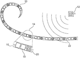
- FIG. 1 shows an exemplary embodiment of a cochlear implant system.
- the cochlear hearing aid system consists of an external part that comprises a microphone, a speech processor, an energy source, and a transmitter having a transmission antenna, as well as of an implanted part.
- the external part (the speech processor) is generally worn behind the ear, in previously known manner.
- the external part is merely shown in simplified form as a coil symbol 12 .
- the implanted part of the cochlear implant system consists of a helically shaped cochlear implant 10 , as well as an energy receiver, not shown here, having a reception antenna and a rectifier.
- the cochlear implant 10 comprises modules 14 that in turn each contain an electrode 16 , a decoder and control circuit 18 , as well as a signal receiver 20 having a reception antenna.
- the modules 14 are galvanically connected with the energy source, in this case the implanted rectifier, by way of a common two-wire line, and jointly encapsulated.
- the electrodes 16 of the modules 14 are disposed adjacent to the fibers of the auditory nerve, and power is applied to them in pulse-like manner, for stimulation of the fibers.
- Each module 14 represents a partial frequency range of the auditory spectrum being used. The higher the number and spatial density of the modules 14 can be made, the better the resolution of the auditory spectrum being used in partial frequency ranges, or the expansion of the auditory spectrum being used, and this leads to an improvement in auditory quality.
- the perception of loudness is determined by the amplitude and the total number of current pulses that stimulate the receptors within a certain period of time. Depending on the complexity of the original acoustic signal, one electrode 16 or multiple electrodes can jointly stimulate the auditory nerve fibers.
- Quasi parallel is understood to mean a time shift of the control commands that is brought about by serial data transmission and evaluation, and thereby the starts of power application to the electrodes, in terms of time, but this is unimportant physiologically. Even in the physiological condition of an ear having normal hearing, a ti-me offset of excitation along the cochlea comes about (“migration wave”).
- FIG. 2 shows details of a cochlear implant 10 having a data bus.
- a continuous data bus 24 which also can be used to supply energy to the individual modules 14 , leads to all the inputs of the decoder and control circuits 18 .
- the stimulation signal is evaluated and converted to current pulses that stimulate the receptors by way of the electrodes 16 .
- the stimulation signal contains information about the pulse frequency, and, optionally, about the pulse/pause ratio, the number of pulses, the pulse amplitude, and the pulse shape. If the wires of the data bus 24 are also being used to supply energy, the coded signals having the module addresses and stimulation signals are separated by way of a switch 26 .
- FIG. 3 shows details of a, cochlear implant 10 having signal and energy transmission at the same frequency for each module 14 separately.
- a receiver 28 having a reception antenna 30 is disposed ahead of the decoder and control circuit 18 .
- a signal output of the receiver 28 is connected with an input of the decoder and control circuit 18 .
- An energy output of the receiver 28 is connected with a rectifier, the output of which in turn is connected with an energy supply input of the decoder and control circuit 18 .
- FIG. 4 shows details of a cochlear implant 10 having signal and energy transmission at different frequencies.
- a receiver 32 having a reception antenna 34 is disposed ahead of the decoder and control circuit 18 .
- the receiver 32 having the reception antenna 34 is dimensioned for signal transmission at a high carrier frequency.
- a signal output of the receiver 32 is connected with an input of the decoder and control circuit 18 .
- An energy receiver 36 having a reception antenna 38 for low frequencies, common to all the modules 14 , is present for supplying energy.
- An energy output of the receiver 36 is connected with a rectifier, the output of which in turn is connected with a two-wire line 40 , which forms a loop to all the modules 14 .
Abstract
Description
Claims (7)
Applications Claiming Priority (4)
| Application Number | Priority Date | Filing Date | Title |
|---|---|---|---|
| DE102015114514.6A DE102015114514B4 (en) | 2015-08-31 | 2015-08-31 | Cochlear implant |
| DE102015114514 | 2015-08-31 | ||
| DE102015114514.6 | 2015-08-31 | ||
| PCT/DE2016/100342 WO2017036441A2 (en) | 2015-08-31 | 2016-07-27 | Cochlear implant |
Publications (2)
| Publication Number | Publication Date |
|---|---|
| US20180200504A1 US20180200504A1 (en) | 2018-07-19 |
| US10668272B2 true US10668272B2 (en) | 2020-06-02 |
Family
ID=56740727
Family Applications (1)
| Application Number | Title | Priority Date | Filing Date |
|---|---|---|---|
| US15/744,186 Active 2037-01-23 US10668272B2 (en) | 2015-08-31 | 2016-07-27 | Cochlear implant |
Country Status (4)
| Country | Link |
|---|---|
| US (1) | US10668272B2 (en) |
| EP (1) | EP3344329B1 (en) |
| DE (1) | DE102015114514B4 (en) |
| WO (1) | WO2017036441A2 (en) |
Citations (7)
| Publication number | Priority date | Publication date | Assignee | Title |
|---|---|---|---|---|
| US5061282A (en) | 1989-10-10 | 1991-10-29 | Jacobs Jared J | Cochlear implant auditory prosthesis |
| DE10018361A1 (en) | 2000-04-13 | 2001-10-25 | Implex Hear Tech Ag | At least partially implantable system for the rehabilitation of a hearing impairment |
| US20020051551A1 (en) * | 2000-08-25 | 2002-05-02 | Hans Leysieffer | Implantable medical device comprising an hermetically sealed housing |
| US20050015133A1 (en) * | 2001-06-29 | 2005-01-20 | Ibrahim Ibrahim Hanna | Multi-electrode cochlear implant system with distributed electronics |
| US20050029070A1 (en) | 2003-08-07 | 2005-02-10 | Jon Barnes | Viscous fan clutch actuated by a heating element and ambient air |
| US20130148828A1 (en) * | 2011-12-09 | 2013-06-13 | Andrew Fort | Controlling a Link for Different Load Conditions |
| US20160175590A1 (en) * | 2013-08-16 | 2016-06-23 | Advanced Bionics Ag | Connectorized cochlear implant systems |
-
2015
- 2015-08-31 DE DE102015114514.6A patent/DE102015114514B4/en not_active Expired - Fee Related
-
2016
- 2016-07-27 EP EP16754175.4A patent/EP3344329B1/en active Active
- 2016-07-27 WO PCT/DE2016/100342 patent/WO2017036441A2/en active Application Filing
- 2016-07-27 US US15/744,186 patent/US10668272B2/en active Active
Patent Citations (9)
| Publication number | Priority date | Publication date | Assignee | Title |
|---|---|---|---|---|
| US5061282A (en) | 1989-10-10 | 1991-10-29 | Jacobs Jared J | Cochlear implant auditory prosthesis |
| DE10018361A1 (en) | 2000-04-13 | 2001-10-25 | Implex Hear Tech Ag | At least partially implantable system for the rehabilitation of a hearing impairment |
| US20020029070A1 (en) | 2000-04-13 | 2002-03-07 | Hans Leysieffer | At least partially implantable system for rehabilitation a hearing disorder |
| US6575894B2 (en) | 2000-04-13 | 2003-06-10 | Cochlear Limited | At least partially implantable system for rehabilitation of a hearing disorder |
| US20020051551A1 (en) * | 2000-08-25 | 2002-05-02 | Hans Leysieffer | Implantable medical device comprising an hermetically sealed housing |
| US20050015133A1 (en) * | 2001-06-29 | 2005-01-20 | Ibrahim Ibrahim Hanna | Multi-electrode cochlear implant system with distributed electronics |
| US20050029070A1 (en) | 2003-08-07 | 2005-02-10 | Jon Barnes | Viscous fan clutch actuated by a heating element and ambient air |
| US20130148828A1 (en) * | 2011-12-09 | 2013-06-13 | Andrew Fort | Controlling a Link for Different Load Conditions |
| US20160175590A1 (en) * | 2013-08-16 | 2016-06-23 | Advanced Bionics Ag | Connectorized cochlear implant systems |
Non-Patent Citations (2)
| Title |
|---|
| English translation of the International Preliminary Report on Patentability and Written Opinion of the International Searching Authority of PCT/DE2016/100342, dated Mar. 15, 2018. |
| International Search Report of PCT/DE2016/100342, dated May 16, 2017. |
Also Published As
| Publication number | Publication date |
|---|---|
| WO2017036441A3 (en) | 2017-06-29 |
| EP3344329B1 (en) | 2019-09-04 |
| DE102015114514B4 (en) | 2017-03-30 |
| EP3344329A2 (en) | 2018-07-11 |
| WO2017036441A2 (en) | 2017-03-09 |
| DE102015114514A1 (en) | 2017-03-02 |
| US20180200504A1 (en) | 2018-07-19 |
Similar Documents
| Publication | Publication Date | Title |
|---|---|---|
| US11938331B2 (en) | Interleaving power and data in a transcutaneous communication link | |
| US20230166117A1 (en) | Power and data transfer in hearing prostheses | |
| US11348720B2 (en) | Inductance coil with varied geometry | |
| US11935684B2 (en) | Inductance coil path | |
| CN104284288B (en) | Signal processor for a hearing device and method for operating a hearing device | |
| US20110040350A1 (en) | FSK telemetry for cochlear implant | |
| US20120232616A1 (en) | Wireless communications in medical devices | |
| CN105491496A (en) | Hearing system | |
| EP2349464B1 (en) | Double branch cochlear implant electrode for penetration into the nerve tissue within the modiolus | |
| EP2240240B1 (en) | Stimulation channel conditioning | |
| EP3470112B1 (en) | A cochlear implant | |
| US8687831B2 (en) | Optimized energy and data transfer in hearing implant systems | |
| US10668272B2 (en) | Cochlear implant | |
| US10397715B2 (en) | System and method for improving data integrity and power efficiency | |
| EP3204108B1 (en) | Channel selection systems that employ temporal modification | |
| US11285322B2 (en) | Channel selection systems and methods that utilize fine structure information | |
| WO2014093288A1 (en) | Hearing implant housing with bottom surface lead |
Legal Events
| Date | Code | Title | Description |
|---|---|---|---|
| FEPP | Fee payment procedure |
Free format text: ENTITY STATUS SET TO UNDISCOUNTED (ORIGINAL EVENT CODE: BIG.); ENTITY STATUS OF PATENT OWNER: SMALL ENTITY |
|
| AS | Assignment |
Owner name: GOTTFRIED WILHELM LEIBNIZ UNIVERSITAET HANNOVER (60%), GERMANY Free format text: ASSIGNMENT OF ASSIGNORS INTEREST;ASSIGNORS:BLUME, HOLGER;ERTMER, WOLFGANG;LENARZ, THOMAS;AND OTHERS;SIGNING DATES FROM 20180116 TO 20180216;REEL/FRAME:045049/0069 Owner name: MEDIZINISCHE HOCHSCHULE HANNOVER (40%), GERMANY Free format text: ASSIGNMENT OF ASSIGNORS INTEREST;ASSIGNORS:BLUME, HOLGER;ERTMER, WOLFGANG;LENARZ, THOMAS;AND OTHERS;SIGNING DATES FROM 20180116 TO 20180216;REEL/FRAME:045049/0069 Owner name: GOTTFRIED WILHELM LEIBNIZ UNIVERSITAET HANNOVER (6 Free format text: ASSIGNMENT OF ASSIGNORS INTEREST;ASSIGNORS:BLUME, HOLGER;ERTMER, WOLFGANG;LENARZ, THOMAS;AND OTHERS;SIGNING DATES FROM 20180116 TO 20180216;REEL/FRAME:045049/0069 |
|
| FEPP | Fee payment procedure |
Free format text: ENTITY STATUS SET TO SMALL (ORIGINAL EVENT CODE: SMAL); ENTITY STATUS OF PATENT OWNER: SMALL ENTITY |
|
| STPP | Information on status: patent application and granting procedure in general |
Free format text: DOCKETED NEW CASE - READY FOR EXAMINATION |
|
| STPP | Information on status: patent application and granting procedure in general |
Free format text: NON FINAL ACTION MAILED |
|
| STPP | Information on status: patent application and granting procedure in general |
Free format text: RESPONSE TO NON-FINAL OFFICE ACTION ENTERED AND FORWARDED TO EXAMINER |
|
| STPP | Information on status: patent application and granting procedure in general |
Free format text: PUBLICATIONS -- ISSUE FEE PAYMENT RECEIVED |
|
| STCF | Information on status: patent grant |
Free format text: PATENTED CASE |
|
| CC | Certificate of correction | ||
| FEPP | Fee payment procedure |
Free format text: MAINTENANCE FEE REMINDER MAILED (ORIGINAL EVENT CODE: REM.); ENTITY STATUS OF PATENT OWNER: SMALL ENTITY |