US1066674A - Apparatus and method for the production of ozone. - Google Patents
Apparatus and method for the production of ozone. Download PDFInfo
- Publication number
- US1066674A US1066674A US67231412A US1912672314A US1066674A US 1066674 A US1066674 A US 1066674A US 67231412 A US67231412 A US 67231412A US 1912672314 A US1912672314 A US 1912672314A US 1066674 A US1066674 A US 1066674A
- Authority
- US
- United States
- Prior art keywords
- electrodes
- ozone
- compartments
- air
- compartment
- Prior art date
- Legal status (The legal status is an assumption and is not a legal conclusion. Google has not performed a legal analysis and makes no representation as to the accuracy of the status listed.)
- Expired - Lifetime
Links
- CBENFWSGALASAD-UHFFFAOYSA-N Ozone Chemical compound [O-][O+]=O CBENFWSGALASAD-UHFFFAOYSA-N 0.000 title description 13
- 238000000034 method Methods 0.000 title description 13
- 238000004519 manufacturing process Methods 0.000 title description 4
- 239000002826 coolant Substances 0.000 description 7
- 238000001816 cooling Methods 0.000 description 7
- 239000004020 conductor Substances 0.000 description 6
- QGZKDVFQNNGYKY-UHFFFAOYSA-N Ammonia Chemical compound N QGZKDVFQNNGYKY-UHFFFAOYSA-N 0.000 description 2
- 239000012212 insulator Substances 0.000 description 2
- 229910021529 ammonia Inorganic materials 0.000 description 1
- 230000015572 biosynthetic process Effects 0.000 description 1
- 230000006378 damage Effects 0.000 description 1
Images


Classifications
-
- C—CHEMISTRY; METALLURGY
- C01—INORGANIC CHEMISTRY
- C01B—NON-METALLIC ELEMENTS; COMPOUNDS THEREOF; METALLOIDS OR COMPOUNDS THEREOF NOT COVERED BY SUBCLASS C01C
- C01B13/00—Oxygen; Ozone; Oxides or hydroxides in general
- C01B13/10—Preparation of ozone
- C01B13/11—Preparation of ozone by electric discharge
-
- Y—GENERAL TAGGING OF NEW TECHNOLOGICAL DEVELOPMENTS; GENERAL TAGGING OF CROSS-SECTIONAL TECHNOLOGIES SPANNING OVER SEVERAL SECTIONS OF THE IPC; TECHNICAL SUBJECTS COVERED BY FORMER USPC CROSS-REFERENCE ART COLLECTIONS [XRACs] AND DIGESTS
- Y10—TECHNICAL SUBJECTS COVERED BY FORMER USPC
- Y10S—TECHNICAL SUBJECTS COVERED BY FORMER USPC CROSS-REFERENCE ART COLLECTIONS [XRACs] AND DIGESTS
- Y10S55/00—Gas separation
- Y10S55/38—Tubular collector electrode
Definitions
- My invention relates to apparatus and methods for producing ozone of the general kind described in my Patents Nos. 906,081 and 906,4i68.
- the objects of my invention are to provide apparatus for producing ozone which will be more reliable in operation than apparatus heretofore used, which will be compact and durable and which when used in practising my improved method forming a part of this invention, will give an increased efiiciency and a higher concentration than has heretofore been obtained.
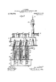
- Figure 1 of the drawing is a sectional view of the apparatus taken on line 11 of the apparatus as shown in Fig. 3.
- Fig. 2 is a similar sectional view taken on the line 22 of Fig. 3 facing the other side of the apparatus from Fig. 1.
- Fig. 3 is an end elevation of the apparatus shown in Figs. 1 and 2, the end walls of the upper and lower compartments being broken away.
- Fig. t is a sectional view taken on the line 38 of Fig. 1'.
- Fig. 5 is a sectional View taken on line L-i of Fig. 1.
- the numeral 1 designates a lower casing forming the base of the apparatus, which casing is divided into three compartments 2, 3 and a (see Fig. 5).
- the numeral 5 designates an upper casing which is divided into four compartments 6, 7, 8 and 9 (see Fig. a).
- Hollow electrodes 10,11, 12, 13, 14 and 15 arranged in two parallel rows open at 7, 8 and 9 and at their lower ends into the compartments 2, 3 and 4 and the compartments serve to connect these hollow electrodes in series with one another.
- the hollow electrodes each contain a dielectric tube 18 and each dielectric tube contains and sup ports an elongated inner electrode 19 having discharge rings 20 spaced thereon. The discharges take place between the rings 20 and the hollow electrodes through the dielectric.
- the inner electrodes 1.) are slidably mounted in the dielectric tubes so that in case they are damaged they can be readily removed through the windows 26. At their lower ends the dielectric tubes extend a considerable distance below the lower ends of the electrodes and this is a desirable feature since it prevents the formation of arcs between the lower ends of the inner electrodes and the grounded casing.
- the numeral 16 designates the air intake, which is arranged to deliver air suitably cooled and dried into the compartment 6, from which compartment it passes down the electrode 10 into the lower compartment 2, then up through the electrode 11 into the compartment 7, then down electrode 12 into compartment 3, then up electrode 13 into compartment 8, then down electrode 14 into compartment 1, and then up electrode 15 and out of the machine at the opening 17.
- the flow of air through the apparatus is indicated in Figs. 1 and 2 by feathered arrows.
- the hollow electrodes are surrounded by cooling jackets 27, 28, 29, 80, 31 and 32 and these are connected in series with one another by conduits 33.
- the numeral 34 designates the intake for the cooling medium, which, because of the series arrangement of the cooling jackets is caused to pass through the. jackets 2T, 28, 29, 30, 31 and 32 in the order named and out of the machine at the opening 85.
- the course of the cooling medium through the jackets and the conduits connecting them is indicated by unfeathered arrows. It will thus be seen that the cooling medium moves along the hollow electrodes in a direction always OJPOSltG that of the air passing through tie electrodes.
- a conductor 21 enters the machine through the insulator 22 and its lower end is connected to the horizontal conductors 23, which extend into the several compartments and are disposed ad acent the tops of the inner electrodes.
- the hor zontal conductors pass through and are lnsulated from the walls of the compartments by insulators 40.
- Connections as pivoted to the horizontal conductors 23 convey the current to the inner electrodes 19. These connections may be swung back as shown in Fig. 8, so as to permit the removal of electrodes l9.
- the air forced into the machine through opening 16 while passing successlvely, through the several electrodes is sub ected alternately to electrical discharges from the rings 20 and to the cooling action of the cooling medium in the jackets. Since the air and cooling medium flow in opposite d1- rections throughout their courses, the temperature of the air may be maintamed substantially constant and this is important because any rise in temperature of the a 1r while undergoing treatment would result 1n the destruction of some of the ozone previously generated.
- I preferably employ liquefied ammonia as a cooling medium and the apparatus shown is preferably inclosed in a heat insulating case in order that a low temperature may be maintained.
- the method herein described is an improvement on the method described in my Patent N 0. 906368 in that while embodying the idea of alternately ozonizing and cooling the air, it adds the additional feature of causing the air to pass through tubes arranged in series and the cooling medium to move in contact with the tubes but always in an opposite direction.
- the method of generating ozone which consists in progressively subjecting air to a series of electrical discharges while moving in one direction and in simultaneously cooling the air and resultant ozone by subjecting it to the action of a cooling fluld moving in the opposite direction, substantially as described.
- two sets of compartments a plurality of hollow electrodes, one end of each electrode connected to a compartment of each set, whereby all of the compartments of one set are connected through the hollow electrodes with all of the compartments of the other set for the purpose of passing air to be ozonized therethrough, substantially as described.
- a lower and an upper compartment hollow electrodes connecting the lower and upper compartments and arranged in series, inner electrodes in the hollow electrodes and separated therefrom by dielectric tubes which extend below both electrodes, substantially as described.
Landscapes
- Chemical & Material Sciences (AREA)
- Organic Chemistry (AREA)
- Inorganic Chemistry (AREA)
- Oxygen, Ozone, And Oxides In General (AREA)
Description
J. STEYNIS.
APPARATUS AND METHOD FOR THE PRODUCTION OF OZONE. APPLICATION FILED urm'o, 1912.
1,066,67% Patented July 8, 1913.
3 SHEETS-SHEET 1.
J. STBYNIS. APPARATUS AND METHOD FOR THE vnonucwron or OZONE. APPLIOATIOH FILED JAILZO, 1912.
1 066 674, Patented July 8, 1913.
3 SHEETS-SHEET 2.
V 1? I I II I' I I I I 51 8 i v" I 9 ;'15 3 EI:-I\ 15 I Z 14 E 3 15 I I j I \l g I I I 55 I I I m I I Q 0 I I -20 I I I I 2? 2.9 I I 26 I l r I m 65 I I I I I I I I I III [8 I I I ,8
i WWW/aces: Z gvwe'wtoz UNFFED PATENT @FFKQE.
JAN STEYNIS, OF NEW YORK, N. Y., ASSIGNOR 'IO STEYNIS OZONE COMPANY, A CORIPORATION OF NEW YORK.
APPARATUS AND METHOD FOR THE PRODUCTION OF OZONE.
Specification of Letters Patent.
Patented July 8, 1913.
Application filed January 20, 1912. Serial No. 672,314:
To all whom it may concern:
Be it known that 1, JAN STEYNIS, a subject of the Queen of the Netherlands, residing in the city, county, and State of New York, have invented certain new and useful Improvements in Apparatus and Methods for the Production of Ozone, of which the following is a full, clear, and complete disclosure.
My invention relates to apparatus and methods for producing ozone of the general kind described in my Patents Nos. 906,081 and 906,4i68.
The objects of my invention are to provide apparatus for producing ozone which will be more reliable in operation than apparatus heretofore used, which will be compact and durable and which when used in practising my improved method forming a part of this invention, will give an increased efiiciency and a higher concentration than has heretofore been obtained.
Other objects and advantages will be pointed out in connection with the description of the invention.
In the drawing accompanying and forming a part of this specification, I have illus trated one embodiment of my improved apparatus.
Figure 1 of the drawing is a sectional view of the apparatus taken on line 11 of the apparatus as shown in Fig. 3. Fig. 2 is a similar sectional view taken on the line 22 of Fig. 3 facing the other side of the apparatus from Fig. 1. Fig. 3 is an end elevation of the apparatus shown in Figs. 1 and 2, the end walls of the upper and lower compartments being broken away. Fig. t is a sectional view taken on the line 38 of Fig. 1'. Fig. 5 is a sectional View taken on line L-i of Fig. 1.
Referring in detail to the mechanism shown in these figures, the numeral 1 designates a lower casing forming the base of the apparatus, which casing is divided into three compartments 2, 3 and a (see Fig. 5).
The numeral 5 designates an upper casing which is divided into four compartments 6, 7, 8 and 9 (see Fig. a).
The numeral 16 designates the air intake, which is arranged to deliver air suitably cooled and dried into the compartment 6, from which compartment it passes down the electrode 10 into the lower compartment 2, then up through the electrode 11 into the compartment 7, then down electrode 12 into compartment 3, then up electrode 13 into compartment 8, then down electrode 14 into compartment 1, and then up electrode 15 and out of the machine at the opening 17. The flow of air through the apparatus is indicated in Figs. 1 and 2 by feathered arrows. The hollow electrodes are surrounded by cooling jackets 27, 28, 29, 80, 31 and 32 and these are connected in series with one another by conduits 33.
The numeral 34 designates the intake for the cooling medium, which, because of the series arrangement of the cooling jackets is caused to pass through the. jackets 2T, 28, 29, 30, 31 and 32 in the order named and out of the machine at the opening 85. The course of the cooling medium through the jackets and the conduits connecting them is indicated by unfeathered arrows. It will thus be seen that the cooling medium moves along the hollow electrodes in a direction always OJPOSltG that of the air passing through tie electrodes.
Currentfor producing the discharges is supplied to the inner eleetrodes in the following manner. A conductor 21 enters the machine through the insulator 22 and its lower end is connected to the horizontal conductors 23, which extend into the several compartments and are disposed ad acent the tops of the inner electrodes. The hor zontal conductors pass through and are lnsulated from the walls of the compartments by insulators 40. Connections as pivoted to the horizontal conductors 23 convey the current to the inner electrodes 19. These connections may be swung back as shown in Fig. 8, so as to permit the removal of electrodes l9.
The air forced into the machine through opening 16 while passing successlvely, through the several electrodes is sub ected alternately to electrical discharges from the rings 20 and to the cooling action of the cooling medium in the jackets. Since the air and cooling medium flow in opposite d1- rections throughout their courses, the temperature of the air may be maintamed substantially constant and this is important because any rise in temperature of the a 1r while undergoing treatment would result 1n the destruction of some of the ozone previously generated. By arranging the hollow electrodes in series, I insure a uniform flow through all the electrodes which is not possible where the tubes are arranged i parallel.
With a machine of the kind above described I have obtained a concentration of 7.26 grams of ozone per cubic meter of air treated, with an eificiency of 227 grams of ozone per kilowatt hour of current used. I have also obtained a concentration of 9.52 grams of ozone per cubic meter of air treated, with an efliciency of 171 grams of ozone per kilowatt of current consumed. These tests were made at an average temperature of 28 Fahrenheit. The difference in these results is due to the ditference of flow of the air while passing through the machine. In the latter case the air was made to flow more slowly than in the first. The values of concentration and efiiciency in the above cases, I believe, are considerably higher than have heretofore been obtainable with the old methods and apparatus.
In practising my improved method and in operating the apparatus above described I preferably employ liquefied ammonia as a cooling medium and the apparatus shown is preferably inclosed in a heat insulating case in order that a low temperature may be maintained.
"The apparatus herein described has some features in common with but is an improvement on the apparatus described in my pendlng appllcation Serial No. 603,276,\
from which it is difierentiated by the series arrangement of the cooling and ozonizing tubes and by the replacing of the contact plates in the lower compartment of the ap paratus of the earlier application by the conductors and pivoted contacts all in the upper compartments. By employing conductors located in the upper casing 5, I am able to extend the dielectric tubes a substantial distance below the lower end of the electrodes, which is desirable for the reasons above pointed out.
The method herein described is an improvement on the method described in my Patent N 0. 906368 in that while embodying the idea of alternately ozonizing and cooling the air, it adds the additional feature of causing the air to pass through tubes arranged in series and the cooling medium to move in contact with the tubes but always in an opposite direction.
While I have described one embodiment of my apparatus and the preferred way of practising my method, still I am aware that these may be varied by those skilled in the art without departing from the scope of my claims.
What I claim is:
1. The method of generating ozone which consists in progressively subjecting air to a series of electrical discharges while moving in one direction and in simultaneously cooling the air and resultant ozone by subjecting it to the action of a cooling fluld moving in the opposite direction, substantially as described.
2. In an apparatus of the kind described, two sets of compartments, a plurality of hollow electrodes, one end of each electrode connected to a compartment of each set, whereby all of the compartments of one set are connected through the hollow electrodes with all of the compartments of the other set for the purpose of passing air to be ozonized therethrough, substantially as described.
3. In an apparatus of the kind described, oppositely disposed casings each divided into separate compartments, a plurality of hollow electrodes connecting the compartments of one casing with the compartments of the other casing and arranged in series with each other for the purpose of passing air to be ozonized therethrough, substantially as described.
4. In an apparatus of the kind described, a lower and an upper compartment, hollow electrodes connecting the lower and upper compartments and arranged in series, inner electrodes in the hollow electrodes and separated therefrom by dielectric tubes which extend below both electrodes, substantially as described.
5. 'In an apparatus of the kind described,
two sets of compartments, hollow electrodes the electrodes and pivoted connections exconnecting the compartments of one set with tending from the bars to the ends of the those of the other, and arranged in series, inner electrodes, substantially as described. 10
inner electrodes in the hollow electrodes and JAN STEYNIS. separated therefrom by dielectric tubes Witnesses: Y which extend below both electrodes, dis- WALTER S. JONES,
tributing bars disposed adjacent the ends of R. M. RICKETTS.
Priority Applications (1)
| Application Number | Priority Date | Filing Date | Title |
|---|---|---|---|
| US67231412A US1066674A (en) | 1912-01-20 | 1912-01-20 | Apparatus and method for the production of ozone. |
Applications Claiming Priority (1)
| Application Number | Priority Date | Filing Date | Title |
|---|---|---|---|
| US67231412A US1066674A (en) | 1912-01-20 | 1912-01-20 | Apparatus and method for the production of ozone. |
Publications (1)
| Publication Number | Publication Date |
|---|---|
| US1066674A true US1066674A (en) | 1913-07-08 |
Family
ID=3134917
Family Applications (1)
| Application Number | Title | Priority Date | Filing Date |
|---|---|---|---|
| US67231412A Expired - Lifetime US1066674A (en) | 1912-01-20 | 1912-01-20 | Apparatus and method for the production of ozone. |
Country Status (1)
| Country | Link |
|---|---|
| US (1) | US1066674A (en) |
Cited By (2)
| Publication number | Priority date | Publication date | Assignee | Title |
|---|---|---|---|---|
| US2876188A (en) * | 1955-03-21 | 1959-03-03 | Air Reduction | Ozone manufacture |
| US3919064A (en) * | 1969-06-04 | 1975-11-11 | Purification Sciences Inc | Corona reactor method and apparatus |
-
1912
- 1912-01-20 US US67231412A patent/US1066674A/en not_active Expired - Lifetime
Cited By (2)
| Publication number | Priority date | Publication date | Assignee | Title |
|---|---|---|---|---|
| US2876188A (en) * | 1955-03-21 | 1959-03-03 | Air Reduction | Ozone manufacture |
| US3919064A (en) * | 1969-06-04 | 1975-11-11 | Purification Sciences Inc | Corona reactor method and apparatus |
Similar Documents
| Publication | Publication Date | Title |
|---|---|---|
| US4079260A (en) | Ozone generator | |
| US788557A (en) | Electrical ozonizer. | |
| US1066674A (en) | Apparatus and method for the production of ozone. | |
| US1344330A (en) | Orifice-precipitator | |
| US1333838A (en) | Art of producing charges for power devices | |
| US1744173A (en) | Process of treating organic substances in liquid state electrochemically | |
| US640694A (en) | Apparatus for producing electric discharges. | |
| US1162415A (en) | Process of and apparatus for producing ozone. | |
| US1201379A (en) | Apparatus for the production of ozone. | |
| US1312484A (en) | Apparatus for ozone generation | |
| US831434A (en) | Water-purifier. | |
| US977336A (en) | Means for filtering air and producing ozone. | |
| US577636A (en) | Emile andreoli | |
| US2022650A (en) | Hydrogen peroxide process | |
| US976002A (en) | Production of long stable electric arcs. | |
| US1201380A (en) | Apparatus for producing ozone. | |
| US1437189A (en) | Electrolytic condenser | |
| US1368560A (en) | Ozone-generator | |
| US1035489A (en) | Apparatus for the production of ozone. | |
| US772862A (en) | Process of electrically treating gases. | |
| US1095425A (en) | Process and apparatus for the production of long continuous electric arcs. | |
| US671507A (en) | Apparatus for electrically treating gases. | |
| US850985A (en) | Air cooler and purifier. | |
| US632391A (en) | Ozone-generator. | |
| US580244A (en) | yarnold |