US10663776B1 - Enhanced privacy switchable backlight system - Google Patents
Enhanced privacy switchable backlight system Download PDFInfo
- Publication number
- US10663776B1 US10663776B1 US16/263,295 US201916263295A US10663776B1 US 10663776 B1 US10663776 B1 US 10663776B1 US 201916263295 A US201916263295 A US 201916263295A US 10663776 B1 US10663776 B1 US 10663776B1
- Authority
- US
- United States
- Prior art keywords
- barrier
- display component
- lens array
- viewing side
- slit structure
- Prior art date
- Legal status (The legal status is an assumption and is not a legal conclusion. Google has not performed a legal analysis and makes no representation as to the accuracy of the status listed.)
- Active
Links
- 230000004888 barrier function Effects 0.000 claims abstract description 206
- 239000000758 substrate Substances 0.000 claims description 25
- 239000011358 absorbing material Substances 0.000 claims description 12
- 239000004973 liquid crystal related substance Substances 0.000 claims description 12
- 229910052751 metal Inorganic materials 0.000 claims description 10
- 239000002184 metal Substances 0.000 claims description 10
- 230000000694 effects Effects 0.000 claims description 9
- 238000000926 separation method Methods 0.000 claims description 7
- 125000006850 spacer group Chemical group 0.000 claims description 7
- 210000002858 crystal cell Anatomy 0.000 claims description 6
- 238000009826 distribution Methods 0.000 claims description 5
- 210000004027 cell Anatomy 0.000 description 33
- 239000011295 pitch Substances 0.000 description 22
- 230000003287 optical effect Effects 0.000 description 18
- 239000000463 material Substances 0.000 description 10
- 238000003491 array Methods 0.000 description 8
- BQCADISMDOOEFD-UHFFFAOYSA-N Silver Chemical compound [Ag] BQCADISMDOOEFD-UHFFFAOYSA-N 0.000 description 7
- 239000004332 silver Substances 0.000 description 7
- 229910052709 silver Inorganic materials 0.000 description 7
- 239000003292 glue Substances 0.000 description 6
- 239000011521 glass Substances 0.000 description 5
- 238000004064 recycling Methods 0.000 description 5
- 230000005540 biological transmission Effects 0.000 description 4
- 239000011248 coating agent Substances 0.000 description 4
- 238000000576 coating method Methods 0.000 description 4
- VYZAMTAEIAYCRO-UHFFFAOYSA-N Chromium Chemical compound [Cr] VYZAMTAEIAYCRO-UHFFFAOYSA-N 0.000 description 3
- 239000004411 aluminium Substances 0.000 description 3
- 229910052782 aluminium Inorganic materials 0.000 description 3
- XAGFODPZIPBFFR-UHFFFAOYSA-N aluminium Chemical compound [Al] XAGFODPZIPBFFR-UHFFFAOYSA-N 0.000 description 3
- 238000000149 argon plasma sintering Methods 0.000 description 3
- 230000001276 controlling effect Effects 0.000 description 3
- 239000000839 emulsion Substances 0.000 description 3
- 238000000034 method Methods 0.000 description 3
- 230000003595 spectral effect Effects 0.000 description 3
- 239000012780 transparent material Substances 0.000 description 3
- 239000004983 Polymer Dispersed Liquid Crystal Substances 0.000 description 2
- 230000009286 beneficial effect Effects 0.000 description 2
- 238000000151 deposition Methods 0.000 description 2
- 230000004075 alteration Effects 0.000 description 1
- 238000000429 assembly Methods 0.000 description 1
- 230000000712 assembly Effects 0.000 description 1
- 230000002238 attenuated effect Effects 0.000 description 1
- 230000000903 blocking effect Effects 0.000 description 1
- 230000000052 comparative effect Effects 0.000 description 1
- 230000001419 dependent effect Effects 0.000 description 1
- 239000002019 doping agent Substances 0.000 description 1
- 230000009977 dual effect Effects 0.000 description 1
- 230000002708 enhancing effect Effects 0.000 description 1
- 238000005530 etching Methods 0.000 description 1
- AMGQUBHHOARCQH-UHFFFAOYSA-N indium;oxotin Chemical compound [In].[Sn]=O AMGQUBHHOARCQH-UHFFFAOYSA-N 0.000 description 1
- 238000004519 manufacturing process Methods 0.000 description 1
- 238000005259 measurement Methods 0.000 description 1
- 239000007769 metal material Substances 0.000 description 1
- 239000000203 mixture Substances 0.000 description 1
- 238000012986 modification Methods 0.000 description 1
- 230000004048 modification Effects 0.000 description 1
- 238000000206 photolithography Methods 0.000 description 1
- 230000009467 reduction Effects 0.000 description 1
- 238000002310 reflectometry Methods 0.000 description 1
- 230000001105 regulatory effect Effects 0.000 description 1
- 239000011347 resin Substances 0.000 description 1
- 229920005989 resin Polymers 0.000 description 1
- 238000012216 screening Methods 0.000 description 1
Images


Classifications
-
- G—PHYSICS
- G02—OPTICS
- G02F—OPTICAL DEVICES OR ARRANGEMENTS FOR THE CONTROL OF LIGHT BY MODIFICATION OF THE OPTICAL PROPERTIES OF THE MEDIA OF THE ELEMENTS INVOLVED THEREIN; NON-LINEAR OPTICS; FREQUENCY-CHANGING OF LIGHT; OPTICAL LOGIC ELEMENTS; OPTICAL ANALOGUE/DIGITAL CONVERTERS
- G02F1/00—Devices or arrangements for the control of the intensity, colour, phase, polarisation or direction of light arriving from an independent light source, e.g. switching, gating or modulating; Non-linear optics
- G02F1/01—Devices or arrangements for the control of the intensity, colour, phase, polarisation or direction of light arriving from an independent light source, e.g. switching, gating or modulating; Non-linear optics for the control of the intensity, phase, polarisation or colour
- G02F1/13—Devices or arrangements for the control of the intensity, colour, phase, polarisation or direction of light arriving from an independent light source, e.g. switching, gating or modulating; Non-linear optics for the control of the intensity, phase, polarisation or colour based on liquid crystals, e.g. single liquid crystal display cells
- G02F1/1323—Arrangements for providing a switchable viewing angle
-
- G—PHYSICS
- G02—OPTICS
- G02B—OPTICAL ELEMENTS, SYSTEMS OR APPARATUS
- G02B6/00—Light guides; Structural details of arrangements comprising light guides and other optical elements, e.g. couplings
- G02B6/0001—Light guides; Structural details of arrangements comprising light guides and other optical elements, e.g. couplings specially adapted for lighting devices or systems
- G02B6/0011—Light guides; Structural details of arrangements comprising light guides and other optical elements, e.g. couplings specially adapted for lighting devices or systems the light guides being planar or of plate-like form
- G02B6/0013—Means for improving the coupling-in of light from the light source into the light guide
- G02B6/0023—Means for improving the coupling-in of light from the light source into the light guide provided by one optical element, or plurality thereof, placed between the light guide and the light source, or around the light source
- G02B6/0031—Reflecting element, sheet or layer
-
- G—PHYSICS
- G02—OPTICS
- G02B—OPTICAL ELEMENTS, SYSTEMS OR APPARATUS
- G02B6/00—Light guides; Structural details of arrangements comprising light guides and other optical elements, e.g. couplings
- G02B6/0001—Light guides; Structural details of arrangements comprising light guides and other optical elements, e.g. couplings specially adapted for lighting devices or systems
- G02B6/0011—Light guides; Structural details of arrangements comprising light guides and other optical elements, e.g. couplings specially adapted for lighting devices or systems the light guides being planar or of plate-like form
- G02B6/0033—Means for improving the coupling-out of light from the light guide
- G02B6/0035—Means for improving the coupling-out of light from the light guide provided on the surface of the light guide or in the bulk of it
- G02B6/004—Scattering dots or dot-like elements, e.g. microbeads, scattering particles, nanoparticles
- G02B6/0041—Scattering dots or dot-like elements, e.g. microbeads, scattering particles, nanoparticles provided in the bulk of the light guide
-
- G—PHYSICS
- G02—OPTICS
- G02B—OPTICAL ELEMENTS, SYSTEMS OR APPARATUS
- G02B6/00—Light guides; Structural details of arrangements comprising light guides and other optical elements, e.g. couplings
- G02B6/0001—Light guides; Structural details of arrangements comprising light guides and other optical elements, e.g. couplings specially adapted for lighting devices or systems
- G02B6/0011—Light guides; Structural details of arrangements comprising light guides and other optical elements, e.g. couplings specially adapted for lighting devices or systems the light guides being planar or of plate-like form
- G02B6/0075—Arrangements of multiple light guides
- G02B6/0076—Stacked arrangements of multiple light guides of the same or different cross-sectional area
-
- G—PHYSICS
- G02—OPTICS
- G02F—OPTICAL DEVICES OR ARRANGEMENTS FOR THE CONTROL OF LIGHT BY MODIFICATION OF THE OPTICAL PROPERTIES OF THE MEDIA OF THE ELEMENTS INVOLVED THEREIN; NON-LINEAR OPTICS; FREQUENCY-CHANGING OF LIGHT; OPTICAL LOGIC ELEMENTS; OPTICAL ANALOGUE/DIGITAL CONVERTERS
- G02F1/00—Devices or arrangements for the control of the intensity, colour, phase, polarisation or direction of light arriving from an independent light source, e.g. switching, gating or modulating; Non-linear optics
- G02F1/01—Devices or arrangements for the control of the intensity, colour, phase, polarisation or direction of light arriving from an independent light source, e.g. switching, gating or modulating; Non-linear optics for the control of the intensity, phase, polarisation or colour
- G02F1/13—Devices or arrangements for the control of the intensity, colour, phase, polarisation or direction of light arriving from an independent light source, e.g. switching, gating or modulating; Non-linear optics for the control of the intensity, phase, polarisation or colour based on liquid crystals, e.g. single liquid crystal display cells
- G02F1/133—Constructional arrangements; Operation of liquid crystal cells; Circuit arrangements
- G02F1/1333—Constructional arrangements; Manufacturing methods
- G02F1/1335—Structural association of cells with optical devices, e.g. polarisers or reflectors
- G02F1/1336—Illuminating devices
- G02F1/133602—Direct backlight
-
- G—PHYSICS
- G09—EDUCATION; CRYPTOGRAPHY; DISPLAY; ADVERTISING; SEALS
- G09G—ARRANGEMENTS OR CIRCUITS FOR CONTROL OF INDICATING DEVICES USING STATIC MEANS TO PRESENT VARIABLE INFORMATION
- G09G3/00—Control arrangements or circuits, of interest only in connection with visual indicators other than cathode-ray tubes
- G09G3/20—Control arrangements or circuits, of interest only in connection with visual indicators other than cathode-ray tubes for presentation of an assembly of a number of characters, e.g. a page, by composing the assembly by combination of individual elements arranged in a matrix no fixed position being assigned to or needed to be assigned to the individual characters or partial characters
- G09G3/34—Control arrangements or circuits, of interest only in connection with visual indicators other than cathode-ray tubes for presentation of an assembly of a number of characters, e.g. a page, by composing the assembly by combination of individual elements arranged in a matrix no fixed position being assigned to or needed to be assigned to the individual characters or partial characters by control of light from an independent source
- G09G3/3406—Control of illumination source
- G09G3/342—Control of illumination source using several illumination sources separately controlled corresponding to different display panel areas, e.g. along one dimension such as lines
- G09G3/3426—Control of illumination source using several illumination sources separately controlled corresponding to different display panel areas, e.g. along one dimension such as lines the different display panel areas being distributed in two dimensions, e.g. matrix
-
- G—PHYSICS
- G02—OPTICS
- G02F—OPTICAL DEVICES OR ARRANGEMENTS FOR THE CONTROL OF LIGHT BY MODIFICATION OF THE OPTICAL PROPERTIES OF THE MEDIA OF THE ELEMENTS INVOLVED THEREIN; NON-LINEAR OPTICS; FREQUENCY-CHANGING OF LIGHT; OPTICAL LOGIC ELEMENTS; OPTICAL ANALOGUE/DIGITAL CONVERTERS
- G02F1/00—Devices or arrangements for the control of the intensity, colour, phase, polarisation or direction of light arriving from an independent light source, e.g. switching, gating or modulating; Non-linear optics
- G02F1/01—Devices or arrangements for the control of the intensity, colour, phase, polarisation or direction of light arriving from an independent light source, e.g. switching, gating or modulating; Non-linear optics for the control of the intensity, phase, polarisation or colour
- G02F1/13—Devices or arrangements for the control of the intensity, colour, phase, polarisation or direction of light arriving from an independent light source, e.g. switching, gating or modulating; Non-linear optics for the control of the intensity, phase, polarisation or colour based on liquid crystals, e.g. single liquid crystal display cells
- G02F1/133—Constructional arrangements; Operation of liquid crystal cells; Circuit arrangements
- G02F1/1333—Constructional arrangements; Manufacturing methods
- G02F1/1335—Structural association of cells with optical devices, e.g. polarisers or reflectors
- G02F1/1336—Illuminating devices
- G02F1/133602—Direct backlight
- G02F1/133606—Direct backlight including a specially adapted diffusing, scattering or light controlling members
- G02F1/133607—Direct backlight including a specially adapted diffusing, scattering or light controlling members the light controlling member including light directing or refracting elements, e.g. prisms or lenses
-
- G—PHYSICS
- G02—OPTICS
- G02F—OPTICAL DEVICES OR ARRANGEMENTS FOR THE CONTROL OF LIGHT BY MODIFICATION OF THE OPTICAL PROPERTIES OF THE MEDIA OF THE ELEMENTS INVOLVED THEREIN; NON-LINEAR OPTICS; FREQUENCY-CHANGING OF LIGHT; OPTICAL LOGIC ELEMENTS; OPTICAL ANALOGUE/DIGITAL CONVERTERS
- G02F1/00—Devices or arrangements for the control of the intensity, colour, phase, polarisation or direction of light arriving from an independent light source, e.g. switching, gating or modulating; Non-linear optics
- G02F1/01—Devices or arrangements for the control of the intensity, colour, phase, polarisation or direction of light arriving from an independent light source, e.g. switching, gating or modulating; Non-linear optics for the control of the intensity, phase, polarisation or colour
- G02F1/13—Devices or arrangements for the control of the intensity, colour, phase, polarisation or direction of light arriving from an independent light source, e.g. switching, gating or modulating; Non-linear optics for the control of the intensity, phase, polarisation or colour based on liquid crystals, e.g. single liquid crystal display cells
- G02F1/133—Constructional arrangements; Operation of liquid crystal cells; Circuit arrangements
- G02F1/1333—Constructional arrangements; Manufacturing methods
- G02F1/1335—Structural association of cells with optical devices, e.g. polarisers or reflectors
- G02F1/1336—Illuminating devices
- G02F1/133626—Illuminating devices providing two modes of illumination, e.g. day-night
-
- G02F2001/133626—
-
- G—PHYSICS
- G02—OPTICS
- G02F—OPTICAL DEVICES OR ARRANGEMENTS FOR THE CONTROL OF LIGHT BY MODIFICATION OF THE OPTICAL PROPERTIES OF THE MEDIA OF THE ELEMENTS INVOLVED THEREIN; NON-LINEAR OPTICS; FREQUENCY-CHANGING OF LIGHT; OPTICAL LOGIC ELEMENTS; OPTICAL ANALOGUE/DIGITAL CONVERTERS
- G02F2203/00—Function characteristic
- G02F2203/62—Switchable arrangements whereby the element being usually not switchable
-
- G—PHYSICS
- G09—EDUCATION; CRYPTOGRAPHY; DISPLAY; ADVERTISING; SEALS
- G09G—ARRANGEMENTS OR CIRCUITS FOR CONTROL OF INDICATING DEVICES USING STATIC MEANS TO PRESENT VARIABLE INFORMATION
- G09G2320/00—Control of display operating conditions
- G09G2320/02—Improving the quality of display appearance
- G09G2320/028—Improving the quality of display appearance by changing the viewing angle properties, e.g. widening the viewing angle, adapting the viewing angle to the view direction
-
- G—PHYSICS
- G09—EDUCATION; CRYPTOGRAPHY; DISPLAY; ADVERTISING; SEALS
- G09G—ARRANGEMENTS OR CIRCUITS FOR CONTROL OF INDICATING DEVICES USING STATIC MEANS TO PRESENT VARIABLE INFORMATION
- G09G2320/00—Control of display operating conditions
- G09G2320/06—Adjustment of display parameters
- G09G2320/068—Adjustment of display parameters for control of viewing angle adjustment
-
- G—PHYSICS
- G09—EDUCATION; CRYPTOGRAPHY; DISPLAY; ADVERTISING; SEALS
- G09G—ARRANGEMENTS OR CIRCUITS FOR CONTROL OF INDICATING DEVICES USING STATIC MEANS TO PRESENT VARIABLE INFORMATION
- G09G2354/00—Aspects of interface with display user
-
- G—PHYSICS
- G09—EDUCATION; CRYPTOGRAPHY; DISPLAY; ADVERTISING; SEALS
- G09G—ARRANGEMENTS OR CIRCUITS FOR CONTROL OF INDICATING DEVICES USING STATIC MEANS TO PRESENT VARIABLE INFORMATION
- G09G2380/00—Specific applications
- G09G2380/10—Automotive applications
Definitions
- the present invention relates to a switchable privacy display system for use, for example, as an automotive display involving a backlight system that is switchable between a strong privacy mode and a bright public mode.
- Displays in automotive vehicles are becoming more and more prominent.
- the main obstacle preventing this from becoming a reality is privacy: by law in many jurisdictions and otherwise for general safety concerns, a driver must not be able to view moving image content on a display while driving. Accordingly, if a passenger is watching video content on the dashboard display, no light (or no variation of light level) is to be visible from the driver's position.
- Such result necessitates a strong privacy display, by which image content is visible only from within a specific and limited viewing angle range, and otherwise generally is not visible to a viewer outside of such viewing angle range.
- FIG. 1A is a schematic drawing depicting a liquid crystal device (LCD) configuration 10 as is conventional in the art.
- FIG. 1B is a schematic drawing depicting an LCD configuration 20 that is representative of an improved privacy display designed by Applicant, as described in Applicant's application Ser. No. 15/981,022 filed on May 16, 2018 (the '022 Application), the contents of which are incorporated herein by reference.
- a backlight 12 emits light 14 to a view angle control film 16 , and the light subsequently illuminates a liquid crystal display (LCD) image panel 18 .
- the view angle control film may be a Louvre film as are known in the art.
- the screening of the off-axis light often is insufficient to provide a full private mode, as some residual off-axis light is still transmitted to the image panel 18 and thus to the viewing side (as indicated by the smaller arrows pointing in the off-axis direction). Accordingly, a strong private mode is not achieved as an image corresponding to the residual off-axis light still may be perceived by an off-axis viewer. Accordingly, the conventional configuration of FIG. 1A results in a privacy mode that in particular does not meet the stringent requirements for automotive applications.
- the switchable view angle control LCD 22 may be a switchable scattering LCD that can be electrically switched between a first mode (Mode 1 in FIG. 1B ) and a second mode (Mode 2 in FIG. 1B ).
- the switchable view angle control LCD 22 performs a view angle restriction function without scattering light to provide a narrow angle viewing or private mode. Comparing Mode 1 to the conventional configuration, the off-axis light that might not be screened out by the view angle control film 16 is now blocked by the switchable view angle control LCD 22 . In this manner, an enhanced privacy mode is achieved as compared to conventional configurations.
- the switchable view angle control LCD 22 operates to perform a light scattering function to achieve a wide angle viewing or public mode.
- the configuration of the '022 Application of FIG. 1B addresses the automotive industry need for a display system that can switch between a strong private mode and a public mode.
- one way of achieving switchable privacy is to have a switchable scatterer positioned above a privacy optic such as the above-mentioned Louvre film.
- the '022 Application describes a hydrodynamic hybrid-aligned nematic (HHAN) cell that, in a first mode, enhances the privacy of the display device, and in a second mode, scatters the previously collimated light off-axis to provide the public mode.
- HHAN hydrodynamic hybrid-aligned nematic
- an enhanced switchable privacy display system by which a strong private mode is achieved, and additionally light is transmitted with enhanced efficiency by the privacy optic so that in both the private mode and the public scattering mode, the display system does not appear too dim.
- the present invention pertains to such an enhanced switchable privacy display system.
- Such a display system is suitable for automotive displays in which such a strong private mode is required, although principles of the present invention may be applied to any suitable switchable privacy display system.
- the enhanced light efficiency is achieved using a backlight system that includes a reflective barrier and slit structure, in combination with a lens array.
- the lens array may be configured as a lenticular lens array having half-cylindrical lens elements, or a micro-lens array including a two-dimensional array of micro-lens elements.
- the lens array and the reflective barrier and slit structure may be configured to have a matching pitch.
- a switchable view angle control device is positioned on a viewing side of the backlight system to improve the privacy mode while maintaining a bright public mode.
- the switchable scattering device is configured as a hydrodynamic hybrid-aligned nematic (HHAN) cell, which in a first mode enhances the privacy of the display device, and in a second mode scatters the previously collimated light off-axis to provide the public mode.
- HHAN hydrodynamic hybrid-aligned nematic
- An aspect of the invention is a display component for controlling a viewing angle in a display system that achieves a strong private mode and enhanced brightness in the private and public modes as compared to conventional configurations.
- Another aspect of the invention is a display system that is operable in a narrow viewing angle private mode and a wide viewing angle public mode, wherein the display system includes the display component according to any of the embodiments in combination with an image panel.
- the display component includes a backlight unit that emits light from a non-viewing side of the display component toward a viewing side of the display component; a barrier and slit structure located on a viewing side of the backlight unit, the barrier and slit structure comprising a plurality of opaque barrier regions interspersed with a plurality of transparent slit regions; and a lens array of lens elements located on a viewing side of the barrier and slit structure, with the lens elements being located in a separate plane relative to the barrier regions, wherein the barrier and slit structure and the lens array operate to transmit light from the backlight unit collimated in a limited viewing angle range.
- the barrier regions are reflective barrier regions that recycle light emitted from the backlight unit.
- the barrier and slit structure may be formed of an enhanced spectral reflection film, and the slit regions are cut out from the film with the reflective barrier regions being the remaining film.
- the barrier and slit structure may be a patterned reflective metal layer deposited on a transparent substrate.
- the display component further may include a switchable scattering device located on a viewing side of the lens array, wherein the switchable scattering device is switchable between a non-scattering state that collimates light from the backlight unit, or has substantially no effect on the angular distribution of light, corresponding to a narrow viewing angle display mode, and a scattering state that scatters light from the backlight unit corresponding to a wide viewing angle display mode.
- the switchable scattering device may be a hydrodynamic hybrid aligned nematic (HHAN) liquid crystal cell.
- FIG. 1A is a schematic drawing depicting a liquid crystal device (LCD) configuration as is conventional in the art.
- LCD liquid crystal device
- FIG. 1B is a schematic drawing depicting an LCD configuration that is representative of an improved privacy display previously designed by Applicant.
- FIG. 2 is a schematic drawing depicting an exemplary barrier and slit structure including a side view and a top view.
- FIG. 3A is schematic drawing depicting an exemplary lens array including a side view and a top view.
- FIG. 3B is schematic drawing depicting another exemplary lens array including a side view and a top view.
- FIG. 3C is a schematic drawing depicting a cross-sectional view showing cross-sectional dimensions of a lens element that may be included in the lens arrays of FIGS. 3A and 3B .
- FIG. 3D is a schematic drawing depicting a variation on the lens arrays of FIGS. 3A and 3B , in which an opaque coating is incorporated between the lens elements.
- FIGS. 4A, 4B, 4C, and 4D are schematic drawings depicting various configurations of a backlight system including an optical stack that combines a reflective barrier and slit structure with a lens array in accordance with embodiments of the present invention.
- FIGS. 5A, 5B, 5C, and 5D are schematic drawings depicting alternative configurations of a backlight system including an optical stack that combines a reflective barrier and slit structure with a lens array in accordance with embodiments of the present invention.
- FIG. 6 is a drawing depicting the light recycling function of a backlight system including an optical stack configured in accordance with embodiments of the present invention.
- FIG. 7 is a graph depicting performance of a conventional Louvre film versus a lens and reflective barrier system that is configured in accordance with embodiments of the present invention.
- FIG. 8A is a graph depicting luminance performance for the reflective barrier and slit structure of the present invention as compared to a conventional Louvre film and a conventional black card barrier system.
- FIG. 8B is a drawing depicting the light transmission using the reflective barrier and slit structure of the present invention versus a conventional black card barrier system.
- FIG. 9A is a schematic drawing depicting an exemplary display component including a view angle control HHAN cell that is located between a front (viewing side) polarizer and a rear (non-viewing side) polarizer.
- FIG. 9B and FIG. 9C are drawings depicting exemplary display components including an HHAN cell and one or more additional polarizers and DBEFs.
- FIG. 10 is graphs that include demonstrative results depicting a comparison of performance of a conventional display device configuration versus performance of a display device configuration using a HAN cell.
- FIG. 11 is a schematic drawing depicting an exemplary display system in accordance with embodiments of the present invention.
- FIG. 12 is a schematic drawing depicting an exemplary embodiment of the display system of FIG. 11 , in which the switchable scattering device includes an HHAN cell.
- FIG. 13 is a schematic drawing depicting operation of a display system in accordance with embodiments of the present invention, including operation in both a private mode and a public mode.
- FIG. 14 is a schematic drawing depicting operation of another display system in accordance with embodiments of the present invention, including operation in both a private mode and a public mode.
- the present invention pertains to an enhanced switchable privacy display system by which a strong private mode is achieved, and additionally light is transmitted with enhanced efficiency by the privacy optic so that in both the private mode and the public scattering mode, the display system does not appear too dim.
- a display system is suitable for automotive displays in which such a strong private mode is required, although principles of the present invention may be applied to any suitable switchable privacy display system.
- the enhanced light efficiency is achieved using a backlight system that includes a reflective barrier and slit structure, in combination with a lens array.
- the lens array may be configured as a lenticular lens array having half-cylindrical lens elements, or a micro-lens array including a two-dimensional array of micro-lens elements.
- the lens and the reflective barrier and slit structure may be configured to have a matching pitch.
- a switchable scattering device may be positioned on a viewing side of the backlight system to enable switching between private and public modes.
- the switchable scattering device is configured as a hydrodynamic hybrid-aligned nematic (HHAN) cell to provide a strong private mode for automotive applications, which in a first mode enhances the privacy of the display device, and in a second mode scatters the previously collimated light off-axis to provide the public mode.
- HHAN hydrodynamic hybrid-aligned nematic
- FIG. 2 is a schematic drawing depicting an exemplary barrier and slit structure 30 including a side view and a top view.
- the barrier and slit structure 30 may include opaque barrier regions 32 interspersed with transparent slit regions 34 , with the opaque barrier regions being formed on a substrate 36 that is a transparent material such as glass to form the slits.
- a pitch P. barrier of the barrier and slit structure 30 is defined as the combined slit width and barrier width.
- a slit may have a width comparable to or the same as the width of an adjacent barrier, or the slit width may be less than or greater than the barrier width.
- the slit:barrier width ratio may be in the range of 20:80 ⁇ slit:barrier ⁇ 70:30, preferably in the range of 30:70 ⁇ slit:barrier ⁇ 60:40 or in the range of 40:60 ⁇ slit:barrier ⁇ 50:50.
- the barriers in a barrier and slit configuration 30 a the barriers can be arranged in parallel barrier strips 32 a with parallel slits 34 a interspersed between the barriers (1D version).
- the barriers in a barrier and slit configuration 30 b the barriers can be arranged as a barrier grid 32 b with apertures 34 b interspersed within the grid acting as the slits (2D version).
- the apertures may be any shape such as square, rectangular, circular or elliptical.
- the barrier and slit pitch may vary across the structure, or the pitch may be consistent across the structure.
- the barrier and slit structure may be a film whereby the slits have been cut out, or the structure may have been patterned onto a substrate, with variations described in more detail below.
- FIGS. 3A and 3B are schematic drawings depicting exemplary lens arrays 40 and 41 each including a side view and a top view.
- the lens arrays 40 / 41 include an array of lens elements 42 deposited on a transparent substrate 44 .
- the lens elements 42 are positioned adjacent to each other with essentially no gaps between the lens elements.
- the lens elements 42 are positioned with gaps 43 present between adjacent lens elements.
- the lens arrays 40 and 41 may be configured as a lenticular lens array 40 a or 41 a (1D version) configured as strips of lens elements 42 a formed as near half-cylinder lens elements, which in the configuration of lens array 41 a further includes gaps 43 a oriented as parallel strips between the lens elements 42 a .
- the lens arrays 40 and 41 may be configured as a micro-lens array 40 b or 41 b (2D version) configured as a two-dimensional array of near half sphere lens elements 42 b , which in the configuration of lens array 41 b further includes gaps 43 b oriented as a grid of gaps running between the lens elements 42 b.
- FIG. 3C is a schematic drawing depicting a cross-sectional view showing cross-sectional dimensions of a lens element 42 that may be included in the lens arrays of FIGS. 3A and 3B .
- the lens elements have a pitch P, a height H, a width W, and may have an angle from semicircle/sphere ⁇ as a deviation parameter.
- the pitch is the sum of the lens width and the gap width.
- the pitch may be uniform across the lens array or may vary across the array.
- the ratio of Pitch/Height (P/H) of the lens elements is in the range 5 ⁇ P/H ⁇ 2. More preferably, the ratio P/H is in the range 3 ⁇ P/H ⁇ 2, or in the range 2.5 ⁇ P/H ⁇ 2.
- Current lenticular fabrication techniques are unable to fabricate exact semicircle or spherical lenses, but are able to create an array with lens elements that have a deviation parameter of ⁇ 3°.
- Lens elements can be made stronger by using a high refractive index material.
- the lens materials may have a refractive index of n>1.45, and preferably n>1.50 or n>1.55.
- the lens elements are made out of a low to negligible birefringence resin.
- the lens elements may be fabricated on a substrate that also has low to negligible birefringence.
- a high birefringence material substrate could be used in some applications, but this may cause unwanted optical effects unless additional polarizer optics are carefully aligned to counteract such effects.
- FIG. 3D is a schematic drawing depicting a variation on the lens arrays 40 / 41 of FIGS. 3A and 3B , in which an opaque, light absorbing coating 45 is incorporated between the lens elements 42 .
- the light absorbing coating 45 may be deposited between the lens elements 42 as a means of blocking out any light leakage.
- the light absorbing material may be a black material such as a black emulsion, black chrome, or black ink.
- the left portion of FIG. 3D shows the lens array 40 with the light absorbing material 45 deposited in the interstitial grooves between the lens elements 42 .
- the right portion of FIG. 3D shows the lens array 41 with the light absorbing material deposited in the gaps 43 between the lens elements 42 .
- One method of depositing a black material in between the lens elements is to spin-coat black ink onto the lens array which allows the ink to flow into the grooves.
- an enhanced backlight system may include barrier and slit structure combined with a lens array to form an optical stack that may be used to provide for enhanced private and public viewing modes in a switchable privacy display system.
- barrier and slit structure 30 a parallel strip barriers/slits
- lenticular lens array 40 a / 41 a half-cylinder lens elements
- barrier and slit structure 30 b grid barrier with aperture slits
- micro lens array 40 b / 41 b half-spherical lens elements
- An aspect of the invention is a display component for controlling a viewing angle in a display system that achieves a strong private mode and enhanced brightness in the private and public modes as compared to conventional configurations.
- the display component includes a backlight unit that emits light from a non-viewing side of the display component toward a viewing side of the display component; a barrier and slit structure located on a viewing side of the backlight unit, the barrier and slit structure comprising a plurality of opaque barrier regions interspersed with a plurality of transparent slit regions; and a lens array of lens elements located on a viewing side of the barrier and slit structure, with the lens elements being located in a separate plane relative to the barrier regions, wherein the barrier and slit structure and the lens array operate to transmit light from the backlight unit collimated in a limited viewing angle range.
- the barrier regions are reflective barrier regions that recycle light emitted from the backlight unit.
- FIGS. 4A-4D are schematic drawings depicting various configurations of a backlight system including an optical stack that combines a reflective barrier and slit structure with a lens array.
- the convex side of the lens elements faces toward the barrier and slit structures and thus toward the non-viewing side.
- the precise configuration of the barrier and slit structure differs with respect to each of the embodiments of the backlight systems of FIGS. 4A-4D .
- a backlight system 50 is configured as an optical stack that includes a lens array 52 that may be configured in accordance with any of the configurations as described with respect to FIGS. 3A and 3B .
- the lens array 52 is deposited on a transparent substrate 53 , which may be glass or other suitable transparent material usable in displays. With the orientation of the convex side of the lens elements facing toward the barrier and slit structures, an additional substrate 53 gives the lens array desirable rigidity.
- the lens array 52 is positioned on a viewing side of a barrier and slit structure 54 (a, b, c, or d), with the differences in such structures being described in more detail blow.
- a spacer 55 may be employed to locate the lens array 52 at an optimal distance relative to the barrier and slit structure.
- the barrier and slit structure 54 (a, b, c, or d) may be deposited on the viewing side of a brightness enhancement film 56 , such as a dual brightness enhancement film (DBEF).
- DBEF dual brightness enhancement film
- the spacer, barrier and slit configuration, and DBEF may be adhered to each other using a suitable optically transparent glue 57 .
- the combination of spacer and glue layer is chosen as optimal for any particular application, and generally glue layer may be very thin, and all glue layers preferably have a refractive index matching adjacent substrates or layers.
- the total separation “s” (see FIG. 4A ) between the apex of the lens array and the plane of the barrier and slit structure may be optimized depending on the pitch and height of the lens elements. Accordingly, the lens elements of the lens array are located in a separate plane relative to the barrier regions of the barrier and slit structure. In general, it may be desirable for the ratio of the pitch P to the separation s to be in the range of 5 ⁇ P/s ⁇ 1. More preferably, the ratio is in the range of 3.5 ⁇ P/s ⁇ 1.2 or in the range of 2.7 ⁇ P/s ⁇ 1.5.
- the spacing between the lens elements may be filled with a low refractive index medium 58 , and power of the lenses is maximized if the low refractive index medium is air or a vacuum.
- the optical stack 50 further includes a backlight unit 59 (BLU) located on a non-viewing side of the optical stack to act as a light source that emits light from the non-viewing side of the optical stack toward the viewing side of the optical
- the barrier and slit structure includes a reflective material that forms the barrier regions, which may be configured in a variety of ways.
- the barrier and slit structure 54 a is formed from a reflective film, such as for example an enhanced spectral reflection (ESR) film.
- ESR enhanced spectral reflection
- slits 62 may be cut out from the film with the barrier regions 60 being the remaining film, or the film may be manufactured to contain the slits between the barriers.
- the barrier and slit structure 54 b is configured to have reflective metal barrier regions 64 , such as aluminium or silver barriers.
- the reflective barrier and slit structure 54 b may be fabricated by depositing a reflective metal material such as aluminium or silver onto a transparent substrate 66 to form a patterned metal layer on the substrate with the slits 62 positioned between the metal barrier regions.
- the substrate 66 may be an optically transparent material such as glass.
- the barrier and slit structure 54 c is formed using silver to form patterned reflective metal barrier regions 68 .
- it is beneficial first to deposit an additional patterned adhesion layer 70 on the substrate 66 to enable stronger adhesion of the patterned silver barrier regions 68 to the substrate.
- This additional patterned adhesion layer 70 may be an optically thin layer of chrome. As shown in the embodiment of FIG.
- a patterned light absorbing material layer 72 may be deposited on the viewing side of reflective barrier regions 74 , with the reflective barrier regions 74 being configured according to any of the embodiments.
- the absorbing material of the light patterned absorbing layer 72 may be a black mask, a black emulsion, black chrome, or any other suitable low reflection material.
- the barrier-slit pattern also may be created by etching away the desired areas of reflective material via photolithography.
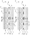
- FIGS. 5A-5D are schematic drawings depicting alternative configurations of a backlight system 50 a , which also is configured as an optical stack that combines a reflective barrier and slit structure with a lens array. These embodiments are comparable to the embodiments of FIGS. 4A-4D , except that in the examples of FIGS. 5A-5D , the convex side of the lens elements faces away from the barrier and slit structure and thus toward the viewing side. In other respects, the embodiments are generally comparable. With the orientation of FIGS. 5A-5D , the lens array substrate may be thick enough to space the lens elements at the desired distance from the barriers, which obviates the need for an additional spacer. Alternatively, the spacer 55 (see FIGS. 5C and 5D ) still may be used to achieve the desired separation in combination with a thin layer of glue.
- Reflective barriers as described in the various embodiments operate to recycle the light that does not pass through the slits, comparable to a DBEF film recycling polarized light, to boost the amount of light transmitted when placed on a viewing side of the backlight.
- Using a material with high reflectivity in the visible light range increases the amount of light that is recycled.
- Comparative measurements of a barrier and slit structure on a backlight show that a highly reflective material such as silver allows for over 80% of the light to be transmitted, as compared to a barrier made out of a black absorbing material which allows for only 35% of light to be transmitted.
- a Louvre film also only transmits about 35% of light from a backlight.
- a reflective barrier system therefore, is advantageous in achieving enhanced light transmission within a privacy display system.
- the barrier and slit structure is positioned on a viewing side of the backlight, and the lens array is positioned on a viewing side of the barrier and slit structure.
- the pitch of the lens array matches the pitch of the barrier and lens structure so that the optical effect is uniform across the backlight system. It may be desirable that there is a small difference in pitches between the lens array and the barrier and slit structure so that optical effect varies across the backlight system. This may be useful in large displays so that light from the outside of the display gets directed towards the center viewing region of the display.
- the ratio between lens pitch and barrier pitch for any neighbouring lens and barrier elements be in the range 0.9 ⁇ pitch ratio ⁇ 1.1.
- the lens elements For the lens elements to have strong focusing power, there is a large difference in refractive index between the lens array structure and the surrounding medium. Focusing power is strongest when the surrounding medium is air or a vacuum, i.e. the lens array should not be glued to the barrier and slit structure.
- the DBEF film or other brightness enhancement film may be placed within the optical stack as referenced above, and the DBEF may be most effective when positioned in between the viewing side surface of the BLU and the reflective barriers.
- FIG. 6 is a drawing depicting the light recycling function of the backlight system configured in accordance with embodiments of the present invention.
- FIG. 6 illustrates how a position of the lens elements relative to the barriers and slits affects the direction in which the light is collimated in a narrow or specific viewing angle range.
- the light is collimated on-axis or perpendicular to the lens array.
- the light is collimated off-axis relative to the lens array.
- the viewing angle direction of the collimated light can be selected based on the positioning of the lens array relative to the barrier and slit structure, and in particular based on the positioning of the centers of the lens element relative to the slits.
- the slits create apertures for the light to be transmitted through.
- the reflective barriers recycle light that does not pass through the slit apertures in a first pass from the backlight unit, and the lens array focuses or collimates the light that passes through the slit apertures in a particular direction.
- the direction in which the light is collimated is dependent on the position of the lens elements relative to the slits.
- FIG. 7 is a graph depicting performance of a conventional Louvre film versus a lens and reflective barrier system that is configured in accordance with embodiments of the present invention.
- the lens array and reflective barrier and slit structure are configured to provide on-axis collimation. Both configurations provide for a strong privacy mode with limited off-axis viewing at viewing angles beyond ⁇ 40° relative to center. However, within the on-axis desired viewing angle of ⁇ 40°, the lens and reflective barrier system of the present invention achieves substantially greater luminance as compared to Louvre films due to the light recycling that is performed by the lens and reflective barrier system as described above.
- FIGS. 8A and 8B The enhanced performance of the lens and reflective barrier system of the present invention further is illustrated in FIGS. 8A and 8B .
- FIG. 8A is a graph depicting luminance performance for the reflective barrier and slit structure of the present invention as compared to a conventional Louvre film and a conventional black card barrier system.
- FIG. 8B is a drawing depicting the light transmission using the reflective barrier and slit structure 54 of the present invention versus a conventional black card barrier system 80 .
- the graph shows that a reflective barrier and slit structure transmits over 80% of light from the BLU, as compared to 35% transmitted by a black card barrier equivalent and 35% transmitted by a Louvre film.
- a black card configuration would not be used in an actual device, but is employed herein as a black carrier equivalent for illustrative purpose to show the enhanced effects of the present invention.
- a black barrier would conventionally be made using an absorbing material such as a black emulsion.
- the enhancement occurs due to the light recycling performed by the reflective barrier and slit structure 54 , which is not performed by the black card barrier system 80 .
- the enhanced luminance using reflective barrier and slit structure 54 of the present invention results in a stronger private mode and a brighter public mode as compared to conventional configurations, as further detailed below.
- FIG. 9A is a schematic drawing depicting an exemplary display component 88 including a view angle control HHAN cell 90 , that is located between a front (viewing side) polarizer 92 and a rear (non-viewing side) polarizer 94 .
- the HHAN cell may 90 include the following components ordered from the viewing side as follows: a first electrode substrate 96 (which may be glass), a first electrode layer 98 (which may be indium tin oxide (ITO)), a first LC alignment layer 100 which may be a vertical alignment layer, a switchable doped liquid crystal LC layer 102 , a second alignment layer 104 which may be a planar alignment layer, a second electrode layer 106 (which also may be ITO), and a second electrode substrate 108 (which also may be glass).
- the light scattering function is enabled by doping the LC layer.
- FIG. 9A is representative of a HHAN cell, and variations and additional details are described in the '022 Application.
- FIG. 10 are graphs that include demonstrative results depicting a comparison of performance of a conventional display device configuration (“Traditional Solution”) versus performance of a display device configuration using a HHAN cell (“New Solution”). Such figure further corresponds to FIG. 12 of the '022 Application.
- Luminance is presented as a function of viewing angle for both a narrow angle viewing mode and a wide angle viewing mode.
- the conventional configuration used with respect to FIG. 10 is comparable to the configuration depicted in FIG. 1A , with the optical system including a combination of a Louvre film and a scattering layer.
- a HHAN cell may have somewhat lower luminance at wider angles in the wide angle view mode, which in practice does not correspond to any significant reduction in image quality to a viewer.
- the HHAN cell provides an enhanced narrow angle view mode with stronger privacy.
- the HHAN cell has lower transmission, i.e. stronger privacy, than the conventional configuration.
- the HHAN cell outperforms the conventional configuration in a significant manner in providing enhanced privacy in the narrow angle view mode.
- a display component of the present invention may include a switchable scattering device located on a viewing side of the lens array, wherein the switchable scattering device is switchable between a non-scattering state that collimates light from the backlight unit corresponding to a narrow viewing angle display mode, and a scattering state that scatters light from the backlight unit corresponding to a wide viewing angle display mode.
- the switchable scattering device may be a hydrodynamic hybrid nematic (HHAN) liquid crystal cell.
- the LCD layer 102 when doped with an ionic dopant, the LCD layer 102 can be switched into a scattering mode via the electro-hydrodynamic effect.
- the resultant hydrodynamic HAN LCD (HHAN) 90 can therefore be used to enhance the privacy of a collimated light source in one mode and then scatter that collimated light in a second mode.
- polarizers 92 and 94 are located on the viewing and non-viewing sides of the HHAN cell 90 . As depicted in FIG.
- a display component 110 further may include a first DBEF 112 in between the rear polarizer 94 and the HHAN cell 90 , which can boost brightness in the scattering mode.
- a display component 114 further may include a second DBEF 116 in between the front polarizer and the HHAN cell 90 , which can boost brightness even further in the scattering mode.
- the problem with the conventional Louvre film is that the Louvre film absorbs too much light, and thus the public mode is very dim when that light is scattered by the HHAN.
- the Louvre film is replaced by a lens and reflective barrier backlight system in accordance with embodiments of the present invention, then the private and public modes are substantially brighter as illustrated, for example, in the graphs of FIGS. 7 and 8 .
- the lens and reflective barrier backlight system can be incorporated into a display system to provide a strong privacy mode in combination with a substantially bright public mode as compared to conventional configurations.
- FIG. 11 is a schematic drawing depicting an exemplary display system 120 in accordance with embodiments of the present invention.
- the display system 120 includes a switchable scattering device 122 and an image panel 124 , positioned a viewing side of the backlight system 50 including a lens array and reflective barrier system 54 in accordance with embodiments of the present invention.
- FIG. 11 depicts an example using the embodiment of the optical stack arrangement of FIG. 5D , comparable principles apply to any of the embodiments of the backlight system which similarly may be incorporated into a display system.
- the switchable scattering device 122 may be switched between a narrow viewing angle mode for transmitting in a strong privacy mode, and a wide viewing angle mode for transmitting in a public mode.
- Various configurations of switchable scattering devices likewise are described in Applicant's '022 Application.
- FIG. 12 depicts a specific example of a display system 130 in accordance with embodiments of the present invention, in which the switchable scattering device is configured as the display component 114 of FIG. 9C (and similarly other display component embodiments such as FIGS. 9A and 9B may be employed).
- the switchable scattering device includes the switchable HHAN cell to provide switching between the private and public modes.
- the HHAN cell may have laminated onto it any combination of the rear linear polarizer, first DBEF, second DBEF, and front linear polarizer as illustrated in FIGS. 9A-9C .
- the front polarizer may not be needed, and the privacy enhancement of the HHAN cell also may be strong enough without the rear polarizer.
- DBEFs laminated onto the HHAN may be omitted to improve privacy performance at the cost of public mode brightness.
- the lens and reflective barrier backlight system provides a very bright private state, and the HHAN LCD strengthens the privacy.
- the HHAN is switched to a scattering mode that scatters the collimated light from the lens and reflective barrier backlight system to give a public mode with enhanced brightness as a result of the enhanced efficiency of the lens and reflective barrier backlight system.
- switchable scattering devices include a polymer dispersed liquid crystal (PDLC), and a hydrodynamic electrically controlled birefringence (ECB) or a hydrodynamic vertically aligned nematic (VAN) LC cell both of which can also enhance privacy as described in the '022 Application.
- PDLC polymer dispersed liquid crystal
- ECB hydrodynamic electrically controlled birefringence
- VAN hydrodynamic vertically aligned nematic
- FIG. 13 is a schematic drawing depicting operation of a display device 131 in accordance with embodiments of the present invention, including operation in both a private mode and a public mode.
- a backlight unit 132 emits light to a brightness enhancing film such as a DBEF 134 .
- the light passes through a lens array and reflective barrier system 136 , configured in accordance with any of the embodiments.
- the light then passes through a switchable scattering device such as an HHAN cell 138 , which also may be configured in accordance with any of the embodiments.
- the light subsequently illuminates a liquid crystal display (LCD) image panel 140 .
- LCD liquid crystal display
- the lens array and reflective barrier system 136 operates to transmit light predominantly in a narrow viewing angle range (e.g., on-axis), and with increased luminance in such viewing angle range as compared to conventional configurations which enables a strong private mode.
- a narrow viewing angle range e.g., on-axis
- the HHAN cell is switched to a narrow viewing angle mode so as to transmit light only within the narrow viewing angle range (e.g., on axis). Any residual off-axis light that may be transmitted through the lens array and reflective barrier system 136 is further attenuated by the HHAN cell, so as to enhance the viewing angle limitation of the private mode for enhanced privacy.
- the HHAN cell is switched to a wide viewing angle mode so as to transmit light within a broad viewing angle range.
- FIG. 14 illustrates an exemplary embodiment of a display system 131 a that operates comparably as the embodiment of FIG. 13 , and further illustrates that the HHAN cell alternatively can be located on the viewing side of the image panel 140 rather than on the non-viewing side as in FIG. 13 .
- the display component includes a backlight unit that emits light from a non-viewing side of the display component toward a viewing side of the display component; a barrier and slit structure located on a viewing side of the backlight unit, the barrier and slit structure comprising a plurality of opaque barrier regions interspersed with a plurality of transparent slit regions; and a lens array of lens elements located on a viewing side of the barrier and slit structure, with the lens elements being located in a separate plane relative to the barrier regions, wherein the barrier and slit structure and the lens array operate to transmit light from the backlight unit collimated in a limited viewing angle range.
- the display component may include one or more of the following features, either individually or in combination.
- the barrier regions are reflective barrier regions that recycle light emitted from the backlight unit.
- the barrier and slit structure comprises an enhanced spectral reflection film, and the slit regions are cut out from the film with the reflective barrier regions being the remaining film.
- the barrier and slit structure comprises a patterned reflective metal layer deposited on a transparent substrate.
- the patterned reflective metal layer is made of silver or aluminium.
- the barrier and slit structure further comprises a patterned light absorbing material deposited on a viewing side of the reflective barrier regions.
- the barrier regions and slit regions are parallel strips
- the lens array is a lenticular lens array including lens elements with a pitch to height ratio in the range of 5 ⁇ P/H ⁇ 2.
- the barrier and slit structure comprises a grid of barrier regions interspersed with aperture slit regions
- the lens array is a micro-lens array including lens elements with a pitch to height ratio in the range of 5 ⁇ P/H ⁇ 2.
- a pitch of the barrier and slit structure relates to a pitch of the lens array with a ratio of 0.9 ⁇ barrier:lens ⁇ 1.1.
- convex portions of lens elements of the lens array face toward the barrier and slit structure on the non-viewing side of the lens array.
- convex portions of lens elements of the lens array face away from the barrier and slit structure on the viewing side of the lens array.
- lens elements of the lens array are spaced apart from each other by transparent gaps.
- a light absorbing material is located between adjacent lens elements of the lens array.
- the display component further includes a spacer between the barrier and slit structure and the lens array to locate the lens array relative to the barrier and slit structure such that the separation between the lens apex and the barrier plane satisfies the range 5 ⁇ lens pitch/separation ⁇ 1.
- the display component further includes a brightness enhancement film located between the backlight unit and the barrier and slit structure.
- the display component further includes a switchable device located on a viewing side of the lens array, wherein the switchable device is switchable between a first state corresponding to a narrow viewing angle display mode, and a second state corresponding to a wide viewing angle display mode.
- the display component further includes a switchable scattering device located on a viewing side of the lens array, wherein the switchable scattering device is switchable between a non-scattering state that collimates light from the backlight unit or has no effect on the angular distribution of light from the backlight unit, corresponding to a narrow viewing angle display mode, and a scattering state that scatters light from the backlight unit corresponding to a wide viewing angle display mode.
- the switchable scattering device comprises a hydrodynamic hybrid nematic (HHAN) liquid crystal cell.
- HHAN hydrodynamic hybrid nematic
- the display component further includes a front polarizer located on a viewing side of the switchable scattering device and/or a rear polarizer located on a non-viewing side of the switchable scattering device; and a first brightness enhancement film located on a non-viewing side of the switchable scattering device and/or a second brightness enhancement film located on a viewing side of the switchable scattering device.
- Another aspect of the invention is a display system that is operable in a narrow viewing angle private mode and a wide viewing angle public mode, wherein the display system includes the display component according to any of the embodiments in combination with an image panel.
- the display system further includes a switchable scattering device located on a viewing side of the display component, wherein the switchable scattering device is switchable between a non-scattering state that collimates light from the backlight unit or has no effect on the angular distribution of light from the backlight unit, corresponding to the narrow viewing angle private mode, and a scattering state that scatters light from the backlight unit corresponding to the wide viewing angle public mode.
- the display system may include one or more of the following features, either individually or in combination.
- the switchable scattering device comprises a hydrodynamic hybrid nematic (HHAN) liquid crystal cell.
- HHAN hydrodynamic hybrid nematic
- the image panel is located on a viewing side of the switchable scattering device.
- the image panel is located on a non-viewing side of the switchable scattering device.
- the display system further includes a front polarizer located on a viewing side of the switchable scattering device and/or a rear polarizer located on a non-viewing side of the switchable scattering device; and a first brightness enhancement film located on a non-viewing side of the switchable scattering device and/or a second brightness enhancement film located on a viewing side of the switchable scattering device.
- Embodiments of the present invention are applicable to many display devices in which a strong narrow angle view private mode is desirable in additional to a wide angle view public mode.
- a strong private mode in particular is desirable for portable electronic display devices that are commonly used in a public setting. Examples of such devices include mobile phones including smartphones, personal digital assistants (PDAs), and tablet and laptop computers.
- PDAs personal digital assistants
- the strength of the privacy mode further is suitable for automotive applications, in which regulatory and general safety considerations require that a driver be unable to view moving image content being viewed by a passenger.
Landscapes
- Physics & Mathematics (AREA)
- General Physics & Mathematics (AREA)
- Nonlinear Science (AREA)
- Optics & Photonics (AREA)
- Chemical & Material Sciences (AREA)
- Crystallography & Structural Chemistry (AREA)
- Engineering & Computer Science (AREA)
- Mathematical Physics (AREA)
- Computer Hardware Design (AREA)
- Theoretical Computer Science (AREA)
- Optical Elements Other Than Lenses (AREA)
Abstract
A display component controls a viewing angle in a display system that achieves a strong private mode and enhanced brightness in the private and public modes as compared to conventional configurations. A display system that is operable in the private mode and the public mode includes the display component in combination with an image panel. The display component includes a backlight unit that emits light from a non-viewing side of the display component toward a viewing side of the display component; a barrier and slit structure located on a viewing side of the backlight unit, the barrier and slit structure comprising a plurality of opaque barrier regions interspersed with a plurality of transparent slit regions; and a lens array of lens elements located on a viewing side of the barrier and slit structure, with the lens elements being located in a separate plane relative to the barrier regions, wherein the barrier and slit structure and the lens array operate to transmit light from the backlight unit collimated in a limited viewing angle range.
Description
The present invention relates to a switchable privacy display system for use, for example, as an automotive display involving a backlight system that is switchable between a strong privacy mode and a bright public mode.
Displays in automotive vehicles are becoming more and more prominent. There is a push for larger displays to become a common feature in cars including entertainment displays for the passenger. The main obstacle preventing this from becoming a reality is privacy: by law in many jurisdictions and otherwise for general safety concerns, a driver must not be able to view moving image content on a display while driving. Accordingly, if a passenger is watching video content on the dashboard display, no light (or no variation of light level) is to be visible from the driver's position. Such result necessitates a strong privacy display, by which image content is visible only from within a specific and limited viewing angle range, and otherwise generally is not visible to a viewer outside of such viewing angle range.
Accordingly, attempts have been made to provide display systems with a strong privacy mode. FIG. 1A is a schematic drawing depicting a liquid crystal device (LCD) configuration 10 as is conventional in the art. FIG. 1B is a schematic drawing depicting an LCD configuration 20 that is representative of an improved privacy display designed by Applicant, as described in Applicant's application Ser. No. 15/981,022 filed on May 16, 2018 (the '022 Application), the contents of which are incorporated herein by reference. In the conventional configuration 10, a backlight 12 emits light 14 to a view angle control film 16, and the light subsequently illuminates a liquid crystal display (LCD) image panel 18. The view angle control film may be a Louvre film as are known in the art. As illustrated by the arrows schematically illustrating the light beams 14, although there is some attenuation of off-axis light by the view angle control film 16, the screening of the off-axis light often is insufficient to provide a full private mode, as some residual off-axis light is still transmitted to the image panel 18 and thus to the viewing side (as indicated by the smaller arrows pointing in the off-axis direction). Accordingly, a strong private mode is not achieved as an image corresponding to the residual off-axis light still may be perceived by an off-axis viewer. Accordingly, the conventional configuration of FIG. 1A results in a privacy mode that in particular does not meet the stringent requirements for automotive applications.
In the LCD device 20 of FIG. 1B that is described in the '022 Application, an additional switchable view angle control LCD 22 is incorporated into the device. The switchable view angle control LCD 22 may be a switchable scattering LCD that can be electrically switched between a first mode (Mode 1 in FIG. 1B ) and a second mode (Mode 2 in FIG. 1B ). In the first mode (Mode 1), the switchable view angle control LCD 22 performs a view angle restriction function without scattering light to provide a narrow angle viewing or private mode. Comparing Mode 1 to the conventional configuration, the off-axis light that might not be screened out by the view angle control film 16 is now blocked by the switchable view angle control LCD 22. In this manner, an enhanced privacy mode is achieved as compared to conventional configurations. In the second mode (Mode 2), the switchable view angle control LCD 22 operates to perform a light scattering function to achieve a wide angle viewing or public mode.
Accordingly, the configuration of the '022 Application of FIG. 1B addresses the automotive industry need for a display system that can switch between a strong private mode and a public mode. As described in the '022 Application, one way of achieving switchable privacy is to have a switchable scatterer positioned above a privacy optic such as the above-mentioned Louvre film. For example, the '022 Application describes a hydrodynamic hybrid-aligned nematic (HHAN) cell that, in a first mode, enhances the privacy of the display device, and in a second mode, scatters the previously collimated light off-axis to provide the public mode. One drawback of this system, however, is that the light efficiency is low and the public mode can appear dim because a Louvre film generally has a low light efficiency, transmitting only about 35% of the light from a backlight. When the HHAN cell is placed in the scattering mode, the already low level of collimated light is scattered out to wider angles, which can result in a dim public mode.
There is a need in the art, therefore, for an enhanced switchable privacy display system by which a strong private mode is achieved, and additionally light is transmitted with enhanced efficiency by the privacy optic so that in both the private mode and the public scattering mode, the display system does not appear too dim. The present invention pertains to such an enhanced switchable privacy display system. Such a display system is suitable for automotive displays in which such a strong private mode is required, although principles of the present invention may be applied to any suitable switchable privacy display system.
In exemplary embodiments, the enhanced light efficiency is achieved using a backlight system that includes a reflective barrier and slit structure, in combination with a lens array. The lens array may be configured as a lenticular lens array having half-cylindrical lens elements, or a micro-lens array including a two-dimensional array of micro-lens elements. The lens array and the reflective barrier and slit structure may be configured to have a matching pitch. A switchable view angle control device is positioned on a viewing side of the backlight system to improve the privacy mode while maintaining a bright public mode. In exemplary embodiments, the switchable scattering device is configured as a hydrodynamic hybrid-aligned nematic (HHAN) cell, which in a first mode enhances the privacy of the display device, and in a second mode scatters the previously collimated light off-axis to provide the public mode.
An aspect of the invention, therefore, is a display component for controlling a viewing angle in a display system that achieves a strong private mode and enhanced brightness in the private and public modes as compared to conventional configurations. Another aspect of the invention is a display system that is operable in a narrow viewing angle private mode and a wide viewing angle public mode, wherein the display system includes the display component according to any of the embodiments in combination with an image panel. The display component includes a backlight unit that emits light from a non-viewing side of the display component toward a viewing side of the display component; a barrier and slit structure located on a viewing side of the backlight unit, the barrier and slit structure comprising a plurality of opaque barrier regions interspersed with a plurality of transparent slit regions; and a lens array of lens elements located on a viewing side of the barrier and slit structure, with the lens elements being located in a separate plane relative to the barrier regions, wherein the barrier and slit structure and the lens array operate to transmit light from the backlight unit collimated in a limited viewing angle range.
In exemplary embodiments of the display component, the barrier regions are reflective barrier regions that recycle light emitted from the backlight unit. For example, the barrier and slit structure may be formed of an enhanced spectral reflection film, and the slit regions are cut out from the film with the reflective barrier regions being the remaining film. The barrier and slit structure may be a patterned reflective metal layer deposited on a transparent substrate. The display component further may include a switchable scattering device located on a viewing side of the lens array, wherein the switchable scattering device is switchable between a non-scattering state that collimates light from the backlight unit, or has substantially no effect on the angular distribution of light, corresponding to a narrow viewing angle display mode, and a scattering state that scatters light from the backlight unit corresponding to a wide viewing angle display mode. The switchable scattering device may be a hydrodynamic hybrid aligned nematic (HHAN) liquid crystal cell.
To the accomplishment of the foregoing and related ends, the invention, then, comprises the features hereinafter fully described and particularly pointed out in the claims. The following description and the annexed drawings set forth in detail certain illustrative embodiments of the invention. These embodiments are indicative, however, of but a few of the various ways in which the principles of the invention may be employed. Other objects, advantages and novel features of the invention will become apparent from the following detailed description of the invention when considered in conjunction with the drawings.
Embodiments of the present invention will now be described with reference to the drawings, wherein like reference numerals are used to refer to like elements throughout. It will be understood that the figures are not necessarily to scale.
The present invention pertains to an enhanced switchable privacy display system by which a strong private mode is achieved, and additionally light is transmitted with enhanced efficiency by the privacy optic so that in both the private mode and the public scattering mode, the display system does not appear too dim. Such a display system is suitable for automotive displays in which such a strong private mode is required, although principles of the present invention may be applied to any suitable switchable privacy display system.
In exemplary embodiments, the enhanced light efficiency is achieved using a backlight system that includes a reflective barrier and slit structure, in combination with a lens array. The lens array may be configured as a lenticular lens array having half-cylindrical lens elements, or a micro-lens array including a two-dimensional array of micro-lens elements. The lens and the reflective barrier and slit structure may be configured to have a matching pitch. A switchable scattering device may be positioned on a viewing side of the backlight system to enable switching between private and public modes. In exemplary embodiments, the switchable scattering device is configured as a hydrodynamic hybrid-aligned nematic (HHAN) cell to provide a strong private mode for automotive applications, which in a first mode enhances the privacy of the display device, and in a second mode scatters the previously collimated light off-axis to provide the public mode.
Reflective Barrier Structure and Lens Array
One method for achieving good privacy performance is to use a slit and barrier structure and a lens array. FIG. 2 is a schematic drawing depicting an exemplary barrier and slit structure 30 including a side view and a top view. As seen in the side view, the barrier and slit structure 30 may include opaque barrier regions 32 interspersed with transparent slit regions 34, with the opaque barrier regions being formed on a substrate 36 that is a transparent material such as glass to form the slits. A pitch P. barrier of the barrier and slit structure 30 is defined as the combined slit width and barrier width. A slit may have a width comparable to or the same as the width of an adjacent barrier, or the slit width may be less than or greater than the barrier width. It may be beneficial for the slit:barrier width ratio to be in the range of 20:80≤slit:barrier≤70:30, preferably in the range of 30:70≤slit:barrier≤60:40 or in the range of 40:60≤slit:barrier≤50:50. As seen in the top view portion of FIG. 2 , in a barrier and slit configuration 30 a the barriers can be arranged in parallel barrier strips 32 a with parallel slits 34 a interspersed between the barriers (1D version). Alternatively, in a barrier and slit configuration 30 b the barriers can be arranged as a barrier grid 32 b with apertures 34 b interspersed within the grid acting as the slits (2D version). The apertures may be any shape such as square, rectangular, circular or elliptical. The barrier and slit pitch may vary across the structure, or the pitch may be consistent across the structure. The barrier and slit structure may be a film whereby the slits have been cut out, or the structure may have been patterned onto a substrate, with variations described in more detail below.
As seen in the top views, the lens arrays 40 and 41 may be configured as a lenticular lens array 40 a or 41 a (1D version) configured as strips of lens elements 42 a formed as near half-cylinder lens elements, which in the configuration of lens array 41 a further includes gaps 43 a oriented as parallel strips between the lens elements 42 a. Alternatively, the lens arrays 40 and 41 may be configured as a micro-lens array 40 b or 41 b (2D version) configured as a two-dimensional array of near half sphere lens elements 42 b, which in the configuration of lens array 41 b further includes gaps 43 b oriented as a grid of gaps running between the lens elements 42 b.
In exemplary embodiments of the present invention, an enhanced backlight system may include barrier and slit structure combined with a lens array to form an optical stack that may be used to provide for enhanced private and public viewing modes in a switchable privacy display system. Generally, a 1D version of barrier and slit structure 30 a (parallel strip barriers/slits) may be combined with a lenticular lens array 40 a/41 a (half-cylinder lens elements). Similarly, a 2D version of barrier and slit structure 30 b (grid barrier with aperture slits) may be combined with a micro lens array 40 b/41 b (half-spherical lens elements).
An aspect of the invention, therefore, is a display component for controlling a viewing angle in a display system that achieves a strong private mode and enhanced brightness in the private and public modes as compared to conventional configurations. The display component includes a backlight unit that emits light from a non-viewing side of the display component toward a viewing side of the display component; a barrier and slit structure located on a viewing side of the backlight unit, the barrier and slit structure comprising a plurality of opaque barrier regions interspersed with a plurality of transparent slit regions; and a lens array of lens elements located on a viewing side of the barrier and slit structure, with the lens elements being located in a separate plane relative to the barrier regions, wherein the barrier and slit structure and the lens array operate to transmit light from the backlight unit collimated in a limited viewing angle range. In exemplary embodiments of the display component, the barrier regions are reflective barrier regions that recycle light emitted from the backlight unit.
In the various embodiments of FIGS. 4A-4D , a backlight system 50 is configured as an optical stack that includes a lens array 52 that may be configured in accordance with any of the configurations as described with respect to FIGS. 3A and 3B . The lens array 52 is deposited on a transparent substrate 53, which may be glass or other suitable transparent material usable in displays. With the orientation of the convex side of the lens elements facing toward the barrier and slit structures, an additional substrate 53 gives the lens array desirable rigidity. The lens array 52 is positioned on a viewing side of a barrier and slit structure 54 (a, b, c, or d), with the differences in such structures being described in more detail blow. A spacer 55 may be employed to locate the lens array 52 at an optimal distance relative to the barrier and slit structure. The barrier and slit structure 54 (a, b, c, or d) may be deposited on the viewing side of a brightness enhancement film 56, such as a dual brightness enhancement film (DBEF). The spacer, barrier and slit configuration, and DBEF may be adhered to each other using a suitable optically transparent glue 57. The combination of spacer and glue layer is chosen as optimal for any particular application, and generally glue layer may be very thin, and all glue layers preferably have a refractive index matching adjacent substrates or layers.
The total separation “s” (see FIG. 4A ) between the apex of the lens array and the plane of the barrier and slit structure may be optimized depending on the pitch and height of the lens elements. Accordingly, the lens elements of the lens array are located in a separate plane relative to the barrier regions of the barrier and slit structure. In general, it may be desirable for the ratio of the pitch P to the separation s to be in the range of 5≥P/s≥1. More preferably, the ratio is in the range of 3.5≥P/s≥1.2 or in the range of 2.7≥P/s≥1.5. The spacing between the lens elements may be filled with a low refractive index medium 58, and power of the lenses is maximized if the low refractive index medium is air or a vacuum. The optical stack 50 further includes a backlight unit 59 (BLU) located on a non-viewing side of the optical stack to act as a light source that emits light from the non-viewing side of the optical stack toward the viewing side of the optical stack.
In exemplary embodiments, the barrier and slit structure includes a reflective material that forms the barrier regions, which may be configured in a variety of ways. In the embodiment of FIG. 4A , the barrier and slit structure 54 a is formed from a reflective film, such as for example an enhanced spectral reflection (ESR) film. When employing such a film, slits 62 may be cut out from the film with the barrier regions 60 being the remaining film, or the film may be manufactured to contain the slits between the barriers. In the embodiment of FIG. 4B , the barrier and slit structure 54 b is configured to have reflective metal barrier regions 64, such as aluminium or silver barriers. The reflective barrier and slit structure 54 b may be fabricated by depositing a reflective metal material such as aluminium or silver onto a transparent substrate 66 to form a patterned metal layer on the substrate with the slits 62 positioned between the metal barrier regions. The substrate 66 may be an optically transparent material such as glass. In the embodiment of FIG. 4C , the barrier and slit structure 54 c is formed using silver to form patterned reflective metal barrier regions 68. When employing silver barriers, it is beneficial first to deposit an additional patterned adhesion layer 70 on the substrate 66 to enable stronger adhesion of the patterned silver barrier regions 68 to the substrate. This additional patterned adhesion layer 70 may be an optically thin layer of chrome. As shown in the embodiment of FIG. 4D , to reduce reflections off the top surface of the reflective barriers, a patterned light absorbing material layer 72 may be deposited on the viewing side of reflective barrier regions 74, with the reflective barrier regions 74 being configured according to any of the embodiments. The absorbing material of the light patterned absorbing layer 72 may be a black mask, a black emulsion, black chrome, or any other suitable low reflection material. In the various embodiments, the barrier-slit pattern also may be created by etching away the desired areas of reflective material via photolithography.
Reflective barriers as described in the various embodiments operate to recycle the light that does not pass through the slits, comparable to a DBEF film recycling polarized light, to boost the amount of light transmitted when placed on a viewing side of the backlight. Using a material with high reflectivity in the visible light range increases the amount of light that is recycled. Comparative measurements of a barrier and slit structure on a backlight show that a highly reflective material such as silver allows for over 80% of the light to be transmitted, as compared to a barrier made out of a black absorbing material which allows for only 35% of light to be transmitted. A Louvre film also only transmits about 35% of light from a backlight. A reflective barrier system, therefore, is advantageous in achieving enhanced light transmission within a privacy display system.
As referenced above, in a lens array and reflective barrier backlight system, the barrier and slit structure is positioned on a viewing side of the backlight, and the lens array is positioned on a viewing side of the barrier and slit structure. It may be desirable that the pitch of the lens array matches the pitch of the barrier and lens structure so that the optical effect is uniform across the backlight system. It may be desirable that there is a small difference in pitches between the lens array and the barrier and slit structure so that optical effect varies across the backlight system. This may be useful in large displays so that light from the outside of the display gets directed towards the center viewing region of the display. In general, it is desired that the ratio between lens pitch and barrier pitch for any neighbouring lens and barrier elements be in the range 0.9≤pitch ratio≤1.1. For the lens elements to have strong focusing power, there is a large difference in refractive index between the lens array structure and the surrounding medium. Focusing power is strongest when the surrounding medium is air or a vacuum, i.e. the lens array should not be glued to the barrier and slit structure. The DBEF film or other brightness enhancement film may be placed within the optical stack as referenced above, and the DBEF may be most effective when positioned in between the viewing side surface of the BLU and the reflective barriers.
Accordingly, with a lens array and reflective barrier system positioned on the viewing side of a backlight unit, the slits create apertures for the light to be transmitted through. The reflective barriers recycle light that does not pass through the slit apertures in a first pass from the backlight unit, and the lens array focuses or collimates the light that passes through the slit apertures in a particular direction. For a near half-cylinder lenticular or half-sphere micro lens array, the direction in which the light is collimated is dependent on the position of the lens elements relative to the slits. If the center of a lens element is positioned above the center of a slit, then the light will be collimated in a direction perpendicular to the surface of the lens array which corresponds to on-axis collimation (FIG. 6 , left portion). If the center of a lens element is not directly above the center of a slit, then the collimation direction will not be perpendicular to the surface of the lens array which corresponds to off-axis collimation (FIG. 6 , right portion). Such operation can be used to create a display system with either symmetric privacy or asymmetric privacy modes. Asymmetric privacy may also be achieved by using variations in the shape of the lens elements rather than half cylinder or half-sphere lens elements.
The enhanced performance of the lens and reflective barrier system of the present invention further is illustrated in FIGS. 8A and 8B . In particular, FIG. 8A is a graph depicting luminance performance for the reflective barrier and slit structure of the present invention as compared to a conventional Louvre film and a conventional black card barrier system. FIG. 8B is a drawing depicting the light transmission using the reflective barrier and slit structure 54 of the present invention versus a conventional black card barrier system 80. The graph shows that a reflective barrier and slit structure transmits over 80% of light from the BLU, as compared to 35% transmitted by a black card barrier equivalent and 35% transmitted by a Louvre film. In practice, a black card configuration would not be used in an actual device, but is employed herein as a black carrier equivalent for illustrative purpose to show the enhanced effects of the present invention. In devices, a black barrier would conventionally be made using an absorbing material such as a black emulsion. As shown in FIG. 8B , the enhancement occurs due to the light recycling performed by the reflective barrier and slit structure 54, which is not performed by the black card barrier system 80. The enhanced luminance using reflective barrier and slit structure 54 of the present invention results in a stronger private mode and a brighter public mode as compared to conventional configurations, as further detailed below.
Lens and Reflective Barrier Combined With HHAN
As described in Applicant's '022 Application, which as referenced above is incorporated herein by reference, a hydrodynamic hybrid aligned nematic (HHAN) LCD cell can be used to provide increased privacy in a display device and to perform a light scattering function. FIG. 9A is a schematic drawing depicting an exemplary display component 88 including a view angle control HHAN cell 90, that is located between a front (viewing side) polarizer 92 and a rear (non-viewing side) polarizer 94. In general, the HHAN cell may 90 include the following components ordered from the viewing side as follows: a first electrode substrate 96 (which may be glass), a first electrode layer 98 (which may be indium tin oxide (ITO)), a first LC alignment layer 100 which may be a vertical alignment layer, a switchable doped liquid crystal LC layer 102, a second alignment layer 104 which may be a planar alignment layer, a second electrode layer 106 (which also may be ITO), and a second electrode substrate 108 (which also may be glass). The light scattering function is enabled by doping the LC layer. The configuration of FIG. 9A is representative of a HHAN cell, and variations and additional details are described in the '022 Application.
A display component of the present invention, therefore, further may include a switchable scattering device located on a viewing side of the lens array, wherein the switchable scattering device is switchable between a non-scattering state that collimates light from the backlight unit corresponding to a narrow viewing angle display mode, and a scattering state that scatters light from the backlight unit corresponding to a wide viewing angle display mode. The switchable scattering device may be a hydrodynamic hybrid nematic (HHAN) liquid crystal cell.
Referring back to FIG. 9A , when doped with an ionic dopant, the LCD layer 102 can be switched into a scattering mode via the electro-hydrodynamic effect. The resultant hydrodynamic HAN LCD (HHAN) 90 can therefore be used to enhance the privacy of a collimated light source in one mode and then scatter that collimated light in a second mode. As illustrated in FIG. 9A , to operate in a privacy mode using an HHAN cell, polarizers 92 and 94 are located on the viewing and non-viewing sides of the HHAN cell 90. As depicted in FIG. 9B , a display component 110 further may include a first DBEF 112 in between the rear polarizer 94 and the HHAN cell 90, which can boost brightness in the scattering mode. In addition, as depicted in FIG. 9C , a display component 114 further may include a second DBEF 116 in between the front polarizer and the HHAN cell 90, which can boost brightness even further in the scattering mode.
As detailed above, the problem with the conventional Louvre film is that the Louvre film absorbs too much light, and thus the public mode is very dim when that light is scattered by the HHAN. When the Louvre film is replaced by a lens and reflective barrier backlight system in accordance with embodiments of the present invention, then the private and public modes are substantially brighter as illustrated, for example, in the graphs of FIGS. 7 and 8 . Accordingly, the lens and reflective barrier backlight system can be incorporated into a display system to provide a strong privacy mode in combination with a substantially bright public mode as compared to conventional configurations.
In both the private and public modes, the lens array and reflective barrier system 136 operates to transmit light predominantly in a narrow viewing angle range (e.g., on-axis), and with increased luminance in such viewing angle range as compared to conventional configurations which enables a strong private mode. When operating in such private mode, the HHAN cell is switched to a narrow viewing angle mode so as to transmit light only within the narrow viewing angle range (e.g., on axis). Any residual off-axis light that may be transmitted through the lens array and reflective barrier system 136 is further attenuated by the HHAN cell, so as to enhance the viewing angle limitation of the private mode for enhanced privacy. When operating in the public mode, the HHAN cell is switched to a wide viewing angle mode so as to transmit light within a broad viewing angle range. Furthermore, because of the enhanced brightness of light transmitted by the lens array and reflective barrier system 136 as compared to conventional configurations, the public mode appears brighter as compared to conventional configurations. FIG. 14 illustrates an exemplary embodiment of a display system 131 a that operates comparably as the embodiment of FIG. 13 , and further illustrates that the HHAN cell alternatively can be located on the viewing side of the image panel 140 rather than on the non-viewing side as in FIG. 13 .
An aspect of the invention, therefore, is a display component for controlling a viewing angle in a display system that achieves a strong private mode and enhanced brightness in the private and public modes as compared to conventional configurations. In exemplary embodiments, the display component includes a backlight unit that emits light from a non-viewing side of the display component toward a viewing side of the display component; a barrier and slit structure located on a viewing side of the backlight unit, the barrier and slit structure comprising a plurality of opaque barrier regions interspersed with a plurality of transparent slit regions; and a lens array of lens elements located on a viewing side of the barrier and slit structure, with the lens elements being located in a separate plane relative to the barrier regions, wherein the barrier and slit structure and the lens array operate to transmit light from the backlight unit collimated in a limited viewing angle range. The display component may include one or more of the following features, either individually or in combination.
In an exemplary embodiment of the display component, the barrier regions are reflective barrier regions that recycle light emitted from the backlight unit.
In an exemplary embodiment of the display component, the barrier and slit structure comprises an enhanced spectral reflection film, and the slit regions are cut out from the film with the reflective barrier regions being the remaining film.
In an exemplary embodiment of the display component, the barrier and slit structure comprises a patterned reflective metal layer deposited on a transparent substrate.
In an exemplary embodiment of the display component, the patterned reflective metal layer is made of silver or aluminium.
In an exemplary embodiment of the display component, the barrier and slit structure further comprises a patterned light absorbing material deposited on a viewing side of the reflective barrier regions.
In an exemplary embodiment of the display component, the barrier regions and slit regions are parallel strips, and the lens array is a lenticular lens array including lens elements with a pitch to height ratio in the range of 5≥P/H≥2.
In an exemplary embodiment of the display component, the barrier and slit structure comprises a grid of barrier regions interspersed with aperture slit regions, and the lens array is a micro-lens array including lens elements with a pitch to height ratio in the range of 5≥P/H≥2.
In an exemplary embodiment of the display component, a pitch of the barrier and slit structure relates to a pitch of the lens array with a ratio of 0.9≤barrier:lens≤1.1.
In an exemplary embodiment of the display component, convex portions of lens elements of the lens array face toward the barrier and slit structure on the non-viewing side of the lens array.
In an exemplary embodiment of the display component, convex portions of lens elements of the lens array face away from the barrier and slit structure on the viewing side of the lens array.
In an exemplary embodiment of the display component, lens elements of the lens array are spaced apart from each other by transparent gaps.
In an exemplary embodiment of the display component, a light absorbing material is located between adjacent lens elements of the lens array.
In an exemplary embodiment of the display component, the display component further includes a spacer between the barrier and slit structure and the lens array to locate the lens array relative to the barrier and slit structure such that the separation between the lens apex and the barrier plane satisfies the range 5≥lens pitch/separation≥1.
In an exemplary embodiment of the display component, the display component further includes a brightness enhancement film located between the backlight unit and the barrier and slit structure.
In an exemplary embodiment of the display component, the display component further includes a switchable device located on a viewing side of the lens array, wherein the switchable device is switchable between a first state corresponding to a narrow viewing angle display mode, and a second state corresponding to a wide viewing angle display mode.
In an exemplary embodiment of the display component, the display component further includes a switchable scattering device located on a viewing side of the lens array, wherein the switchable scattering device is switchable between a non-scattering state that collimates light from the backlight unit or has no effect on the angular distribution of light from the backlight unit, corresponding to a narrow viewing angle display mode, and a scattering state that scatters light from the backlight unit corresponding to a wide viewing angle display mode.
In an exemplary embodiment of the display component, the switchable scattering device comprises a hydrodynamic hybrid nematic (HHAN) liquid crystal cell.
In an exemplary embodiment of the display component, the display component further includes a front polarizer located on a viewing side of the switchable scattering device and/or a rear polarizer located on a non-viewing side of the switchable scattering device; and a first brightness enhancement film located on a non-viewing side of the switchable scattering device and/or a second brightness enhancement film located on a viewing side of the switchable scattering device.
Another aspect of the invention is a display system that is operable in a narrow viewing angle private mode and a wide viewing angle public mode, wherein the display system includes the display component according to any of the embodiments in combination with an image panel. The display system further includes a switchable scattering device located on a viewing side of the display component, wherein the switchable scattering device is switchable between a non-scattering state that collimates light from the backlight unit or has no effect on the angular distribution of light from the backlight unit, corresponding to the narrow viewing angle private mode, and a scattering state that scatters light from the backlight unit corresponding to the wide viewing angle public mode. The display system may include one or more of the following features, either individually or in combination.
In an exemplary embodiment of the display system, the switchable scattering device comprises a hydrodynamic hybrid nematic (HHAN) liquid crystal cell.
In an exemplary embodiment of the display system, the image panel is located on a viewing side of the switchable scattering device.
In an exemplary embodiment of the display system, the image panel is located on a non-viewing side of the switchable scattering device.
In an exemplary embodiment of the display system, the display system further includes a front polarizer located on a viewing side of the switchable scattering device and/or a rear polarizer located on a non-viewing side of the switchable scattering device; and a first brightness enhancement film located on a non-viewing side of the switchable scattering device and/or a second brightness enhancement film located on a viewing side of the switchable scattering device.
Although the invention has been shown and described with respect to a certain embodiment or embodiments, it is obvious that equivalent alterations and modifications will occur to others skilled in the art upon the reading and understanding of this specification and the annexed drawings. In particular regard to the various functions performed by the above described elements (components, assemblies, devices, compositions, etc.), the terms (including a reference to a “means”) used to describe such elements are intended to correspond, unless otherwise indicated, to any element which performs the specified function of the described element (i.e., that is functionally equivalent), even though not structurally equivalent to the disclosed structure which performs the function in the herein illustrated exemplary embodiment or embodiments of the invention. In addition, while a particular feature of the invention may have been described above with respect to only one or more of several illustrated embodiments, such feature may be combined with one or more other features of the other embodiments, as may be desired and advantageous for any given or particular application.
Embodiments of the present invention are applicable to many display devices in which a strong narrow angle view private mode is desirable in additional to a wide angle view public mode. A strong private mode in particular is desirable for portable electronic display devices that are commonly used in a public setting. Examples of such devices include mobile phones including smartphones, personal digital assistants (PDAs), and tablet and laptop computers. The strength of the privacy mode further is suitable for automotive applications, in which regulatory and general safety considerations require that a driver be unable to view moving image content being viewed by a passenger.
- 10—conventional LCD configuration
- 12—backlight
- 14—light
- 16—view angle control film
- 18—LCD image panel
- 20—enhanced LCD configuration
- 22—view angle control LCD
- 30—barrier and slit structure
- 30 a—barrier and slit configuration
- 30 b—barrier and slit configuration
- 32—opaque barrier regions
- 32 a—parallel barrier strips
- 32 b—barrier grid
- 34—transparent slit regions
- 34 a—parallel slits
- 34 b—aperture slits
- 36—substrate
- 40—lens array
- 40 a—lenticular lens array
- 40 b—micro-lens array
- 41—lens array with gaps
- 41 a—lenticular lens array
- 41 b—micro-lens array
- 42—lens elements
- 42 a—strips of lens elements
- 42 b—two-dimensional array of lens elements
- 43—gaps
- 43 a—gaps
- 43 b—gaps
- 44—transparent substrate
- 45—light absorbing coating
- 50—backlight system
- 50 a—backlight system
- 52—lens array
- 53—transparent substrate
- 54—barrier and slit structure
- 54 a—barrier and slit structure
- 54 b—barrier and slit structure
- 54 c—barrier and slit structure
- 55—spacer
- 57—optically transparent glue
- 59—backlight unit
- 62—slits
- 64—reflective metal barrier region
- 66—transparent substrate
- 68—patterned reflective metal barrier regions
- 70—patterned adhesion layer
- 72—patterned light absorbing material layer
- 74—reflective barrier regions
- 80—conventional black card barrier system
- 88—exemplary display component
- 90—view angle control HHAN cell
- 92—front (viewing side) polarizer
- 94—rear (non-viewing) side polarizer
- 96—first electrode substrate
- 98—first electrode layer
- 100—first LC alignment layer
- 102—switchable doped liquid crystal LC layer
- 104—second alignment layer
- 106—second electrode layer
- 108—second electrode substrate
- 110—display component
- 112—first DBEF
- 114—display component
- 116—second DBEF
- 120—display system
- 122—scattering device
- 124—image panel
- 130—display system
- 131—display system
- 131 a—display system
- 132—backlight unit
- 134—DBEF
- 136—lens array and reflective barrier system
- 138—HHAN cell
- 140—LCD image panel
Claims (18)
1. A display component for controlling a viewing angle in a display system, the display component comprising:
a backlight unit that emits light from a non-viewing side of the display component toward a viewing side of the display component;
a barrier and slit structure located on a viewing side of the backlight unit, the barrier and slit structure comprising a plurality of opaque barrier regions interspersed with a plurality of transparent slit regions; and
a lens array of lens elements located on a viewing side of the barrier and slit structure, with the lens elements being located in a separate plane relative to the barrier regions, wherein the barrier and slit structure and the lens array operate to transmit light from the backlight unit collimated in a limited viewing angle range;
wherein the barrier regions are reflective barrier regions that recycle light emitted from the backlight unit, and the barrier and slit structure comprises a patterned reflective metal layer deposited on a transparent substrate.
2. The display component of claim 1 , wherein the barrier and slit structure further comprises a patterned light absorbing material deposited on a viewing side of the reflective barrier regions.
3. The display component of claim 1 , wherein the barrier regions and slit regions are parallel strips, and the lens array is a lenticular lens array including lens elements with a pitch to height ratio in the range of 5≥P/H≥2.
4. The display component of claim 1 , wherein the barrier and slit structure comprises a grid of barrier regions interspersed with aperture slit regions, and the lens array is a micro-lens array including lens elements with a pitch to height ratio in the range of 5≥P/H≥2.
5. The display component of claim 1 , wherein a pitch of the barrier and slit structure relates to a pitch of the lens array with a ratio of 0.9≤barrier:lens≤1.1.
6. The display component of claim 1 , wherein convex portions of lens elements of the lens array face toward the barrier and slit structure on the non-viewing side of the lens array.
7. The display component of claim 1 , wherein convex portions of lens elements of the lens array face away from the barrier and slit structure on the viewing side of the lens array.
8. The display component of claim 1 , wherein lens elements of the lens array are spaced apart from each other by transparent gaps.
9. The display component of claim 1 , wherein a light absorbing material is located between adjacent lens elements of the lens array.
10. The display component of claim 1 , further comprising a spacer between the barrier and slit structure and the lens array to locate the lens array relative to the barrier and slit structure such that the separation between the lens apex and the barrier plane satisfies the range 5≥lens pitch/separation≥1.
11. A display component for controlling a viewing angle in a display system, the display component comprising:
a backlight unit that emits light from a non-viewing side of the display component toward a viewing side of the display component;
a barrier and slit structure located on a viewing side of the backlight unit, the barrier and slit structure comprising a plurality of opaque barrier regions interspersed with a plurality of transparent slit regions;
a lens array of lens elements located on a viewing side of the barrier and slit structure, with the lens elements being located in a separate plane relative to the barrier regions, wherein the barrier and slit structure and the lens array operate to transmit light from the backlight unit collimated in a limited viewing angle range; and
a switchable device located on a viewing side of the lens array, wherein the switchable device is switchable between a first state corresponding to a narrow viewing angle display mode, and a second state corresponding to a wide viewing angle display mode.
12. A display component for controlling a viewing angle in a display system, the display component comprising:
a backlight unit that emits light from a non-viewing side of the display component toward a viewing side of the display component;
a barrier and slit structure located on a viewing side of the backlight unit, the barrier and slit structure comprising a plurality of opaque barrier regions interspersed with a plurality of transparent slit regions;
a lens array of lens elements located on a viewing side of the barrier and slit structure, with the lens elements being located in a separate plane relative to the barrier regions, wherein the barrier and slit structure and the lens array operate to transmit light from the backlight unit collimated in a limited viewing angle rage; and
a switchable scattering device located on a viewing side of the lens array, wherein the switchable scattering device is switchable between a non-scattering state that collimates light from the backlight unit or has no effect on the angular distribution of light from the backlight unit, corresponding to a narrow viewing angle display mode, and a scattering state that scatters light from the backlight unit corresponding to a wide viewing angle display mode.
13. The display component of claim 12 , wherein the switchable scattering device comprises a hydrodynamic hybrid nematic (HHAN) liquid crystal cell.
14. A display system that is operable in a narrowing viewing angle private mode and a wide viewing angle public mode comprising:
the display component according to claim 1 ;
a switchable scattering device located on a viewing side of the display component, wherein the switchable scattering device is switchable between a non-scattering state that collimates light from the backlight unit or has no effect on the angular distribution of light from the backlight unit, corresponding to the narrow viewing angle private mode, and a scattering state that scatters light from the backlight unit corresponding to the wide viewing angle public mode; and
an image panel located on a viewing side of the display component.
15. The display system of claim 14 , wherein the switchable scattering device comprises a hydrodynamic hybrid nematic (HHAN) liquid crystal cell.
16. The system device of claim 14 , wherein the image panel is located on a viewing side of the switchable scattering device.
17. The display system of claim 14 , wherein the image panel is located on a non-viewing side of the switchable scattering device.
18. The display system of claim 14 , further comprising:
a front polarizer located on a viewing side of the switchable scattering device and/or a rear polarizer located on a non-viewing side of the switchable scattering device; and
a first brightness enhancement film located on a non-viewing side of the switchable scattering device and/or a second brightness enhancement film located on a viewing side of the switchable scattering device.
Priority Applications (1)
| Application Number | Priority Date | Filing Date | Title |
|---|---|---|---|
| US16/263,295 US10663776B1 (en) | 2019-01-31 | 2019-01-31 | Enhanced privacy switchable backlight system |
Applications Claiming Priority (1)
| Application Number | Priority Date | Filing Date | Title |
|---|---|---|---|
| US16/263,295 US10663776B1 (en) | 2019-01-31 | 2019-01-31 | Enhanced privacy switchable backlight system |
Publications (1)
| Publication Number | Publication Date |
|---|---|
| US10663776B1 true US10663776B1 (en) | 2020-05-26 |
Family
ID=70774805
Family Applications (1)
| Application Number | Title | Priority Date | Filing Date |
|---|---|---|---|
| US16/263,295 Active US10663776B1 (en) | 2019-01-31 | 2019-01-31 | Enhanced privacy switchable backlight system |
Country Status (1)
| Country | Link |
|---|---|
| US (1) | US10663776B1 (en) |
Cited By (11)
| Publication number | Priority date | Publication date | Assignee | Title |
|---|---|---|---|---|
| US11024681B2 (en) * | 2019-08-15 | 2021-06-01 | Sharp Kabushiki Kaisha | Parallax optics for top emitting electroluminescent displays |
| US11054701B1 (en) * | 2020-02-18 | 2021-07-06 | Sioptica Gmbh | Illumination device for a screen for a free and a restricted viewing mode |
| WO2021238345A1 (en) * | 2020-05-27 | 2021-12-02 | 华为技术有限公司 | Viewing angle controllable module, viewing angle control method and electronic device |
| WO2022027580A1 (en) * | 2020-08-06 | 2022-02-10 | 无锡威峰科技股份有限公司 | Display plasma module and display device |
| WO2022152603A1 (en) | 2021-01-18 | 2022-07-21 | Volkswagen Aktiengesellschaft | Display device and motor vehicle having a display device |
| US20220284255A1 (en) * | 2020-01-07 | 2022-09-08 | Capital One Services, Llc | Providing Alerts via a Color Changing Transaction Card |
| CN116259238A (en) * | 2023-03-16 | 2023-06-13 | 上海天马微电子有限公司 | Backlight module and display device |
| US11714223B2 (en) * | 2019-12-05 | 2023-08-01 | Lumus Ltd. | Light-guide optical element employing complementary coated partial reflectors, and light-guide optical element having reduced light scattering |
| US20240138240A1 (en) * | 2022-10-18 | 2024-04-25 | Lg Display Co., Ltd. | Light-emitting display device |
| US20240272462A1 (en) * | 2023-02-09 | 2024-08-15 | Innolux Corporation | Electronic device |
| US20250008074A1 (en) * | 2023-06-29 | 2025-01-02 | Samsung Electronics Co., Ltd. | Light field display apparatus |
Citations (2)
| Publication number | Priority date | Publication date | Assignee | Title |
|---|---|---|---|---|
| US20140361990A1 (en) * | 2012-01-26 | 2014-12-11 | Seereal Technologies S.A. | Display with observer tracking |
| US9881531B2 (en) | 2014-02-17 | 2018-01-30 | Sioptica Gmbh | Switchable lighting device and use thereof |
-
2019
- 2019-01-31 US US16/263,295 patent/US10663776B1/en active Active
Patent Citations (2)
| Publication number | Priority date | Publication date | Assignee | Title |
|---|---|---|---|---|
| US20140361990A1 (en) * | 2012-01-26 | 2014-12-11 | Seereal Technologies S.A. | Display with observer tracking |
| US9881531B2 (en) | 2014-02-17 | 2018-01-30 | Sioptica Gmbh | Switchable lighting device and use thereof |
Non-Patent Citations (1)
| Title |
|---|
| Jae-Won Huh et al.: "Ion-doped liquid-crystal cell with low opaque-state specular transmittance based on electro-hydrodynamic effect", Dyes and Pigments 150, pp. 16-20, 2018, https://doi.org/10.1016/j.dyepig.2017.11.001. |
Cited By (18)
| Publication number | Priority date | Publication date | Assignee | Title |
|---|---|---|---|---|
| US11024681B2 (en) * | 2019-08-15 | 2021-06-01 | Sharp Kabushiki Kaisha | Parallax optics for top emitting electroluminescent displays |
| US11714223B2 (en) * | 2019-12-05 | 2023-08-01 | Lumus Ltd. | Light-guide optical element employing complementary coated partial reflectors, and light-guide optical element having reduced light scattering |
| US12007596B2 (en) * | 2019-12-05 | 2024-06-11 | Lumus Ltd. | Light-guide optical element employing complementary coated partial reflectors, and light-guide optical element having reduced light scattering |
| US20220284255A1 (en) * | 2020-01-07 | 2022-09-08 | Capital One Services, Llc | Providing Alerts via a Color Changing Transaction Card |
| US11054701B1 (en) * | 2020-02-18 | 2021-07-06 | Sioptica Gmbh | Illumination device for a screen for a free and a restricted viewing mode |
| WO2021238345A1 (en) * | 2020-05-27 | 2021-12-02 | 华为技术有限公司 | Viewing angle controllable module, viewing angle control method and electronic device |
| WO2022027580A1 (en) * | 2020-08-06 | 2022-02-10 | 无锡威峰科技股份有限公司 | Display plasma module and display device |
| WO2022152603A1 (en) | 2021-01-18 | 2022-07-21 | Volkswagen Aktiengesellschaft | Display device and motor vehicle having a display device |
| DE102021200422A1 (en) | 2021-01-18 | 2022-07-21 | Volkswagen Aktiengesellschaft | Display device and motor vehicle comprising a display device |
| DE102021200422B4 (en) | 2021-01-18 | 2025-02-13 | Volkswagen Aktiengesellschaft | Display device and motor vehicle comprising a display device |
| US20240138240A1 (en) * | 2022-10-18 | 2024-04-25 | Lg Display Co., Ltd. | Light-emitting display device |
| JP2024060574A (en) * | 2022-10-19 | 2024-05-02 | エルジー ディスプレイ カンパニー リミテッド | Light-emitting display device |
| JP7675771B2 (en) | 2022-10-19 | 2025-05-13 | エルジー ディスプレイ カンパニー リミテッド | Light-emitting display device |
| US12356841B2 (en) * | 2022-10-19 | 2025-07-08 | Lg Display Co., Ltd. | Light-emitting display device |
| US20240272462A1 (en) * | 2023-02-09 | 2024-08-15 | Innolux Corporation | Electronic device |
| US12523897B2 (en) * | 2023-02-09 | 2026-01-13 | Innolux Corporation | Electronic device |
| CN116259238A (en) * | 2023-03-16 | 2023-06-13 | 上海天马微电子有限公司 | Backlight module and display device |
| US20250008074A1 (en) * | 2023-06-29 | 2025-01-02 | Samsung Electronics Co., Ltd. | Light field display apparatus |
Similar Documents
| Publication | Publication Date | Title |
|---|---|---|
| US10663776B1 (en) | Enhanced privacy switchable backlight system | |
| US11002998B2 (en) | Enhanced privacy switchable backlight system | |
| JP4741887B2 (en) | Light source device, display device, and terminal device | |
| US10401672B2 (en) | Display device | |
| US10302986B2 (en) | Display device | |
| US7705933B2 (en) | Liquid crystal display apparatus and electronic apparatus | |
| US8102487B2 (en) | Dual panel liquid crystal display device | |
| US11314117B2 (en) | Display assembly, display device and control method thereof | |
| US9052520B2 (en) | Illumination device and display unit | |
| US20200201088A1 (en) | Viewing angle control film and display device using the same | |
| US9494724B2 (en) | Liquid crystal display device | |
| US12066699B2 (en) | Optical element and method for producing same | |
| CN116964517B (en) | Peep-proof display device | |
| US9541787B2 (en) | Light control film including light control layer with reflection surface and display device including same | |
| KR100479191B1 (en) | Semi-transmissive liquid crystal display device | |
| US8884858B2 (en) | Liquid crystal display device | |
| JP5114853B2 (en) | Display device | |
| KR20250058815A (en) | Viewing angle control panel and display device including same | |
| JP2002072195A (en) | Reflective liquid crystal display | |
| JP2017219618A (en) | Liquid crystal display |
Legal Events
| Date | Code | Title | Description |
|---|---|---|---|
| FEPP | Fee payment procedure |
Free format text: ENTITY STATUS SET TO UNDISCOUNTED (ORIGINAL EVENT CODE: BIG.); ENTITY STATUS OF PATENT OWNER: LARGE ENTITY |
|
| STCF | Information on status: patent grant |
Free format text: PATENTED CASE |
|
| MAFP | Maintenance fee payment |
Free format text: PAYMENT OF MAINTENANCE FEE, 4TH YEAR, LARGE ENTITY (ORIGINAL EVENT CODE: M1551); ENTITY STATUS OF PATENT OWNER: LARGE ENTITY Year of fee payment: 4 |