US10663195B2 - Tile roof mount - Google Patents
Tile roof mount Download PDFInfo
- Publication number
- US10663195B2 US10663195B2 US15/550,016 US201615550016A US10663195B2 US 10663195 B2 US10663195 B2 US 10663195B2 US 201615550016 A US201615550016 A US 201615550016A US 10663195 B2 US10663195 B2 US 10663195B2
- Authority
- US
- United States
- Prior art keywords
- mounting assembly
- guide
- base
- locking mechanism
- aperture
- Prior art date
- Legal status (The legal status is an assumption and is not a legal conclusion. Google has not performed a legal analysis and makes no representation as to the accuracy of the status listed.)
- Active, expires
Links
Images


Classifications
-
- F—MECHANICAL ENGINEERING; LIGHTING; HEATING; WEAPONS; BLASTING
- F24—HEATING; RANGES; VENTILATING
- F24S—SOLAR HEAT COLLECTORS; SOLAR HEAT SYSTEMS
- F24S25/00—Arrangement of stationary mountings or supports for solar heat collector modules
- F24S25/60—Fixation means, e.g. fasteners, specially adapted for supporting solar heat collector modules
- F24S25/61—Fixation means, e.g. fasteners, specially adapted for supporting solar heat collector modules for fixing to the ground or to building structures
- F24S25/613—Fixation means, e.g. fasteners, specially adapted for supporting solar heat collector modules for fixing to the ground or to building structures in the form of bent strips or assemblies of strips; Hook-like connectors; Connectors to be mounted between building-covering elements
-
- F—MECHANICAL ENGINEERING; LIGHTING; HEATING; WEAPONS; BLASTING
- F24—HEATING; RANGES; VENTILATING
- F24S—SOLAR HEAT COLLECTORS; SOLAR HEAT SYSTEMS
- F24S25/00—Arrangement of stationary mountings or supports for solar heat collector modules
- F24S25/60—Fixation means, e.g. fasteners, specially adapted for supporting solar heat collector modules
- F24S25/61—Fixation means, e.g. fasteners, specially adapted for supporting solar heat collector modules for fixing to the ground or to building structures
-
- F—MECHANICAL ENGINEERING; LIGHTING; HEATING; WEAPONS; BLASTING
- F24—HEATING; RANGES; VENTILATING
- F24S—SOLAR HEAT COLLECTORS; SOLAR HEAT SYSTEMS
- F24S25/00—Arrangement of stationary mountings or supports for solar heat collector modules
- F24S25/70—Arrangement of stationary mountings or supports for solar heat collector modules with means for adjusting the final position or orientation of supporting elements in relation to each other or to a mounting surface; with means for compensating mounting tolerances
-
- H—ELECTRICITY
- H02—GENERATION; CONVERSION OR DISTRIBUTION OF ELECTRIC POWER
- H02S—GENERATION OF ELECTRIC POWER BY CONVERSION OF INFRARED RADIATION, VISIBLE LIGHT OR ULTRAVIOLET LIGHT, e.g. USING PHOTOVOLTAIC [PV] MODULES
- H02S20/00—Supporting structures for PV modules
- H02S20/20—Supporting structures directly fixed to an immovable object
- H02S20/22—Supporting structures directly fixed to an immovable object specially adapted for buildings
- H02S20/23—Supporting structures directly fixed to an immovable object specially adapted for buildings specially adapted for roof structures
- H02S20/24—Supporting structures directly fixed to an immovable object specially adapted for buildings specially adapted for roof structures specially adapted for flat roofs
-
- H—ELECTRICITY
- H02—GENERATION; CONVERSION OR DISTRIBUTION OF ELECTRIC POWER
- H02S—GENERATION OF ELECTRIC POWER BY CONVERSION OF INFRARED RADIATION, VISIBLE LIGHT OR ULTRAVIOLET LIGHT, e.g. USING PHOTOVOLTAIC [PV] MODULES
- H02S20/00—Supporting structures for PV modules
- H02S20/20—Supporting structures directly fixed to an immovable object
- H02S20/22—Supporting structures directly fixed to an immovable object specially adapted for buildings
- H02S20/23—Supporting structures directly fixed to an immovable object specially adapted for buildings specially adapted for roof structures
- H02S20/25—Roof tile elements
-
- Y—GENERAL TAGGING OF NEW TECHNOLOGICAL DEVELOPMENTS; GENERAL TAGGING OF CROSS-SECTIONAL TECHNOLOGIES SPANNING OVER SEVERAL SECTIONS OF THE IPC; TECHNICAL SUBJECTS COVERED BY FORMER USPC CROSS-REFERENCE ART COLLECTIONS [XRACs] AND DIGESTS
- Y02—TECHNOLOGIES OR APPLICATIONS FOR MITIGATION OR ADAPTATION AGAINST CLIMATE CHANGE
- Y02B—CLIMATE CHANGE MITIGATION TECHNOLOGIES RELATED TO BUILDINGS, e.g. HOUSING, HOUSE APPLIANCES OR RELATED END-USER APPLICATIONS
- Y02B10/00—Integration of renewable energy sources in buildings
- Y02B10/10—Photovoltaic [PV]
-
- Y02B10/12—
-
- Y—GENERAL TAGGING OF NEW TECHNOLOGICAL DEVELOPMENTS; GENERAL TAGGING OF CROSS-SECTIONAL TECHNOLOGIES SPANNING OVER SEVERAL SECTIONS OF THE IPC; TECHNICAL SUBJECTS COVERED BY FORMER USPC CROSS-REFERENCE ART COLLECTIONS [XRACs] AND DIGESTS
- Y02—TECHNOLOGIES OR APPLICATIONS FOR MITIGATION OR ADAPTATION AGAINST CLIMATE CHANGE
- Y02B—CLIMATE CHANGE MITIGATION TECHNOLOGIES RELATED TO BUILDINGS, e.g. HOUSING, HOUSE APPLIANCES OR RELATED END-USER APPLICATIONS
- Y02B10/00—Integration of renewable energy sources in buildings
- Y02B10/20—Solar thermal
-
- Y—GENERAL TAGGING OF NEW TECHNOLOGICAL DEVELOPMENTS; GENERAL TAGGING OF CROSS-SECTIONAL TECHNOLOGIES SPANNING OVER SEVERAL SECTIONS OF THE IPC; TECHNICAL SUBJECTS COVERED BY FORMER USPC CROSS-REFERENCE ART COLLECTIONS [XRACs] AND DIGESTS
- Y02—TECHNOLOGIES OR APPLICATIONS FOR MITIGATION OR ADAPTATION AGAINST CLIMATE CHANGE
- Y02E—REDUCTION OF GREENHOUSE GAS [GHG] EMISSIONS, RELATED TO ENERGY GENERATION, TRANSMISSION OR DISTRIBUTION
- Y02E10/00—Energy generation through renewable energy sources
- Y02E10/40—Solar thermal energy, e.g. solar towers
- Y02E10/47—Mountings or tracking
-
- Y—GENERAL TAGGING OF NEW TECHNOLOGICAL DEVELOPMENTS; GENERAL TAGGING OF CROSS-SECTIONAL TECHNOLOGIES SPANNING OVER SEVERAL SECTIONS OF THE IPC; TECHNICAL SUBJECTS COVERED BY FORMER USPC CROSS-REFERENCE ART COLLECTIONS [XRACs] AND DIGESTS
- Y02—TECHNOLOGIES OR APPLICATIONS FOR MITIGATION OR ADAPTATION AGAINST CLIMATE CHANGE
- Y02E—REDUCTION OF GREENHOUSE GAS [GHG] EMISSIONS, RELATED TO ENERGY GENERATION, TRANSMISSION OR DISTRIBUTION
- Y02E10/00—Energy generation through renewable energy sources
- Y02E10/50—Photovoltaic [PV] energy
Definitions
- the present invention relates generally to an apparatus for securing a solar panel rail support structure to a tile roof.
- the rail support structure can be properly installed on the roof and enable an array of solar panel modules to be installed.
- a method of installation is also disclosed.
- a support mechanism In a typical support rail guide system that is installed on tile roofs, the tiles are normally removed in the area where the support mechanism will be installed.
- a support mechanism includes a base and a curved bracket that is coupled to the base. The base is then secured to the roof, and the tiles are reassembled so that the curved bracket fits between the tiles and a rail guide can be secured to the end of the bracket.
- the present invention overcomes these limitations and offers a solution that provides support mechanism for tiled roofs that is both easy to, install, use, and manufacture, which allows the mechanism to be easily and precisely adjusted laterally along the base of the support mechanism.
- the apparatus has a base that is secured to the roof.
- the apparatus comprises an elongated member that is coupled to a guide on the base at one end of the elongated bracket.
- Another end of the elongated member can be coupled to the rail guide for supporting an array of solar panel modules.
- the base can be installed in either a north or south-facing direction relative to the horizontal direction of the roof.
- the end of the elongated member is coupled to the guide of the base with a locking mechanism that enables an installer to move the elongated member laterally into a desired position.
- the locking mechanism comprise a spring lock latch that allows an installer to laterally move the elongated member into position when the latch is actuated.
- the elongated member can be locked to the guide when the spring lock latch is released.
- the spring lock latch eliminates the need to secure the elongated member to the base with a fastener.
- the elongated member prefferably has an aperture on the end opposite the spring lock latch for connecting to the rail support guide.
- FIG. 1 illustrates a top view of the tiled roof with a sample of tiles removed and an apparatus prior to being secured to the roof.
- FIG. 2 illustrates the same view shown in FIG. 1 showing the apparatus being secured to the roof.
- FIG. 3 illustrates the same view shown in FIG. 2 with a flashing over the apparatus.
- FIG. 4 illustrates a perspective view of FIG. 3 .
- FIG. 5 illustrates the same view shown in FIG. 3 with a flashing sealed to the roof.
- FIG. 6 illustrates a perspective view shown in FIG. 5 with the tiles reinstalled and the elongated member of the apparatus exposed.
- FIG. 7 illustrates a front view shown in FIG. 6 .
- FIG. 8 illustrates a perspective view of an exemplary embodiment of the apparatus that utilizes a nut and bolt to secure the elongated member to the base.
- FIG. 9 illustrates a side view the embodiment shown in FIG. 8 .
- FIG. 10 illustrates a top view of the embodiment shown in FIG. 8 .
- FIG. 11 illustrates a perspective view of another exemplary embodiment of the apparatus that utilizes the locking mechanism, which comprises a pair of spring lock or resilient tabs to secure the elongated member to the base.
- the locking mechanism which comprises a pair of spring lock or resilient tabs to secure the elongated member to the base.
- FIG. 12 illustrates a side view of the embodiment shown in FIG. 11 .
- FIG. 12A illustrates a close-up perspective view of the aperture on the elongated member.
- FIG. 12B illustrates a close-up perspective view of the aperture on the elongated member coupled to an exemplary solar panel rail guide.
- FIG. 13 illustrates a top view of the embodiment shown in FIG. 11 .
- FIG. 14 illustrates the transparent perspective view of the spring lock tabs in the unlocked (actuated) position of the embodiment shown in FIG. 11 .
- FIG. 15 illustrates the same view shown in FIG. 14 with the elongated member being moved to a new location along the guide while in the unlocked (actuated) position.
- FIG. 16 illustrates the same view shown in FIG. 15 with the spring lock tabs in the locked (default) position.
- FIG. 17 illustrates a perspective view of an alternate exemplary embodiment of the invention with a modified guide and slots for securing the base to the roof.
- FIG. 18 illustrates a top view of the embodiment shown in FIG. 17 with a flashing covering the base.
- FIG. 19 illustrates a perspective view of FIG. 18 .
- FIG. 20 illustrates a cross-sectional view along the slice shown in FIG. 19 .
- FIG. 21 illustrates a bottom perspective view of the spring lock mechanism on the elongated member.
- FIG. 22 illustrates a perspective close-up view of the spring lock mechanism of FIG. 21 .
- FIG. 23 illustrates a perspective view of another exemplary embodiment of the apparatus that utilizes a elongated member that is stationary in the middle of the base.
- FIG. 24 illustrates a side view of the embodiment shown in FIG. 23 .
- FIG. 25 illustrates a top view of the embodiment shown in FIG. 23 .
- FIG. 26 illustrates a top view of the embodiment shown in FIG. 23 with a flashing covering the base.
- FIG. 27 illustrates a perspective view of FIG. 26 .
- FIG. 28 illustrates a cross-sectional view along the slice shown in FIG. 27 .
- FIG. 29 is a perspective view of the embodiment shown in FIG. 30 .
- FIG. 30 is a top view of the embodiment shown in FIG. 29 .
- FIG. 31 is a bottom view of the base of the embodiment shown in FIG. 30 .
- FIG. 32 illustrates a side view of another exemplary embodiment of the apparatus that utilizes a spring lock mechanism for the elongated member and a modified base and guide.
- FIG. 33 is a perspective view of the embodiment shown in FIG. 30 with a partial flashing covering the base and roof penetrations of the embodiment shown in FIG. 30 .
- FIG. 34 is a top transparent view of the embodiment shown in FIG. 30 further illustrating that the embodiment can be installed in multiple positions.
- FIG. 35 is a top view of the embodiment shown in FIG. 30 with a full flashing covering the base.
- FIG. 36 is a perspective view of the embodiment shown in FIG. 35 .
- FIG. 37 is a close-up view of the spring lock mechanism in the unlocked position (actuated) going over a locking bump on the base.
- FIG. 38 is a close-up of the spring lock mechanism shown in FIG. 37 in the locked position (default).
- FIG. 39 is a bottom perspective view of an alternate embodiment of the spring lock mechanism unassembled on the elongated member.
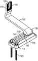
- FIGS. 11-13 shows perspective, side, and top views of an exemplary embodiment of a solar panel support structure 100 .
- the structure 100 includes a base 110 .
- the base or base plate 110 is generally planar but can be other shapes so long as it can fit beneath a typical roof tile 300 .
- the base plate 110 typically includes holes 120 on one side for receiving screws 125 for securing the base plate 110 to a roof.
- the other side of the base plate 110 also includes a guide that can be in the form of a slot guide 150 that is formed by a pair of rails 140 that are parallel to each other on opposite sides of the slot guide 150 .
- the slot guide 150 is generally open on both ends so that it can receive the locking mechanism 196 discussed below.
- the structure 100 also includes an elongated member that is typically a bracket 130 .
- the bracket 130 is typically curved in the shape of an “L” or an “S” and has a sufficient length so that it can conform to the shape of a typical roof tile.
- On one end of the bracket 130 is a generally U-shaped aperture 170 that includes opening 190 .
- the shape of the aperture 170 is not limited to one that has an opening 190 , but can also utilize a closed shape as well like the one shown in FIG. 1 .
- the aperture 170 generally is perpendicular to the base plate 110 so that when it subsequently receives a solar panel rail guide ( 350 in FIG. 4 ), the rail guide 350 will also be substantially perpendicular to the plane of the roof.
- FIG. 12A illustrates a close up of the aperture 170 .
- the surface of the U-shaped aperture 170 includes a plurality of grooves 180 that provide friction to prevent the rail guide 350 from slipping up or down the aperture 170 .
- Aperture 170 also includes a recessed path 182 that terminates at a lip 183 .
- FIG. 12B shows how once a fastener such as nut and bolt 187 is dropped into the opening 190 , the path 182 allows the nut and bolt 187 to move along the path 182 , but the lip 183 prevents the edge of the bolt 186 from slipping out of the opening 190 .
- the recessed path 182 on both sides of the bracket 130 allows the fasteners 187 and rail guide 350 to be installed on either side of the bracket 130 .
- the end opposite the aperture 170 on the bracket 130 includes a locking mechanism 196 that is inserted in either end of the slot guide 150 .
- the locking mechanism 196 in this exemplary embodiment comprises a pair of tabs 195 that may be spring-loaded or resilient tabs that, when actuated—in this case by squeezing together—the tabs 195 are raised above the upper surface of the rails 140 so that the bracket 130 can freely move laterally back and forth along the slot guide 150 while in an open position to a desired location.
- the open position in this embodiment typically means when at least one of the tabs 195 is being actuated.
- a single resilient tab 195 could be used, but a pair of resilient tabs 195 provides greater leverage when actuating the locking mechanism 196 .
- the tabs 195 When the tabs 195 are released to their normal default position, the tabs 195 are lowered on to the rails 140 and create substantial friction so that the locking mechanism 196 will lock and place the bracket 130 , which is typically referred to as a closed position along the guide 150 .
- FIGS. 14-16 provide a transparent view of the guide during the progression of moving the bracket 130 from left to right in the slot guide 150 .
- FIG. 14 shows the grips 195 squeezed toward the middle, which raises the tabs 195 above the rails 140 .
- FIG. 15 shows the bracket 130 move toward the right while the tabs 195 are squeezed together, and
- FIG. 16 shows the tabs 195 released to their default position so that the tabs 195 are lowered back on to the rails 140 thereby securing the bracket 130 in a locked position.
- FIG. 17 shows an alternate exemplary embodiment of the solar panel structure 100 .
- the base plate 110 can be positioned in various locations with elongated holes 122 and secured with the screws 125 .
- the slot guide 150 is also bounded by wall 142 on one end of the rails 140 .
- the wall 142 prevents the bracket 130 from escaping one end of the guide 150 .
- FIGS. 18-19 show top and perspective views respectively of the embodiment in FIG. 17 with a flashing cover 112 that envelops the base plate 110 to provide further protection from the elements.
- FIG. 20 illustrates a cross-section along the dashed line 20 in FIG. 19 .
- This illustration shows greater details of how the locking mechanism 196 interacts with the slot guide 150 and the rails 140 .
- the rails 140 include opposing downward flanges 141 whereby the contour of the slot guide 150 is filled by the locking mechanism 196 .
- Bottom tag 193 keeps the bracket 130 from escaping the base plate 110 once the installer has assembled them together.
- the tabs 195 are joined by a bottom side 197 , which includes the tag 193 as shown in detail in the bottom perspective view of FIG. 21 and the perspective view of FIG. 22 .
- FIGS. 23-27 show another exemplary embodiment of the solar panel support structure 100 .
- the bracket 130 and the base plate 110 are formed as one piece that utilizes the elongated holes 122 shown in the embodiment illustrated in FIG. 17 .
- the bracket 130 is typically secured in the middle of the base plate 110 .
- FIG. 28 shows a cross-sectional view along the 28 line in FIG. 27 .
- FIGS. 29-32 show another exemplary embodiment of the solar panel support structure 100 .
- FIG. 29 shows a perspective view of the structure 100 that includes a base plate 114 with a narrower profile of the plate 110 shown in previous embodiments.
- the holes 113 where screws 125 fit to secure the plate 114 to a roof are collinear with the rails 140 and the guide 150 for structural performance.
- This allows the base plate 114 to be secured to the roof from either side i.e. it is reversible.
- the reversibility allows greater flexibility to position the base plate 114 beneath the tiles during installation as will be shown below.
- the guide 150 is also closed on one end to limit the lateral movement of the bracket 130 and the locking mechanism 196 when the tabs 195 are in the unlocked position.
- FIG. 30 shows a top view and FIG. 32 shows a front view of the support structure 100 .
- FIG. 31 shows a bottom view of the structure 100 with a crease 500 around the perimeter to prevent slipping when the base plate 114 is secured to the roof.
- FIG. 33 shows the embodiment in FIGS. 29-32 with a reversible partial flashing 111 that encloses a portion of the base plate 114 , but leaves the bracket free to move laterally within the entire slot guide 150 , minimizes the flashing size, and covers the roof penetration points.
- FIGS. 35 and 36 show top and perspective views of the embodiment shown in FIGS. 29-32 with a full-sized version of flashing 111 . These figures also show the nut and bolt combination 191 that is used to secure a solar panel rail guide 350 to the bracket 130 .
- FIGS. 37-39 disclose an alternate exemplary embodiment of the spring lock mechanism 196 and how it is locked in place in the alternate embodiment disclosed in FIGS. 29-32 .
- FIG. 37 shows the bracket 130 and the resilient tabs 195 slide over a notch 199 on the base plate 114 when the spring lock 196 is fully unlocked by actuating (squeezing) the tabs 195 , which places it in an open position.
- This notch 199 serves to hold the bracket 130 to the base once the installer has assembled them together and eliminates accidental removal while the installer is adjusting the placement of the bracket 130 .
- FIG. 38 shows the tabs 195 in the locked position after being released, which locks the bracket to the base in a closed position while the installer is adjusting the position of the rail guide ( 350 ).
- FIG. 39 shows an alternate exemplary embodiment of the tabs 195 as separate elements. These tabs 195 are inserted and slide through thin slot 192 where notches 198 lock their placement in the bracket.
- the base plate 110 comprises an angled guide 150 with rails 140 .
- the bracket 130 is adjustable on the end that is inserted into the angled guide 150 by finding a desired lateral location along the angled guide 150 and then locating the desired vertical location of the end of the bracket 130 along ridges 400 , which are on the rails 140 .
- a nut 166 and bolt 165 combination 165 can then be used to tighten the bracket 130 to the angled guide 150 .
- FIGS. 1-7 A method of assembling a prior art structure 100 is shown in FIGS. 1-7 .
- the assembly method can apply to any of the structure embodiments described and illustrated the previous paragraphs.
- FIG. 1 shows that the first step is to remove any tiles 300 in the area where the structure 100 is to be installed.
- the tiles 300 shown are S-shaped concrete tiles, but other shapes such as flat tiles can be used as well.
- the roof 330 is revealed.
- the base plate 110 of the structure 100 with the bracket 130 secured by inserting bolt 121 through an end of the bracket 130 to the base plate 110 is placed flat on the roof 330 .
- this step is replaced by coupling the end of the bracket 130 through the guide 150 by actuating the locking mechanism 196 until the bracket 130 is positioned in a desired location.
- the base plate 110 is positioned on a rafter and in a location where the length of the bracket 130 extends past the edge of overlapping tiles 300 .
- FIG. 2 shows the next step, which is to secure the base plate 110 to the roof 330 .
- the figure shows this being accomplished by using a standard drill to insert the screws 125 through the holes 120 of the base plate 110 .
- FIG. 3 includes a step of covering the base plate 110 with a flashing 112 .
- the flashing 112 is optional and typically covers the entire base plate 110 but can also be a partial flashing 111 as shown in FIG. 33 .
- FIG. 4 is a perspective view the roof showing the rail guide 350 with a solar panel array 340 .
- the rail guide 350 will be connected to the bracket 130 and secured with a nut and bolt through the rail guide 350 and the aperture 170 .
- the grooves 180 will prevent the rail guide 350 from slipping downward.
- FIG. 6 shows the next step, which is to place the tiles 300 back in place.
- the vertical portion 175 of the bracket 130 is exposed revealing the aperture 170 and the grooves 180 .
- the rail guide 350 will be secured to the bracket 130 .
- FIG. 7 shows a close-up of the vertical portion 175 of the bracket 130 showing the grooves 180 and the aperture 170 .
Landscapes
- Engineering & Computer Science (AREA)
- Architecture (AREA)
- Structural Engineering (AREA)
- Civil Engineering (AREA)
- Chemical & Material Sciences (AREA)
- Thermal Sciences (AREA)
- Physics & Mathematics (AREA)
- Combustion & Propulsion (AREA)
- Mechanical Engineering (AREA)
- General Engineering & Computer Science (AREA)
- Sustainable Energy (AREA)
- Sustainable Development (AREA)
- Life Sciences & Earth Sciences (AREA)
- Roof Covering Using Slabs Or Stiff Sheets (AREA)
Abstract
Description
Claims (24)
Priority Applications (1)
| Application Number | Priority Date | Filing Date | Title |
|---|---|---|---|
| US15/550,016 US10663195B2 (en) | 2015-07-29 | 2016-07-29 | Tile roof mount |
Applications Claiming Priority (4)
| Application Number | Priority Date | Filing Date | Title |
|---|---|---|---|
| US201562198651P | 2015-07-29 | 2015-07-29 | |
| US201562251530P | 2015-11-05 | 2015-11-05 | |
| PCT/US2016/044754 WO2017019971A1 (en) | 2015-07-29 | 2016-07-29 | Tile roof mount |
| US15/550,016 US10663195B2 (en) | 2015-07-29 | 2016-07-29 | Tile roof mount |
Related Parent Applications (1)
| Application Number | Title | Priority Date | Filing Date |
|---|---|---|---|
| PCT/US2016/044754 A-371-Of-International WO2017019971A1 (en) | 2015-07-29 | 2016-07-29 | Tile roof mount |
Related Child Applications (1)
| Application Number | Title | Priority Date | Filing Date |
|---|---|---|---|
| US16/842,687 Continuation US11009262B2 (en) | 2015-07-29 | 2020-04-07 | Tile roof mount |
Publications (2)
| Publication Number | Publication Date |
|---|---|
| US20180238589A1 US20180238589A1 (en) | 2018-08-23 |
| US10663195B2 true US10663195B2 (en) | 2020-05-26 |
Family
ID=57885040
Family Applications (2)
| Application Number | Title | Priority Date | Filing Date |
|---|---|---|---|
| US15/550,016 Active 2036-09-19 US10663195B2 (en) | 2015-07-29 | 2016-07-29 | Tile roof mount |
| US16/842,687 Active US11009262B2 (en) | 2015-07-29 | 2020-04-07 | Tile roof mount |
Family Applications After (1)
| Application Number | Title | Priority Date | Filing Date |
|---|---|---|---|
| US16/842,687 Active US11009262B2 (en) | 2015-07-29 | 2020-04-07 | Tile roof mount |
Country Status (2)
| Country | Link |
|---|---|
| US (2) | US10663195B2 (en) |
| WO (1) | WO2017019971A1 (en) |
Cited By (13)
| Publication number | Priority date | Publication date | Assignee | Title |
|---|---|---|---|---|
| US11009262B2 (en) * | 2015-07-29 | 2021-05-18 | Ironridge, Inc. | Tile roof mount |
| EP4075077A1 (en) * | 2021-04-15 | 2022-10-19 | Renusol Europe GmbH | Solar module mounting system |
| US20220352848A1 (en) * | 2021-04-28 | 2022-11-03 | Unirac Inc. | Sealable mounting system with a slidable component mount |
| US20230258295A1 (en) * | 2021-05-21 | 2023-08-17 | Unirac Inc. | Attachment bracket apparatus |
| US11962137B2 (en) | 2020-04-21 | 2024-04-16 | Unirac Inc. | Electric junction box mount apparatus |
| IT202200022935A1 (en) * | 2022-11-07 | 2024-05-07 | Ev Services S R L | MOUNTING SYSTEM FOR PHOTOVOLTAIC MODULES, SOLAR THERMAL PANELS OR OTHER ROOF SUPERSTRUCTURES |
| EP4407864A1 (en) * | 2023-01-24 | 2024-07-31 | Sunmodo Corporation | Bracket and devices for mounting solar panel to roofs |
| US20250070708A1 (en) * | 2023-08-25 | 2025-02-27 | Unirac, Inc. | Mounting devices |
| USD1095404S1 (en) * | 2024-01-18 | 2025-09-30 | Jing-Xin Solar Ltd. | Fixed bracket for solar panel |
| USD1095402S1 (en) * | 2024-01-18 | 2025-09-30 | Jing-Xin Solar Ltd. | Fixed bracket for solar panel |
| US12428844B2 (en) | 2021-05-21 | 2025-09-30 | Unirac, Inc. | Attachment bracket apparatus |
| US12546348B2 (en) | 2021-12-13 | 2026-02-10 | Tamarack Solar Products, Inc. | Solar panel mounting configuration |
| US12556127B1 (en) * | 2017-09-01 | 2026-02-17 | Tamarack Solar Products, Inc. | Solar panel mounting configuration |
Families Citing this family (27)
| Publication number | Priority date | Publication date | Assignee | Title |
|---|---|---|---|---|
| US9611652B2 (en) | 2011-02-25 | 2017-04-04 | Dustin M. M. Haddock | Mounting device for building surfaces having elongated mounting slot |
| WO2013101597A1 (en) | 2011-12-29 | 2013-07-04 | Haddock Dustin M M | Mounting device for nail strip panels |
| US10443896B2 (en) | 2016-07-29 | 2019-10-15 | Rmh Tech Llc | Trapezoidal rib mounting bracket with flexible legs |
| US10601362B2 (en) | 2016-09-09 | 2020-03-24 | Pegasus Solar Inc. | Tile replacement solar mounting system |
| US10630228B2 (en) | 2016-10-05 | 2020-04-21 | Samuel Marcus-Flack Truthseeker | Systems and methods for mounting roof-mounted photovoltaic arrays including flashing and tape |
| US20180115274A1 (en) * | 2016-10-26 | 2018-04-26 | Pegasus Solar Inc. | Tile replacement solar mounting system |
| WO2018081722A1 (en) | 2016-10-31 | 2018-05-03 | Haddock Dustin M M | Metal panel electrical bonding clip |
| NZ764108A (en) | 2017-10-09 | 2022-08-26 | Rmh Tech Llc | Rail assembly attachable to a building surface |
| CN110270681A (en) * | 2018-03-15 | 2019-09-24 | 宝钢特钢有限公司 | Stopper anti-drop device on a kind of tundish |
| WO2019183388A1 (en) | 2018-03-21 | 2019-09-26 | Rmh Tech Llc | Pv module mounting assembly with clamp/standoff arrangement |
| WO2020124011A1 (en) | 2018-12-14 | 2020-06-18 | Rmh Tech Llc | Mounting device for nail strip panels |
| CN110912499A (en) * | 2019-12-19 | 2020-03-24 | 朱国浩 | A hook for installing solar photovoltaic modules |
| AU2021239839B2 (en) | 2020-03-16 | 2024-12-19 | Rmh Tech Llc | Mounting device for a metal roof |
| US11041310B1 (en) | 2020-03-17 | 2021-06-22 | Rmh Tech Llc | Mounting device for controlling uplift of a metal roof |
| BR112023000401A2 (en) | 2020-07-09 | 2023-01-31 | Rmh Tech Llc | SYSTEM, DEVICE AND ASSEMBLY METHOD |
| MX2023009078A (en) * | 2021-02-03 | 2023-08-08 | Unirac Inc | Roof interface with sealant injection ports. |
| US12483185B2 (en) | 2021-09-09 | 2025-11-25 | Rmh Tech Llc | Torque actuated rail assembly |
| USD990289S1 (en) * | 2021-12-14 | 2023-06-27 | Taylor M. Hong | Bracket |
| WO2024011154A1 (en) | 2022-07-06 | 2024-01-11 | Rmh Tech Llc | Pv module mounting assembly with clamp / standoff arrangement |
| USD1075493S1 (en) | 2022-07-06 | 2025-05-20 | Rmh Tech Llc | Clamp for a photovoltaic module mounting assembly |
| US12463580B2 (en) * | 2022-07-15 | 2025-11-04 | Sunrun Inc. | Mount and clamp assemblies |
| USD1113406S1 (en) | 2023-04-14 | 2026-02-17 | Rmh Tech Llc | Mounting device |
| CN121358993A (en) | 2023-04-14 | 2026-01-16 | Rmh技术有限责任公司 | Mounting device for metal panels |
| EP4492676A1 (en) * | 2023-06-09 | 2025-01-15 | Esdec B.V. | Device for mounting at least one solar panel to a roof |
| NL2035058B1 (en) * | 2023-06-09 | 2024-12-19 | Esdec B V | Device for mounting at least one solar panel to a roof |
| USD1109686S1 (en) | 2023-08-10 | 2026-01-20 | Rmh Tech Llc | Mount for a component of a photovoltaic assembly |
| USD1091448S1 (en) | 2023-10-10 | 2025-09-02 | Bluescope Buildings North America, Inc. | Solar panel frame bracket |
Citations (31)
| Publication number | Priority date | Publication date | Assignee | Title |
|---|---|---|---|---|
| US6146071A (en) | 1999-04-14 | 2000-11-14 | Illinois Tool Works, Inc. | Caged nut assembly |
| US20040216399A1 (en) | 2003-01-30 | 2004-11-04 | Kyocera Corporation | Fixing apparatus |
| US20060156648A1 (en) | 2005-01-04 | 2006-07-20 | Thompson Daniel S | Apparatus for mounting a solar panel or other article to a roof or other structure |
| EP1764454A2 (en) | 2005-09-15 | 2007-03-21 | Kieselbach Maschinenbauteile GmbH | Hook for mounting modules of a solar installation to a roof |
| US7246547B2 (en) | 2002-11-11 | 2007-07-24 | J. Van Walraven Holding B.V. | Assembly of a nut body in a profiled-section element |
| DE202009003745U1 (en) | 2009-03-19 | 2009-07-16 | Haslinger, Rüdiger, Dipl.-Betriebsw. (FH) | Multi-part roof hook system |
| US20110248131A1 (en) | 2008-11-28 | 2011-10-13 | Haticon Gmbh | Two-part roof hook |
| EP2474796A1 (en) | 2010-12-10 | 2012-07-11 | Würth Solar GmbH & Co. KG | Ceiling hook, in particular for support structures |
| US20120275844A1 (en) | 2010-02-02 | 2012-11-01 | Yanegijutsukenkyujo Co., Ltd. | Securing member |
| EP2527762A1 (en) | 2011-05-26 | 2012-11-28 | Milboro Aktiengesellschaft | Attachment device |
| US20130161462A1 (en) * | 2011-12-23 | 2013-06-27 | Dustin M.M. Haddock | Mounting device using a lifting clamping action for installation on panel assembly |
| US20130206941A1 (en) | 2010-09-22 | 2013-08-15 | Kieselbach Solar Gmbh | Roof hook for installing solar system modules on roofs |
| US20140003861A1 (en) | 2012-07-02 | 2014-01-02 | A. Raymond Et Cie | Photovoltaic frame fastener |
| US20140026946A1 (en) | 2011-12-13 | 2014-01-30 | Zep Solar, Inc. | Discrete Attachment Point Apparatus and System for Photovoltaic Arrays |
| US8806815B1 (en) | 2013-10-15 | 2014-08-19 | Sunmodo Corporation | Adjustable solar panel tile roof mounting device |
| US8839575B1 (en) | 2013-10-15 | 2014-09-23 | Sunmodo Corporation | Adjustable solar panel tile roof mounting device |
| US20150060619A1 (en) * | 2012-03-19 | 2015-03-05 | K2 Systems Gmbh | Solar module bracket |
| US20160006390A1 (en) * | 2014-07-07 | 2016-01-07 | Spice Solar, Inc. | Solar Panel Mechanical Connector And Frame |
| US20160054030A1 (en) * | 2013-03-28 | 2016-02-25 | Werner Ilzhöfer | Fastening element for fastening solar modules to an inclined roof surface |
| US20160087576A1 (en) * | 2014-09-23 | 2016-03-24 | Solarcity Corporation | Photovoltaic mounting system for tiled roofs |
| US20160105143A1 (en) * | 2014-10-13 | 2016-04-14 | Solarcity Corporation | Integrated hook and flashing for photovoltaic module installation on tile roofs |
| US20160134230A1 (en) * | 2014-11-06 | 2016-05-12 | Ironridge, Inc. | Roof Attachment Flashing Assembly |
| US20160308486A1 (en) * | 2015-04-17 | 2016-10-20 | Moti Atia | Solar panel mounting apparatus with enhanced strength |
| US20170063287A1 (en) * | 2015-08-27 | 2017-03-02 | Solarcity Corporation | Support system for photovoltaic mounting rail having cylindrical base that rotates into a locked position |
| US20180062571A1 (en) * | 2015-08-31 | 2018-03-01 | Ironridge, Inc. | Apparatus for Securing a Solar Panel Rail Guide to a Support Bracket |
| US20180106289A1 (en) * | 2015-07-29 | 2018-04-19 | Ironridge, Inc. | Bracket Mount for Securing Solar Panel Rail Guides on Shingle Roofs |
| US9954479B1 (en) * | 2016-08-02 | 2018-04-24 | Moti Atia | Mounting apparatus to secure solar panel rails to flat tile roofs |
| US20180167020A1 (en) * | 2016-12-14 | 2018-06-14 | Tecsi Solar, Inc. | Systems and methods for mounting roof-mounted photovoltaic arrays including flashing and adhesive pads |
| US10277162B1 (en) * | 2016-08-16 | 2019-04-30 | Moti Atia | Mounting apparatus to secure a solar panel rail to stone-coated metal tile roofs |
| US20190131917A1 (en) * | 2017-10-30 | 2019-05-02 | Solar Slate Solutions | Solar panel mount with compression spacer systems and methods |
| US10320325B1 (en) * | 2016-08-02 | 2019-06-11 | Moti Atia | Mounting apparatus to secure solar panel rails to stone-coated metal tile roofs |
Family Cites Families (7)
| Publication number | Priority date | Publication date | Assignee | Title |
|---|---|---|---|---|
| WO2001011163A1 (en) * | 1999-08-11 | 2001-02-15 | Solar Strategies Development, Inc. | Mounting apparatus and photovoltaic mounting system for a solar panel and method of mounting a solar panel |
| US9611652B2 (en) * | 2011-02-25 | 2017-04-04 | Dustin M. M. Haddock | Mounting device for building surfaces having elongated mounting slot |
| US9397607B2 (en) * | 2011-11-09 | 2016-07-19 | Solarcity Corporation | Self-locking photovoltaic module mounting system |
| US8752338B2 (en) * | 2012-05-04 | 2014-06-17 | D Three Enterprises, Llc | Adjustable roof mounting system |
| JP5830168B2 (en) * | 2012-07-10 | 2015-12-09 | 日晴金属株式会社 | Solar panel mount |
| US10663195B2 (en) * | 2015-07-29 | 2020-05-26 | Ironridge, Inc. | Tile roof mount |
| US10236821B1 (en) * | 2016-08-02 | 2019-03-19 | Moti Atia | Mounting apparatus to secure solar panel rails to S-tile roofs |
-
2016
- 2016-07-29 US US15/550,016 patent/US10663195B2/en active Active
- 2016-07-29 WO PCT/US2016/044754 patent/WO2017019971A1/en not_active Ceased
-
2020
- 2020-04-07 US US16/842,687 patent/US11009262B2/en active Active
Patent Citations (35)
| Publication number | Priority date | Publication date | Assignee | Title |
|---|---|---|---|---|
| US6146071A (en) | 1999-04-14 | 2000-11-14 | Illinois Tool Works, Inc. | Caged nut assembly |
| US7246547B2 (en) | 2002-11-11 | 2007-07-24 | J. Van Walraven Holding B.V. | Assembly of a nut body in a profiled-section element |
| US20040216399A1 (en) | 2003-01-30 | 2004-11-04 | Kyocera Corporation | Fixing apparatus |
| US20060156648A1 (en) | 2005-01-04 | 2006-07-20 | Thompson Daniel S | Apparatus for mounting a solar panel or other article to a roof or other structure |
| EP1764454A2 (en) | 2005-09-15 | 2007-03-21 | Kieselbach Maschinenbauteile GmbH | Hook for mounting modules of a solar installation to a roof |
| US20110248131A1 (en) | 2008-11-28 | 2011-10-13 | Haticon Gmbh | Two-part roof hook |
| US8844887B2 (en) * | 2008-11-28 | 2014-09-30 | Haticon Gmbh | Two-part roof hook |
| DE202009003745U1 (en) | 2009-03-19 | 2009-07-16 | Haslinger, Rüdiger, Dipl.-Betriebsw. (FH) | Multi-part roof hook system |
| US20120275844A1 (en) | 2010-02-02 | 2012-11-01 | Yanegijutsukenkyujo Co., Ltd. | Securing member |
| US8647009B2 (en) * | 2010-02-02 | 2014-02-11 | Yanegijutsukenkyujo Co., Ltd. | Securing member |
| US20130206941A1 (en) | 2010-09-22 | 2013-08-15 | Kieselbach Solar Gmbh | Roof hook for installing solar system modules on roofs |
| US9151519B2 (en) * | 2010-09-22 | 2015-10-06 | Kieselbach Solar Gmbh | Mounting system for installing solar system modules on roofs |
| EP2474796A1 (en) | 2010-12-10 | 2012-07-11 | Würth Solar GmbH & Co. KG | Ceiling hook, in particular for support structures |
| EP2527762A1 (en) | 2011-05-26 | 2012-11-28 | Milboro Aktiengesellschaft | Attachment device |
| US20140026946A1 (en) | 2011-12-13 | 2014-01-30 | Zep Solar, Inc. | Discrete Attachment Point Apparatus and System for Photovoltaic Arrays |
| US20130161462A1 (en) * | 2011-12-23 | 2013-06-27 | Dustin M.M. Haddock | Mounting device using a lifting clamping action for installation on panel assembly |
| US20150060619A1 (en) * | 2012-03-19 | 2015-03-05 | K2 Systems Gmbh | Solar module bracket |
| US20140003861A1 (en) | 2012-07-02 | 2014-01-02 | A. Raymond Et Cie | Photovoltaic frame fastener |
| US20160054030A1 (en) * | 2013-03-28 | 2016-02-25 | Werner Ilzhöfer | Fastening element for fastening solar modules to an inclined roof surface |
| US8839575B1 (en) | 2013-10-15 | 2014-09-23 | Sunmodo Corporation | Adjustable solar panel tile roof mounting device |
| US8806815B1 (en) | 2013-10-15 | 2014-08-19 | Sunmodo Corporation | Adjustable solar panel tile roof mounting device |
| US20160006390A1 (en) * | 2014-07-07 | 2016-01-07 | Spice Solar, Inc. | Solar Panel Mechanical Connector And Frame |
| US20160087576A1 (en) * | 2014-09-23 | 2016-03-24 | Solarcity Corporation | Photovoltaic mounting system for tiled roofs |
| US20160105143A1 (en) * | 2014-10-13 | 2016-04-14 | Solarcity Corporation | Integrated hook and flashing for photovoltaic module installation on tile roofs |
| US20160134230A1 (en) * | 2014-11-06 | 2016-05-12 | Ironridge, Inc. | Roof Attachment Flashing Assembly |
| US20160308486A1 (en) * | 2015-04-17 | 2016-10-20 | Moti Atia | Solar panel mounting apparatus with enhanced strength |
| US20180106289A1 (en) * | 2015-07-29 | 2018-04-19 | Ironridge, Inc. | Bracket Mount for Securing Solar Panel Rail Guides on Shingle Roofs |
| US20190345971A1 (en) * | 2015-07-29 | 2019-11-14 | Ironridge, Inc. | Bracket Mount for Securing Solar Panel Rail Guides on a Roof |
| US20170063287A1 (en) * | 2015-08-27 | 2017-03-02 | Solarcity Corporation | Support system for photovoltaic mounting rail having cylindrical base that rotates into a locked position |
| US20180062571A1 (en) * | 2015-08-31 | 2018-03-01 | Ironridge, Inc. | Apparatus for Securing a Solar Panel Rail Guide to a Support Bracket |
| US9954479B1 (en) * | 2016-08-02 | 2018-04-24 | Moti Atia | Mounting apparatus to secure solar panel rails to flat tile roofs |
| US10320325B1 (en) * | 2016-08-02 | 2019-06-11 | Moti Atia | Mounting apparatus to secure solar panel rails to stone-coated metal tile roofs |
| US10277162B1 (en) * | 2016-08-16 | 2019-04-30 | Moti Atia | Mounting apparatus to secure a solar panel rail to stone-coated metal tile roofs |
| US20180167020A1 (en) * | 2016-12-14 | 2018-06-14 | Tecsi Solar, Inc. | Systems and methods for mounting roof-mounted photovoltaic arrays including flashing and adhesive pads |
| US20190131917A1 (en) * | 2017-10-30 | 2019-05-02 | Solar Slate Solutions | Solar panel mount with compression spacer systems and methods |
Cited By (18)
| Publication number | Priority date | Publication date | Assignee | Title |
|---|---|---|---|---|
| US11009262B2 (en) * | 2015-07-29 | 2021-05-18 | Ironridge, Inc. | Tile roof mount |
| US12556127B1 (en) * | 2017-09-01 | 2026-02-17 | Tamarack Solar Products, Inc. | Solar panel mounting configuration |
| US12494627B2 (en) | 2020-04-21 | 2025-12-09 | Unirac, Inc. | Electric junction box mount apparatus |
| US11962137B2 (en) | 2020-04-21 | 2024-04-16 | Unirac Inc. | Electric junction box mount apparatus |
| EP4075077A1 (en) * | 2021-04-15 | 2022-10-19 | Renusol Europe GmbH | Solar module mounting system |
| US12068715B2 (en) * | 2021-04-28 | 2024-08-20 | Unirac Inc. | Sealable mounting system with a slidable component mount |
| US20220352848A1 (en) * | 2021-04-28 | 2022-11-03 | Unirac Inc. | Sealable mounting system with a slidable component mount |
| US12428844B2 (en) | 2021-05-21 | 2025-09-30 | Unirac, Inc. | Attachment bracket apparatus |
| US12474014B2 (en) * | 2021-05-21 | 2025-11-18 | Unirac, Inc. | Attachment bracket apparatus |
| US20230258295A1 (en) * | 2021-05-21 | 2023-08-17 | Unirac Inc. | Attachment bracket apparatus |
| US12546348B2 (en) | 2021-12-13 | 2026-02-10 | Tamarack Solar Products, Inc. | Solar panel mounting configuration |
| EP4365508A1 (en) * | 2022-11-07 | 2024-05-08 | EV Services S.r.l. | Clamping system for photovoltaic modules, solar thermal panels or other roof superstructures |
| IT202200022935A1 (en) * | 2022-11-07 | 2024-05-07 | Ev Services S R L | MOUNTING SYSTEM FOR PHOTOVOLTAIC MODULES, SOLAR THERMAL PANELS OR OTHER ROOF SUPERSTRUCTURES |
| EP4407864A1 (en) * | 2023-01-24 | 2024-07-31 | Sunmodo Corporation | Bracket and devices for mounting solar panel to roofs |
| US20250070708A1 (en) * | 2023-08-25 | 2025-02-27 | Unirac, Inc. | Mounting devices |
| US12470166B2 (en) * | 2023-08-25 | 2025-11-11 | Unirac, Inc. | Mounting devices |
| USD1095404S1 (en) * | 2024-01-18 | 2025-09-30 | Jing-Xin Solar Ltd. | Fixed bracket for solar panel |
| USD1095402S1 (en) * | 2024-01-18 | 2025-09-30 | Jing-Xin Solar Ltd. | Fixed bracket for solar panel |
Also Published As
| Publication number | Publication date |
|---|---|
| US20200232681A1 (en) | 2020-07-23 |
| US11009262B2 (en) | 2021-05-18 |
| WO2017019971A1 (en) | 2017-02-02 |
| US20180238589A1 (en) | 2018-08-23 |
Similar Documents
| Publication | Publication Date | Title |
|---|---|---|
| US11009262B2 (en) | Tile roof mount | |
| US20250202414A1 (en) | Solar Module Mounting System | |
| US10365017B2 (en) | Self-adjusting end clamp | |
| US20220278516A1 (en) | Wire Management Structure for a Rail-Less Solar Panel Assembly | |
| US9455662B2 (en) | Assembly for locking and grounding solar panel modules to mounting components | |
| US10027276B2 (en) | Photovoltaic mounting system | |
| US10027273B2 (en) | Plunger and puck mounting system for photovoltaic panels | |
| US9985577B2 (en) | Assembly for locking and grounding solar panel modules to mounting components | |
| US20160268959A1 (en) | Rail-Less Solar Panel Assembly and Installation Method | |
| US10187004B2 (en) | Slide-on spring clip for installing solar panels and method of use | |
| CN104040879A (en) | System and method for establishing a self-aligning mounting system for mounting photovoltaic modules | |
| US20130299655A1 (en) | Anchor system for anchring a mounting system for photovoltaic modules | |
| US20160079909A1 (en) | Photovoltaic panel mounting system | |
| US20130294814A1 (en) | Friction locking retainer for photovoltaic module mounting system | |
| US9793852B2 (en) | Clamp and bowl mounting system for photovoltaic modules | |
| US10135386B2 (en) | Sensing, interlocking solar module system and installation method | |
| JPWO2018061645A1 (en) | Solar power generator | |
| US20130291472A1 (en) | Removable water cap for photovoltaic module mounting system | |
| US20150357965A1 (en) | Retaining device for solar cell module | |
| JP5891109B2 (en) | Solar cell module fixing structure and solar cell module fixing method | |
| US7386961B2 (en) | Bracket, method of making, and method of mounting rooftop elements on rooftop structure | |
| JPWO2018061696A1 (en) | Solar power generator | |
| JP5534454B2 (en) | Panel holder and exterior structure using the same | |
| JP6118099B2 (en) | Panel fixing device and installation method | |
| JPWO2018061649A1 (en) | Solar power generator |
Legal Events
| Date | Code | Title | Description |
|---|---|---|---|
| FEPP | Fee payment procedure |
Free format text: ENTITY STATUS SET TO SMALL (ORIGINAL EVENT CODE: SMAL); ENTITY STATUS OF PATENT OWNER: SMALL ENTITY |
|
| STPP | Information on status: patent application and granting procedure in general |
Free format text: DOCKETED NEW CASE - READY FOR EXAMINATION |
|
| STPP | Information on status: patent application and granting procedure in general |
Free format text: NON FINAL ACTION MAILED |
|
| STPP | Information on status: patent application and granting procedure in general |
Free format text: RESPONSE TO NON-FINAL OFFICE ACTION ENTERED AND FORWARDED TO EXAMINER |
|
| STPP | Information on status: patent application and granting procedure in general |
Free format text: NON FINAL ACTION MAILED |
|
| AS | Assignment |
Owner name: IRONRIDGE, INC., ARIZONA Free format text: ASSIGNMENT OF ASSIGNORS INTEREST;ASSIGNORS:MEINE, SHAWN, MR;ASH, JON, MR;NARAIN, ANUMEHA, MS;AND OTHERS;REEL/FRAME:050196/0842 Effective date: 20160726 |
|
| STPP | Information on status: patent application and granting procedure in general |
Free format text: PUBLICATIONS -- ISSUE FEE PAYMENT RECEIVED |
|
| STPP | Information on status: patent application and granting procedure in general |
Free format text: PUBLICATIONS -- ISSUE FEE PAYMENT VERIFIED |
|
| FEPP | Fee payment procedure |
Free format text: PETITION RELATED TO MAINTENANCE FEES GRANTED (ORIGINAL EVENT CODE: PTGR); ENTITY STATUS OF PATENT OWNER: SMALL ENTITY |
|
| STCF | Information on status: patent grant |
Free format text: PATENTED CASE |
|
| AS | Assignment |
Owner name: WILMINGTON TRUST, NATIONAL ASSOCIATION, DELAWARE Free format text: SECURITY INTEREST;ASSIGNORS:ECOFASTEN SOLAR, LLC;IRONRIDGE, INC.;PANELCLAW, INC.;AND OTHERS;REEL/FRAME:057365/0001 Effective date: 20210830 |
|
| FEPP | Fee payment procedure |
Free format text: ENTITY STATUS SET TO UNDISCOUNTED (ORIGINAL EVENT CODE: BIG.); ENTITY STATUS OF PATENT OWNER: LARGE ENTITY |
|
| FEPP | Fee payment procedure |
Free format text: MAINTENANCE FEE REMINDER MAILED (ORIGINAL EVENT CODE: REM.); ENTITY STATUS OF PATENT OWNER: LARGE ENTITY |
|
| FEPP | Fee payment procedure |
Free format text: SURCHARGE FOR LATE PAYMENT, LARGE ENTITY (ORIGINAL EVENT CODE: M1554); ENTITY STATUS OF PATENT OWNER: LARGE ENTITY |
|
| MAFP | Maintenance fee payment |
Free format text: PAYMENT OF MAINTENANCE FEE, 4TH YEAR, LARGE ENTITY (ORIGINAL EVENT CODE: M1551); ENTITY STATUS OF PATENT OWNER: LARGE ENTITY Year of fee payment: 4 |