US10663055B2 - Differential gear device - Google Patents
Differential gear device Download PDFInfo
- Publication number
- US10663055B2 US10663055B2 US16/211,340 US201816211340A US10663055B2 US 10663055 B2 US10663055 B2 US 10663055B2 US 201816211340 A US201816211340 A US 201816211340A US 10663055 B2 US10663055 B2 US 10663055B2
- Authority
- US
- United States
- Prior art keywords
- differential
- differential casing
- annular seating
- axis
- side gears
- Prior art date
- Legal status (The legal status is an assumption and is not a legal conclusion. Google has not performed a legal analysis and makes no representation as to the accuracy of the status listed.)
- Expired - Fee Related, expires
Links
- 230000033001 locomotion Effects 0.000 claims abstract description 20
- 239000000314 lubricant Substances 0.000 claims description 140
- 238000005461 lubrication Methods 0.000 description 7
- 230000005540 biological transmission Effects 0.000 description 3
- 238000011144 upstream manufacturing Methods 0.000 description 3
- 238000005266 casting Methods 0.000 description 1
- 230000007423 decrease Effects 0.000 description 1
- 230000001050 lubricating effect Effects 0.000 description 1
- 230000007246 mechanism Effects 0.000 description 1
- 230000004048 modification Effects 0.000 description 1
- 238000012986 modification Methods 0.000 description 1
- 230000003449 preventive effect Effects 0.000 description 1
Images


Classifications
-
- F—MECHANICAL ENGINEERING; LIGHTING; HEATING; WEAPONS; BLASTING
- F16—ENGINEERING ELEMENTS AND UNITS; GENERAL MEASURES FOR PRODUCING AND MAINTAINING EFFECTIVE FUNCTIONING OF MACHINES OR INSTALLATIONS; THERMAL INSULATION IN GENERAL
- F16H—GEARING
- F16H48/00—Differential gearings
- F16H48/38—Constructional details
-
- F—MECHANICAL ENGINEERING; LIGHTING; HEATING; WEAPONS; BLASTING
- F16—ENGINEERING ELEMENTS AND UNITS; GENERAL MEASURES FOR PRODUCING AND MAINTAINING EFFECTIVE FUNCTIONING OF MACHINES OR INSTALLATIONS; THERMAL INSULATION IN GENERAL
- F16H—GEARING
- F16H57/00—General details of gearing
- F16H57/04—Features relating to lubrication or cooling or heating
- F16H57/042—Guidance of lubricant
- F16H57/0427—Guidance of lubricant on rotary parts, e.g. using baffles for collecting lubricant by centrifugal force
-
- F—MECHANICAL ENGINEERING; LIGHTING; HEATING; WEAPONS; BLASTING
- F16—ENGINEERING ELEMENTS AND UNITS; GENERAL MEASURES FOR PRODUCING AND MAINTAINING EFFECTIVE FUNCTIONING OF MACHINES OR INSTALLATIONS; THERMAL INSULATION IN GENERAL
- F16H—GEARING
- F16H48/00—Differential gearings
- F16H48/06—Differential gearings with gears having orbital motion
- F16H48/08—Differential gearings with gears having orbital motion comprising bevel gears
-
- F—MECHANICAL ENGINEERING; LIGHTING; HEATING; WEAPONS; BLASTING
- F16—ENGINEERING ELEMENTS AND UNITS; GENERAL MEASURES FOR PRODUCING AND MAINTAINING EFFECTIVE FUNCTIONING OF MACHINES OR INSTALLATIONS; THERMAL INSULATION IN GENERAL
- F16H—GEARING
- F16H48/00—Differential gearings
- F16H48/38—Constructional details
- F16H48/40—Constructional details characterised by features of the rotating cases
-
- F—MECHANICAL ENGINEERING; LIGHTING; HEATING; WEAPONS; BLASTING
- F16—ENGINEERING ELEMENTS AND UNITS; GENERAL MEASURES FOR PRODUCING AND MAINTAINING EFFECTIVE FUNCTIONING OF MACHINES OR INSTALLATIONS; THERMAL INSULATION IN GENERAL
- F16H—GEARING
- F16H57/00—General details of gearing
- F16H57/04—Features relating to lubrication or cooling or heating
- F16H57/042—Guidance of lubricant
- F16H57/043—Guidance of lubricant within rotary parts, e.g. axial channels or radial openings in shafts
-
- F—MECHANICAL ENGINEERING; LIGHTING; HEATING; WEAPONS; BLASTING
- F16—ENGINEERING ELEMENTS AND UNITS; GENERAL MEASURES FOR PRODUCING AND MAINTAINING EFFECTIVE FUNCTIONING OF MACHINES OR INSTALLATIONS; THERMAL INSULATION IN GENERAL
- F16H—GEARING
- F16H57/00—General details of gearing
- F16H57/04—Features relating to lubrication or cooling or heating
- F16H57/0457—Splash lubrication
-
- F—MECHANICAL ENGINEERING; LIGHTING; HEATING; WEAPONS; BLASTING
- F16—ENGINEERING ELEMENTS AND UNITS; GENERAL MEASURES FOR PRODUCING AND MAINTAINING EFFECTIVE FUNCTIONING OF MACHINES OR INSTALLATIONS; THERMAL INSULATION IN GENERAL
- F16H—GEARING
- F16H57/00—General details of gearing
- F16H57/04—Features relating to lubrication or cooling or heating
- F16H57/0467—Elements of gearings to be lubricated, cooled or heated
- F16H57/0469—Bearings or seals
- F16H57/0471—Bearing
-
- F—MECHANICAL ENGINEERING; LIGHTING; HEATING; WEAPONS; BLASTING
- F16—ENGINEERING ELEMENTS AND UNITS; GENERAL MEASURES FOR PRODUCING AND MAINTAINING EFFECTIVE FUNCTIONING OF MACHINES OR INSTALLATIONS; THERMAL INSULATION IN GENERAL
- F16H—GEARING
- F16H57/00—General details of gearing
- F16H57/04—Features relating to lubrication or cooling or heating
- F16H57/048—Type of gearings to be lubricated, cooled or heated
- F16H57/0482—Gearings with gears having orbital motion
- F16H57/0483—Axle or inter-axle differentials
-
- F—MECHANICAL ENGINEERING; LIGHTING; HEATING; WEAPONS; BLASTING
- F16—ENGINEERING ELEMENTS AND UNITS; GENERAL MEASURES FOR PRODUCING AND MAINTAINING EFFECTIVE FUNCTIONING OF MACHINES OR INSTALLATIONS; THERMAL INSULATION IN GENERAL
- F16H—GEARING
- F16H48/00—Differential gearings
- F16H48/38—Constructional details
- F16H2048/387—Shields or washers
Definitions
- the present invention relates to a differential gear device including a differential casing and a pair of side gears, and more particularly to lubrication between seating surfaces of the differential casing and the side gears.
- a differential gear device including: (a) a differential casing rotatable about an axis; and (b) a pair of side gears which are disposed within the differential casing such that the side gears are rotatable about the above-indicated axis, such that the side gears are opposed to each other, and such that a rotary motion of the differential casing about the above-indicated axis is transmitted to the side gears through pinion gears, so as to permit differential rotary motions of the side gears.
- the differential casing has a pair of bearing portions which extend from its respective inner surfaces toward back surfaces of the respective side gears and which have respective annular seating surfaces which are coaxial with the respective side gears and which receive axial loads from the side gears.
- JP-2017-116035A discloses an example of such a differential gear device.
- a lubricant oil in the differential casing is splashed up by the side gears, and a differential ring gear attached to the differential casing, to lubricate various parts of the differential gear device.
- annular seating surfaces of the differential casing which are provided for the respective side gears, have lubricant grooves formed so as to extend from their inner edges to their outer edges, while back surfaces of the side gears have lubricant scattering preventive portions at their outer edges, to hold the lubricant oil between the seating surfaces and the back surfaces of the side gears, for lubricating washers interposed therebetween, for instance.
- inner circumferential surfaces of bores which are formed through the differential casing and through which rotary shafts connected to the side gears extend have spiral grooves through which the lubricant oil outside the differential casing is introduced into the differential casing and directed in between the seating surfaces and the back surfaces of the side gears.
- the differential gear device constructed as described above has a problem of a low resistance to seizure due to shortage of an amount of the lubricant oil supplied in between the back surfaces of the side gears and the seating surfaces when the differential gear device is placed in a differential state in which one of the two side gears is held stationary and does not function to splash up the lubricant oil within the differential casing.
- This problem is serious particularly where a level of the lubricant oil within the differential casing is lowered to reduce a power loss due to the splashing of the lubricant oil.
- the problem is also serious where the lubricant oil has a low temperature, and has a high degree of viscosity and an accordingly low degree of fluidity at a low temperature of the lubricant oil.
- the present invention was made in view of the background art described above. It is therefore an object of the present invention to provide a differential gear device which permits sufficient lubrication between the back surfaces of the side gears and the seating surfaces of the differential casing, even in the differential state in which one of the two side gears is held stationary.
- a differential gear device comprising: a differential casing rotatable about an axis; and a pair of side gears which are disposed within the differential casing such that the side gears are rotatable about the above-indicated axis and axially opposed to each other, and such that a rotary motion of the differential casing about the above-indicated axis is transmitted to the side gears through at least one pinion gear, so as to permit differential rotary motions of the side gears, the differential casing having a pair of bearing portions which extend from its respective inner surfaces toward back surfaces of the respective side gears, which are coaxial with said axis and which have respective annular seating surfaces which receive axial loads from the side gears, and wherein each of the pair of bearing portions has at least one protrusion extending from an outer circumference of corresponding one of the annular seating surfaces in a radially outward direction of the annular seating surface.
- the differential gear device is configured such that each of the annular seating surfaces of the bearing portions has at least one lubricant groove formed so as to extend from its outer circumference toward its inner circumference such that an outer end of each of the at least one lubricant groove is located adjacent to a corresponding one of the at least one protrusion and on a downstream side of the protrusion as seen in a primary direction of rotation (i.e. advancing side) of the differential casing about the above-indicated axis.
- the primary direction is a direction of rotation of the differential casing when the differential casing is rotated only in one direction about an axis.
- the primary direction is appropriately defined based on such as times or/and frequencies for each directions of rotation of the differential casing, when the differential casing can be rotated in both of forward and reverse rotational directions.
- the primary direction is defined as a direction corresponding to forward running.
- the differential gear device is configured such that each of the at least one lubricant groove is formed along a straight line which is inclined with respect to a straight line parallel to a radial direction of the corresponding annular seating surface having its center on the above-indicated axis.
- the differential gear device according to any one of the first, second and third modes of the invention is configured such that the at least one protrusion consists of a plurality of protrusions which are spaced apart from each other in a circumferential direction of the corresponding annular seating surface having its center on the above-indicated axis.
- the differential gear device according to any one of the first through fourth modes of the invention is configured such that a washer and a coned-disc spring are interposed between the back surface of each of the pair of side gears and the annular seating surface of a corresponding one of the pair of bearing portions.
- the differential gear device according to any one of the first through fifth modes of the invention is disposed such that the above-indicated axis extends in a substantially horizontal direction and such that the at least one protrusion is immersed in a lubricant oil accommodated within the differential casing, to permit the at least one protrusion to splash up the lubricant oil during the rotary motion of the differential casing.
- each of the pair of bearing portions of the differential casing has the at least one protrusion extending from the outer circumference of the corresponding annular seating surface in the radially outward direction of the annular seating surface, a lubricant oil within the differential casing is effectively splashed up by the protrusions of the bearing portions and supplied in between the seating surfaces and the back surfaces of the side gears, even in an early stage of a rotary motion of the differential casing.
- the present differential gear device permits effective splashing of the lubricant oil by the at least one protrusion during rotation of the differential casing, and sufficient lubrication between the back surface of the side gear and the seating surface of the differential casing, even on the side of the side gear which is held stationary in the differential state of the differential gear device.
- the lubricant oil Since the lubricant oil is splashed up by the protrusions provided on the bearing portions, the lubricant oil can be efficiently supplied to and around the seating surfaces, so that a power loss due to the splashing of the lubricant oil can be minimized, while at the same time a sufficient amount of the lubricant oil can be supplied even where the lubricant oil has a low temperature, and a high degree of viscosity and an accordingly low degree of fluidity.
- the power loss due to the splashing of the lubricant oil by the differential ring gear and the other components of the differential gear device can be reduced by lowering the level of the lubricant oil within the differential casing, to an extent which permits the protrusions of the bearing portions to be immersed in the lubricant oil.
- the annular seating surface of each bearing portion has at least one lubricant groove formed so as to extend from its outer circumference toward its inner circumference, such that the outer end of the lubricant groove is located adjacent to the corresponding protrusion and on the downstream side of the protrusion as seen in the primary direction of rotation of the differential casing about the above-indicated axis. Accordingly, flows of the lubricant oil are stopped by the protrusions and are easily introduced into the lubricant grooves, so that the lubricant oil is efficiently supplied in between the seating surfaces and the back surfaces of the side gears.
- each lubricant groove is formed along the straight line inclined with respect to the straight line parallel to the radial direction of the corresponding annular seating surface
- the lubricant oil introduced radially inwardly of the annular seating surface is brought into contact with a wall surface of each lubricant groove while the inwardly introduced lubricant oil is subjected to a centrifugal force which causes the lubricant oil to be scattered radially outwardly of the annular seating surface, whereby the radially outward scattering of the lubricant oil is suppressed to permit adequate lubrication of the back surface of the side gear and the annular seating surface.
- the lubricant oil can be efficiently splashed up by the protrusions and supplied in between the corresponding annular seating surface and the back surface of the corresponding side gear.
- components of the differential gear device have a comparatively large total surface area that should be lubricated with the lubricant oil, so that a comparatively large amount of the lubricant oil is required to be supplied to the components.
- the required amount of the lubricant oil can be supplied to the components, by suitably determining the number, distance of extension and shape of the protrusions.
- the differential gear device is disposed such that the above-indicated axis extends in the substantially horizontal direction and such that the at least one protrusion is immersed in the lubricant oil accommodated within the differential casing, to permit the at least one protrusion to splash up the lubricant oil during the rotary motion of the differential casing. Accordingly, the differential gear device can stably enjoy the above-described advantages owing to the provision of the at least one protrusion on each of the bearing portions of the differential casing according to the principle of the present invention.
- FIG. 1 is a cross sectional view of a differential gear device of a vehicle according to one embodiment of this invention, which is taken in a plane including an axis S;
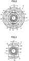
- FIG. 2 is a cross sectional view of a differential casing of the differential gear device of FIG. 1 , as seen in a direction of arrows II-II of FIG. 1 ;
- FIG. 3 is a cross sectional view of the differential casing, as seen in a direction of arrows III-III of FIG. 1 ;
- FIG. 4 is a schematic perspective view of the differential casing of the differential gear device of FIG. 1 ;
- FIG. 5 is a front elevational view of a bearing portion of a differential casing of a differential gear device according to another embodiment of this invention, as seen in a direction toward a seating surface of the bearing portion;
- FIG. 6 is a front elevational view of a bearing portion of a differential casing of a differential gear device according to a further embodiment of the invention, as seen in a direction toward a seating surface of the bearing portion;
- FIG. 7 is a front elevational view of a bearing portion of a differential casing of a differential gear device according to a yet further embodiment of the invention, as seen in a direction toward a seating surface of the bearing portion;
- FIG. 8 is a front elevational view of a bearing portion of a differential casing of a differential gear device according to a still further embodiment of the invention, as seen in a direction toward a seating surface of the bearing portion;
- FIG. 9 is a front elevational view of a bearing portion of a differential casing of a differential gear device according to a yet further embodiment of the invention, as seen in a direction toward a seating surface of the bearing portion;
- FIG. 10 is a front elevational view of a bearing portion of a differential casing of a differential gear device according to yet another embodiment of the invention, as seen in a direction toward a seating surface of the bearing portion;
- FIG. 11 is a front elevational view of a bearing portion of a differential casing of a differential gear device according to still another further embodiment of the invention, as seen in a direction toward a seating surface of the bearing portion.
- the differential gear device according to the present invention is suitably used for a vehicle provided with a transaxle wherein the differential gear device is accommodated within a transaxle casing structure, together with a transmission device configured to transmit a vehicle drive force to the differential gear device.
- the differential gear device of the invention may be used for any other type of vehicular power transmitting system, or for any power transmitting system other than the vehicular power transmitting system.
- the differential gear device includes a differential casing a rotary motion of which is transmitted to a pair of side gears through at least one pinion gear.
- the differential gear device may include one pinion gear, it is preferable that the differential gear device includes a plurality of pinion gears.
- the side gears and the at least one pinion gear are bevel gears.
- the differential casing is provided with a differential ring gear as an input gear in the form of a bevel gear, a hypoid gear or cylindrical gear.
- the differential ring gear is formed integrally with or fixed to the differential casing.
- the rotary motion is transmitted to the differential casing through any other rotary motion transmitting means.
- the differential casing may be a one-piece cast structure, or consist of a plurality of parts which are assembled together.
- the pair of bearing portions are formed integrally with the differential casing or fixed to the inner surfaces of the differential casing.
- Each of the bearing portions may be a cylindrical portion having a constant diameter, or a tapered portion (truncated conical portion) the outside diameter of which increases in a direction from its annular seating surface toward its proximal end.
- the at least one protrusion extending radially outwardly of the outer circumference of the annular seating surface of each bearing portion consists of only one protrusion, or a plurality of protrusions which are equiangularly spaced apart from each other in the circumferential direction of the annular seating surface.
- each protrusion is formed so as to extend in parallel to the above-indicated axis.
- each bearing portion may have an equilateral or other polygonal outer profile with its center on the axis.
- the bearing portion has a plurality of protrusions at or adjacent to the apex portions of the polygonal outer profile.
- Each protrusion may be formed so as to extend in the direction of the above-indicated axis from the inner surface of the differential casing to a position of the annular seating surface of the bearing portion, or to a position between the annular seating surface and the back surface of the corresponding side gear, or to a position between the annular seating surface and the inner surface of the differential casing.
- each bearing portion preferably has at least one lubricant groove formed such that an outer end of each of the at least one lubricant groove is located adjacent to a corresponding one of the at least one protrusion and on a downstream side of the protrusion as seen in a primary direction of rotation of the differential casing about the above-indicated axis.
- the annular seating surface need not have the at least one lubricant groove.
- the at least one lubricant groove may be formed so as to be located regardless of the circumferential position of the corresponding protrusion.
- each of the at least one lubricant groove is formed so as to extend between the inner and outer circumferences of the annular seating surface.
- the lubricant groove may be formed such that its inner end is located between the outer and inner circumferences of the annular seating surface.
- each lubricant groove is formed so as to extend from the outer circumference of the annular seating surface, in the radial direction of the annular seating surface having its center on the above-indicated axis.
- the lubricant groove may be formed such that a straight line of linear extension of the lubricant groove is inclined with respect to a straight line parallel to the radial direction of the annular seating surface, such that the inner end of the lubricant groove may be located at a circumferential position downstream or upstream of a position lying on the straight line parallel to the radial direction, as seen in the primary direction of rotation of the differential casing.
- the lubricant groove may be formed along a curved line.
- annular washer and an annular coned-disc spring are interposed between the annular seating surface of each bearing portion and the back surface of the corresponding side gear.
- only one of the washer and coned-disc spring may be interposed between the annular seating surface and the back surface, and any other member may be interposed therebetween.
- the back surface of the side gear may be held in direct contact with the annular seating surface, without the washer and coned-disc spring.
- the differential casing has a pair of bores which have their centerline on the above-indicated axis and through which rotary shafts connected to the respective side gears are inserted for rotation with the side gears.
- These bores preferably have spiral grooves formed in their inner circumferential surfaces, so that the lubricant oil outside the differential casing is introduced into the differential casing through the spiral grooves, during rotation of the differential casing relative to the rotary shafts in the primary direction of rotation of the differential casing.
- these spiral grooves need not be provided.
- FIG. 1 is the cross sectional view of a differential gear device 10 constructed according to one embodiment of this invention, which is taken in a plane including an axis S.
- FIGS. 2-4 are the views showing the differential casing 12 which is a major component of the differential gear device 10 .
- FIG. 2 is the cross sectional view of the differential casing 12 , as seen in the direction of arrows II-II of FIG. 1
- FIG. 3 is the cross sectional view of the differential casing 12 , as seen in the direction of arrows III-III of FIG. 1
- FIG. 4 is the schematic perspective view of the differential casing 12 .
- this differential gear device 10 is a differential gear device for a transaxle of a vehicle, which is accommodated within a transaxle casing structure, together with a transmission device.
- the differential gear device 10 includes the differential casing 12 rotatable about the axis S, and a pair of side gears 14 L and 14 R which are disposed within the differential casing 12 such that the side gears 14 L and 14 R are rotatable about the axis S and axially opposed to each other.
- the differential gear device 10 is configured such that a rotary motion of the differential casing 12 about the axis S is transmitted to the side gears 14 L and 14 R through two pinion gears 16 , so as to permit differential rotary motions of the side gears 14 L and 14 R.
- the differential gear device 10 is disposed within the vehicular transaxle casing structure such that the axis S is substantially parallel to the width direction of the vehicle and extends in a substantially horizontal direction.
- the transaxle casting structure accommodates a lubricant oil such that the differential gear device 10 is partially immersed in the lubricant oil, so that various components are lubricated with the lubricant oil splashed up by rotary motions of the differential casing 12 and other components of the vehicular transaxle.
- the differential casing 12 is a one-piece cast structure, for example, and has an integrally formed and outwardly extending flange 18 , and is rotated about the axis S with a vehicle drive force transmitted thereto from the transmission device through a differential ring gear 20 fixed to the flange 18 with bolts (not shown).
- the differential ring gear 20 takes the form of a ring, and functions as an input rotary member of the differential gear device 10 .
- the flange 18 has plurality of (i.e. ten in this embodiment) bolt holes 22 through which the bolts extend to fix the differential ring gear 20 to the differential casing 12 .
- the pair of side gears 14 L and 14 R are spline-connected to left and right axles 24 L and 24 R, so that the axles 24 L and 24 R are rotated together with the side gears 14 L and 14 R when the differential casing 12 is rotated.
- the side gears 14 L and 14 R have center bores the inner circumferential surfaces of which are splined for connection to the axles 24 L and 24 R.
- the axles 24 L and 24 R are output rotary shafts of the differential gear device 10 .
- the differential casing 12 has a pair of journals 30 and 32 as its opposite end portions as seen in the direction of the axis S, and a pair of connecting portions 34 and 36 connecting the journals 30 and 32 respectively.
- the differential casing 12 as a whole is a hollow structure disposed within the transaxle casing such that the differential casing 12 is rotatable about the axis S relative to the transaxle casing at its journals 30 and 32 .
- the journals 30 and 32 have respective bores 38 L and 38 R through which the respective axles 24 L and 24 R extend.
- Each of the pair of connecting portions 34 and 36 has a generally arcuate shape having an arcuate outer surface which is curved about the axis S.
- the two connecting portions 34 and 36 are located symmetrically with each other with respect to the axis S, and cooperate to define a pair of windows 40 and 42 therebetween. These windows 40 and 42 are formed to permit a bevel-gear type differential mechanism, namely, the pair of side gears 14 L and 14 R and the pair of pinion gears 16 to be installed and assembled together within the differential casing 12 .
- a pinion shaft 44 extends through the two connecting portions 34 and 36 , so as to intersect with the axis S.
- the pair of pinion gears 16 are mounted on the pinion shaft 44 such that the pinion gears 16 are facing each other, are rotatable relative to the pinion shaft 44 and are held in meshing engagement with the pair of side gears 14 L and 14 R.
- the differential casing 12 has a pair of bearing portions 60 L and 60 R which extend from its respective inner surfaces, toward back surfaces 50 L and 50 R of the respective side gears 14 L and 14 R which are opposed to the above-indicated inner surface in the direction of the axis S.
- the bearing portions 60 L and 60 R are formed integrally with the differential casing 12 , coaxially with the respective side gears 14 L and 14 R, so as to receive axial loads from the side gears 60 L and 60 R.
- the side gears 14 L and 14 R include respective cylindrical portions 52 L and 52 R extending in their axial directions opposite to each other and away from each other, such that the cylindrical portions 52 L and 52 R are located radially inwardly of the respective back surfaces 50 L and 50 R.
- the bearing portions 60 L and 60 R are relatively thick-walled cylindrical portions of the differential casing 12 , which are located radially outwardly of the respective cylindrical portions 52 L and 52 R.
- the bearing portions 60 L and 60 R have respective annular seating surfaces 64 L and 64 R which receive the axial loads from the respective side gears 14 L and 14 R.
- the annular seating surfaces 64 L and 64 R are coaxial with the side gears 14 L and 14 R and perpendicular to the axis S.
- Axial dimensions of the two bearing portions 60 L and 60 R in the direction of the axis S, that is, axial dimensions between the inner surfaces 62 L and 62 R of the differential casing 12 and the annular seating surfaces 64 L and 64 R are slightly different from each other, but are both small.
- the bearing portions 60 L and 60 R are tapered portions the outside diameter of which slightly increases in an axial direction from the annular seating surfaces 64 L and 64 R toward the inner surfaces 62 L and 62 R
- the bearing portions 60 L and 60 R may be cylindrical portions having a constant outside diameter.
- respective annular washers 54 L and 54 R and respective annular coned-disc springs 56 L and 56 R there are interposed respective annular washers 54 L and 54 R and respective annular coned-disc springs 56 L and 56 R, such that the washer 54 L and the coned-disc spring 56 L are superposed on each other while the washer 54 R and the coned-disc spring 56 R are superposed on each other. Hatched lines of a shorter interval in FIGS. 2 and 3 indicate the annular seating surfaces 64 L and 64 R of the bearing portions 60 L and 60 R.
- the bores 38 L and 38 R of the journals 30 and 32 have inner circumferential surfaces each having two spiral grooves 70 L, 70 R through which the lubricant oil outside the differential casing 12 is introduced into the differential casing 12 , during a rotary motion of the differential casing 12 in a primary rotating direction A of rotation relative to the axles 24 L and 24 R.
- the differential casing 12 is rotated in the primary rotating direction A when the vehicle is driven in the forward direction.
- the primary rotating direction A is the clockwise direction as seen in the leftward direction in FIG. 1 .
- the spiral grooves 70 R of the right bore 38 R are formed like a left-handed screw, while the spiral grooves 70 L of the left bore 38 L are formed like a right-handed screw.
- a portion of the lubricant oil introduced into the differential casing 12 through the spiral grooves 70 L and 70 R is used to lubricate spline-connecting portions between the side gears 14 L and 14 R and the axles 24 L and 24 R.
- Another portion of the lubricant oil introduced into the differential casing 12 flows through gaps between the differential casing 12 and the side gears 14 L and 14 R, and is supplied in between the back surfaces 50 L and 50 R and the annular seating surfaces 64 L and 64 R, to lubricate the washers 54 L and 54 R and the coned-disc springs 56 L and 56 R.
- each of the bearing portions 60 L and 60 R has two protrusions 72 L, 72 R as a form of ribs which extend from an outer circumference of the corresponding annular seating surface 64 L, 64 R in the radially outward direction of the annular seating surface 64 L, 64 R.
- the two protrusions 72 L, 72 R are located symmetrically with each other with respect to the axis S.
- the protrusions 72 L, 72 R have an axial dimension in the direction of the axis S, which is equal to an axial dimension of the corresponding bearing portion 60 L, 60 R from the corresponding inner surface 62 L, 62 R to the annular seating surface 64 L, 64 R which are opposed to the back surface 50 L, 50 R of the corresponding side gear 14 L, 14 R.
- the protrusions 72 L and 72 R linearly extend from the corresponding inner surface 62 L, 62 R toward the corresponding side gear 14 L, 14 R along the axis S.
- the lubricant oil accommodated within the differential casing 12 is splashed up by the protrusions 72 L and 72 R when the protrusions 72 L and 72 R are immersed in the lubricant oil, that is, moved below an oil level L (indicated in FIG. 2 ) of the lubricant oil, during a rotary motion of the differential casing 12 .
- the splashed lubricant oil falls down in between the back surfaces 50 L and 50 R of the side gears 14 L and 14 R and the annular seating surfaces 64 L and 64 R of the bearing portions 60 L and 60 R, so that the washers 54 L and 54 R and the coned-disc springs 56 L and 56 R are lubricated with the lubricant oil.
- Each of the annular seating surfaces 64 L and 64 R has two lubricant grooves 74 L, 74 R formed to extend from its outer circumference to its inner circumference of the annular seating surfaces 64 L, 64 R such that an outer end of each of the two lubricant grooves 74 L, 74 R is located downstream of the corresponding one of the two protrusions 72 L, 72 R as seen in the primary rotating direction A.
- Straight lines of linear extension of the lubricant grooves 74 L, 74 R between the outer and inner circumferences of the annular seating surface 64 L, 64 R are inclined with respect to straight lines parallel to the radial direction of the annular seating surface 64 L, 64 R having its center on the axis S, such that the inner end of the lubricant groove 74 L, 74 R is located at a circumferential position downstream of a position lying on the straight line parallel to the radial direction, as seen in the primary rotating direction A.
- the two lubricant grooves 74 L, 74 R are formed substantially parallel to each other.
- Each of the lubricant grooves 74 L and 74 R is substantially Vee-shaped in cross section in a plane perpendicular to the annular seating surface 64 L, 64 R, and has a depth which decreases in a direction from its outer end on the side of the corresponding protrusion 72 L, 72 R to its inner end on the side remove from the protrusion 72 L, 72 R.
- the lubricant grooves 74 L and 74 R may have any other cross sectional shape determined as needed.
- the differential gear device 10 is configured such that each of the pair of bearing portions 60 L and 60 R of the differential casing 12 has the protrusions 72 L, 72 R extending from the outer circumference of the corresponding annular seating surface 64 L, 64 R in the radially outward direction of the annular seating surface 64 L, 64 R, so that the lubricant oil within the differential casing 12 is effectively splashed up by the protrusions 72 L and 72 R of the bearing portions 60 L and 60 R and supplied in between the seating surfaces 64 L and 64 R and the back surfaces 50 L and 50 R of the side gears 14 L and 14 R, even in an early stage of the rotary motion of the differential casing 12 .
- the present differential gear device 10 permits effective splashing of the lubricant oil by the protrusions 72 L, 72 R during rotation of the differential casing 12 , and sufficient lubrication between the back surface 50 L, 50 R of the side gear 14 L, 14 R and the seating surface 64 L, 64 R of the differential casing 12 , even on the side of the side gear 14 L, 14 R which is held stationary in the differential state of the differential gear device 10 .
- the lubricant oil Since the lubricant oil is splashed up by the protrusions 72 L and 72 R provided on the bearing portions 60 L and 60 R, the lubricant oil can be efficiently supplied to and around the seating surfaces 64 L and 64 R, so that a power loss due to the splashing of the lubricant oil can be minimized. Although the amount of supply of the lubricant oil through the spiral grooves 70 L and 70 R is reduced when the lubricant oil has a low temperature, and a high degree of viscosity and an accordingly low degree of fluidity.
- the splashing of the lubricant oil by the protrusions 72 L and 72 R permits a sufficient amount of supply of the lubricant oil even at a low temperature of the lubricant oil, and reduces a risk of shortage of supply of the lubricant oil in between the seating surfaces 64 L and 64 R and the back surfaces 50 L and 50 R of the side gears 14 L, 14 R.
- the power loss due to the splashing of the lubricant oil by the differential ring gear 20 and the other components of the differential gear device 10 can be reduced by lowering the oil level L of the lubricant oil within the differential casing 12 , to an extent which permits the protrusions 72 L and 72 R of the bearing portions 60 L and 60 R to be immersed in the lubricant oil.
- the present embodiment is further configured such that the annular seating surface 64 L, 64 R of each of the bearing portions 60 L and 60 R has the two lubricant grooves 74 L and 74 R formed so as to extend from its outer circumference toward its inner circumference, such that the outer end of the lubricant groove 64 L, 64 R is located adjacent to the corresponding protrusion 72 L, 72 R and on the downstream side of the protrusion 72 L, 72 R as seen in the primary rotating direction A of rotation of the differential casing 12 about the axis S.
- the flows of the lubricant oil are stopped by the protrusions 72 L, 72 R and are easily introduced into the lubricant grooves 74 L and 74 R, so that the lubricant oil is efficiently supplied between the seating surfaces 64 L, 64 R and the respective back surfaces 50 L, 50 R of the side gears 14 L, 14 R.
- each of the two lubricant grooves 74 L, 74 R is formed along the straight line which is inclined with respect to the straight line parallel to the radial direction of the annular seating surface 64 L, 64 R having its center on the axis S, so that the lubricant oil introduced radially inwardly of the annular seating surface 64 L, 64 R is brought into contact with wall surfaces of the lubricant grooves 74 L, 74 R while the inwardly introduced lubricant oil is subjected to a centrifugal force which causes the lubricant oil to be scattered radially outwardly of the annular seating surface 64 L, 64 R, whereby the radially outward scattering of the lubricant oil is suppressed to permit adequate lubrication of the back surface 50 L, 50 R of the side gear 14 L, 14 R and the annular seating surface 64 L, 64 R.
- each of the bearing portions 60 L, 60 R has the two protrusions 72 L, 72 R which are spaced apart from each other in the circumferential direction of the corresponding annular seating surface 64 L, 64 R having its center on the axis S, so that the lubricant oil can be efficiently splashed up by the protrusions 72 L, 72 R and supplied between the corresponding annular seating surface 64 L, 64 R and the back surface 50 L, 50 R of the corresponding side gear 14 L, 14 R.
- the present embodiment is also configured such that the annular washer 54 L, 54 R and the coned-disc spring 56 L, 56 R are interposed between the back surface 50 L, 50 R of each side gear 50 L, 50 R and the annular seating surface 64 L, 64 R of the corresponding bearing portion 60 L, 60 R.
- the components of the differential gear device 10 have a comparatively large total surface area that should be lubricated with the lubricant oil, so that a comparatively large amount of the lubricant oil is required to be supplied to the components.
- the required amount of the lubricant oil can be supplied to the components, by suitably determining the number, distance of extension and shape of the protrusions 72 L and 72 R.
- FIGS. 5-11 are the front elevational views showing different configurations of a bearing portion according to the other embodiments of this invention, which bearing portion is formed integrally with the inner surface 62 L of the differential casing 12 , to receive an axial load from the side gear 14 L.
- Each of these front elevational views corresponds to that of FIG. 2 , and is the elevational view as seen in the direction toward the seating surface 64 L.
- the bearing portion on the side of the side gear 14 R in the following embodiments will not be described, since this bearing portion is identical and symmetrical with the bearing portion on the side of the side gear 14 L similar to FIG. 3 .
- the bearing portion 80 L according to the second embodiment of FIG. 5 has lubricant grooves 82 L each of which is formed so as to extend in the radial direction of the annular seating surface 64 L having its center on the axis S, between the outer and inner circumferences of the annular seating surface 64 L, and the bearing portion 90 L according to the third embodiment of FIG.
- lubricant grooves 92 L formed such that straight lines of linear extension of the lubricant grooves 92 L between the outer and inner circumferences of the annular seating surface 64 L, 64 R are inclined with respect to straight lines parallel to the radial direction of the annular seating surface 64 L, 64 R having its center on the axis S, more specifically, such that the inner end of each of the lubricant grooves 74 L is located at a circumferential position upstream of a position lying on the straight line parallel to the radial direction, as seen in the primary rotating direction A.
- the bearing portion 100 L according to the fourth embodiment of FIG. 7 does not have lubricant grooves 74 L formed in its annular seating surface 64 L.
- the lubricant oil is splashed up by the protrusions 72 L, and is supplied in between the annular seating surface 64 L and the back surface 50 L of the side gear 14 L.
- the bearing portion 110 L according to the fifth embodiment of FIG. 8 has an equilateral hexagonal outer profile, and six protrusions 112 L which are formed at respective six apex portions of the hexagonal outer profile.
- the six protrusions 112 L which extend radially outwardly of the annular seating surface 64 L, correspond to the protrusions 72 L in the preceding embodiments.
- the bearing portion 110 L has six lubricant grooves 114 L which extend from positions located adjacent to and downstream of the apexes of the respective six protrusions 112 L in the primary rotating direction A of the differential casing 12 .
- the six lubricant grooves 114 L extend from the above-indicated positions to the inner circumference of the annular seating surface 64 L, in the radial direction of the annular seating surface 64 L, along respective straight lines passing the axis S.
- the lubricant oil is splashed up by the protrusions 112 L during rotation of the differential casing 12 , and the splashed lubricant oil is introduced into the lubricant grooves 114 L to permit efficient lubrication between the seating surface 64 L and the back surface 50 L of the side gear 14 L.
- the present embodiment has substantially the same advantages as the preceding embodiments.
- the bearing portion 120 L according to the sixth embodiment of FIG. 9 has an equilateral pentagonal outer profile, and five protrusions 122 L which are formed at respective five apex portions of the pentagonal outer profile.
- the five protrusions 122 L extend radially outwardly of the annular seating surface 64 L.
- the bearing portion 120 L has five lubricant grooves 124 L which extend from positions located adjacent to and downstream of the apexes of the respective five protrusions 122 L in the primary rotating direction A of the differential casing 12 .
- the five lubricant grooves 124 L extend from the above-indicated positions to the inner circumference of the annular seating surface 64 L, in the radial direction of the annular seating surface 64 L, along respective straight lines passing the axis S.
- the bearing portion 120 L according to this sixth embodiment has substantially the same advantages as the bearing portion 110 L according to the fifth embodiment of FIG. 8 .
- the bearing portion of the differential casing 12 according to this invention may have any other polygonal outer profile such as triangular, square and heptagonal outer profiles.
- the bearing portion 130 L according to the seventh embodiment of FIG. 10 has eight protrusions 132 L each in the form of a flat plate extending from the outer circumference of the annular seating surface 64 L in the radially outward direction.
- the flat plate which has parallel opposite surfaces parallel to the axis S, is formed integrally with, or fixed to the bearing portion 130 L.
- the eight protrusions 132 L provided to function to splash up the lubricant are equiangularly spaced apart from each other in the circumferential direction of the annular seating surface 64 L.
- the bearing portion 130 L has eight lubricant grooves 134 L which extend from positions located adjacent to and downstream of the respective eight protrusions 132 L in the primary rotating direction A of the differential casing 12 .
- the eight lubricant grooves 134 L extend from the above-indicated positions to the inner circumference of the annular seating surface 64 L, in the radial direction of the annular seating surface 64 L, along respective straight lines passing the axis S.
- the present seventh embodiment has substantially the same advantages as the preceding embodiments. It is noted that the number of the protrusions 132 L may be selected as desired.
- the bearing portion 140 L according to the eight embodiment of FIG. 11 has eight protrusions 142 L. Unlike the protrusions 132 L of the bearing portion 130 L of FIG. 10 , the protrusions 142 L are curved in the primary rotating direction A of rotation of the differential casing 12 , as the protrusions 142 L extend radially outwardly of the annular seating surface 64 L. Accordingly, the flows of the lubricant oil are adequately stopped and efficiently splashed up by the protrusions 142 L during rotation of the bearing portion 140 L together with the differential casing 12 in the primary rotating direction A, and introduced into lubricant grooves 134 L formed in the annular seating surface 64 L. It is noted that the protrusions 142 L may be otherwise shaped, for instance, may extend linearly in directions inclined with respect to the radial direction on the downstream side as seen in the primary rotating direction A.
- the lubricant grooves 114 L, 124 L and 134 L are formed so as to extend from the outer circumference of the annular seating surface 64 L in its radial direction, along straight lines passing the axis S.
- the lubricant grooves 114 L, 124 L and 134 L may be formed along straight lines which are inclined with respect to the straight lines parallel to the radial direction such that the inner ends of the lubricant grooves 114 L, 124 L and 134 L are located at circumferential positions downstream or upstream of the positions lying on the straight lines parallel to the radial direction, as seen in the primary rotating direction A as shown in FIGS. 2 and 6 respectively.
- the lubricant grooves 114 L, 124 L and 134 L may be eliminated, as in the embodiment of FIG. 7 .
- the bearing portions 110 L and 120 L of FIGS. 8 and 9 may be provided with additional protrusions like the protrusions 132 L or 142 L of FIGS. 10 and 11 , at the apex portions of the hexagonal or pentagonal outer profile, in addition to the protrusions 112 L, 122 L.
Landscapes
- Engineering & Computer Science (AREA)
- General Engineering & Computer Science (AREA)
- Mechanical Engineering (AREA)
- General Details Of Gearings (AREA)
- Retarders (AREA)
Abstract
Description
- 10: differential gear device
- 12: differential casing
- 14L, 14R: side gears
- 16: pinion gears
- 50L, 50R: back surfaces
- 54L, 54R: washers
- 56L, 56R: coned-disc springs
- 60L, 60R, 80L, 90L, 100L, 110L, 120L, 130L, 140L: bearing portions
- 62L, 62R: inner surfaces
- 64L, 64R: seating surfaces
- 72L, 72R, 112L, 122L, 132L, 142L: protrusions
- 74L, 74R, 82L, 92L, 114L, 124L, 134L: lubricant grooves
- S: axis
- A: primary rotating direction
- L: oil level
Claims (6)
Applications Claiming Priority (2)
| Application Number | Priority Date | Filing Date | Title |
|---|---|---|---|
| JP2017-234713 | 2017-12-06 | ||
| JP2017234713A JP2019100504A (en) | 2017-12-06 | 2017-12-06 | Differential device |
Publications (2)
| Publication Number | Publication Date |
|---|---|
| US20190170241A1 US20190170241A1 (en) | 2019-06-06 |
| US10663055B2 true US10663055B2 (en) | 2020-05-26 |
Family
ID=66657900
Family Applications (1)
| Application Number | Title | Priority Date | Filing Date |
|---|---|---|---|
| US16/211,340 Expired - Fee Related US10663055B2 (en) | 2017-12-06 | 2018-12-06 | Differential gear device |
Country Status (3)
| Country | Link |
|---|---|
| US (1) | US10663055B2 (en) |
| JP (1) | JP2019100504A (en) |
| CN (1) | CN109882564A (en) |
Cited By (4)
| Publication number | Priority date | Publication date | Assignee | Title |
|---|---|---|---|---|
| US20210388892A1 (en) * | 2019-03-26 | 2021-12-16 | Musashi Seimitsu Industry Co., Ltd. | Differential device |
| US11300189B2 (en) * | 2018-01-18 | 2022-04-12 | Musashi Seimitsu Industry Co., Ltd. | Differential device |
| US20220268346A1 (en) * | 2019-08-02 | 2022-08-25 | Musashi Seimitsu Industry Co., Ltd. | Differential device |
| US20220349464A1 (en) * | 2019-06-06 | 2022-11-03 | Hitachi Astemo, Ltd. | Differential case |
Families Citing this family (5)
| Publication number | Priority date | Publication date | Assignee | Title |
|---|---|---|---|---|
| FR3041055B1 (en) * | 2015-09-16 | 2017-10-06 | Jtekt Europe Sas | GEAR REDUCER WITH INTEGRATED GREASE FOR POWER STEERING |
| JP2019011849A (en) * | 2017-06-30 | 2019-01-24 | トヨタ自動車株式会社 | Differential device for vehicle |
| JP6975075B2 (en) * | 2018-03-01 | 2021-12-01 | 本田技研工業株式会社 | Differential device |
| JP7405523B2 (en) * | 2019-06-28 | 2023-12-26 | 武蔵精密工業株式会社 | transmission device |
| USD1040201S1 (en) * | 2022-03-28 | 2024-08-27 | Marco Fenu | Cover for a bearing housing |
Citations (6)
| Publication number | Priority date | Publication date | Assignee | Title |
|---|---|---|---|---|
| US3490312A (en) * | 1968-05-31 | 1970-01-20 | Gen Motors Corp | Expansible chamber device with hydrodynamic bearing pump and limited slip differential employing same |
| US5007885A (en) * | 1987-08-03 | 1991-04-16 | Toyoda Koki Kabushiki Kaisha | Driving torque transmitting device |
| JPH07305757A (en) | 1994-05-12 | 1995-11-21 | Toyota Motor Corp | Lubricating device for differential gear device for vehicle |
| JP2014190528A (en) | 2013-03-28 | 2014-10-06 | Aisin Aw Co Ltd | Power transmission device |
| JP2017116035A (en) | 2015-12-25 | 2017-06-29 | トヨタ自動車株式会社 | Lubrication structure of differential gear device |
| US10309521B2 (en) * | 2015-12-22 | 2019-06-04 | Jtekt Corporation | Driving-force distribution device |
Family Cites Families (3)
| Publication number | Priority date | Publication date | Assignee | Title |
|---|---|---|---|---|
| JPH0680943U (en) * | 1993-04-28 | 1994-11-15 | ダイハツ工業株式会社 | Differential device |
| JP2004286194A (en) * | 2003-03-25 | 2004-10-14 | Nissan Motor Co Ltd | Differential case and differential device |
| JP5853665B2 (en) * | 2011-12-16 | 2016-02-09 | トヨタ自動車株式会社 | Vehicle differential device |
-
2017
- 2017-12-06 JP JP2017234713A patent/JP2019100504A/en active Pending
-
2018
- 2018-12-04 CN CN201811473017.3A patent/CN109882564A/en not_active Withdrawn
- 2018-12-06 US US16/211,340 patent/US10663055B2/en not_active Expired - Fee Related
Patent Citations (6)
| Publication number | Priority date | Publication date | Assignee | Title |
|---|---|---|---|---|
| US3490312A (en) * | 1968-05-31 | 1970-01-20 | Gen Motors Corp | Expansible chamber device with hydrodynamic bearing pump and limited slip differential employing same |
| US5007885A (en) * | 1987-08-03 | 1991-04-16 | Toyoda Koki Kabushiki Kaisha | Driving torque transmitting device |
| JPH07305757A (en) | 1994-05-12 | 1995-11-21 | Toyota Motor Corp | Lubricating device for differential gear device for vehicle |
| JP2014190528A (en) | 2013-03-28 | 2014-10-06 | Aisin Aw Co Ltd | Power transmission device |
| US10309521B2 (en) * | 2015-12-22 | 2019-06-04 | Jtekt Corporation | Driving-force distribution device |
| JP2017116035A (en) | 2015-12-25 | 2017-06-29 | トヨタ自動車株式会社 | Lubrication structure of differential gear device |
Cited By (6)
| Publication number | Priority date | Publication date | Assignee | Title |
|---|---|---|---|---|
| US11300189B2 (en) * | 2018-01-18 | 2022-04-12 | Musashi Seimitsu Industry Co., Ltd. | Differential device |
| US20210388892A1 (en) * | 2019-03-26 | 2021-12-16 | Musashi Seimitsu Industry Co., Ltd. | Differential device |
| US20220349464A1 (en) * | 2019-06-06 | 2022-11-03 | Hitachi Astemo, Ltd. | Differential case |
| US11674588B2 (en) * | 2019-06-06 | 2023-06-13 | Hitachi Astemo, Ltd. | Differential case |
| US20220268346A1 (en) * | 2019-08-02 | 2022-08-25 | Musashi Seimitsu Industry Co., Ltd. | Differential device |
| US11655888B2 (en) * | 2019-08-02 | 2023-05-23 | Musashi Saimitsu Industry Co., Ltd. | Differential device |
Also Published As
| Publication number | Publication date |
|---|---|
| JP2019100504A (en) | 2019-06-24 |
| CN109882564A (en) | 2019-06-14 |
| US20190170241A1 (en) | 2019-06-06 |
Similar Documents
| Publication | Publication Date | Title |
|---|---|---|
| US10663055B2 (en) | Differential gear device | |
| US8932170B2 (en) | Planetary gear device | |
| JP4930453B2 (en) | Bearing lubrication structure of rotating shaft | |
| CN109944917B (en) | Axle assembly including differential assembly having reverse differential bearings | |
| US8167758B2 (en) | Drive axle assembly with gear mesh lubrication systems for lubricating gear mesh and/or differential bearings | |
| US9347542B2 (en) | Parallel-axis helical differential assembly | |
| US10760674B2 (en) | Power transmission apparatus | |
| US10408336B2 (en) | Differential apparatus | |
| US6053835A (en) | Differential gear lubrication structure | |
| KR20120030060A (en) | Limited slip differential with positive lube flow to clutch plates | |
| JP2005282859A (en) | Oil propulsion wheel and shaft for power transmission device | |
| US11300155B2 (en) | Cage for a tapered roller bearing and tapered roller bearing | |
| CN110578782A (en) | Transmission shaft of differential mechanism and differential mechanism | |
| CN111503251A (en) | Lubricating structure of differential device | |
| JP2017116035A (en) | Lubrication structure of differential gear device | |
| US8152382B2 (en) | Output tube assembly for drive axle covers and method of use | |
| EP1522768A2 (en) | Differential gearing for vehicle | |
| JP2015052374A (en) | Lubrication structure of power transmission device for vehicle | |
| RU98796U1 (en) | DIFFERENTIAL | |
| JP6851917B2 (en) | Power transmission device | |
| US10385962B2 (en) | Direct lubricating input shaft assembly | |
| JP2021008905A (en) | Differential case | |
| JP2003097675A (en) | Lubricating structure of bearing for drive pinion shaft | |
| JP7504076B2 (en) | Differential gear | |
| JP2018168963A (en) | Differential |
Legal Events
| Date | Code | Title | Description |
|---|---|---|---|
| FEPP | Fee payment procedure |
Free format text: ENTITY STATUS SET TO UNDISCOUNTED (ORIGINAL EVENT CODE: BIG.); ENTITY STATUS OF PATENT OWNER: LARGE ENTITY |
|
| STPP | Information on status: patent application and granting procedure in general |
Free format text: APPLICATION DISPATCHED FROM PREEXAM, NOT YET DOCKETED |
|
| AS | Assignment |
Owner name: TOYOTA JIDOSHA KABUSHIKI KAISHA, JAPAN Free format text: ASSIGNMENT OF ASSIGNORS INTEREST;ASSIGNORS:NAKAMURA, SHINGO;HORI, TETSUO;UENO, YUTAKA;AND OTHERS;REEL/FRAME:048273/0186 Effective date: 20181128 |
|
| STPP | Information on status: patent application and granting procedure in general |
Free format text: DOCKETED NEW CASE - READY FOR EXAMINATION |
|
| ZAAA | Notice of allowance and fees due |
Free format text: ORIGINAL CODE: NOA |
|
| ZAAB | Notice of allowance mailed |
Free format text: ORIGINAL CODE: MN/=. |
|
| STPP | Information on status: patent application and granting procedure in general |
Free format text: PUBLICATIONS -- ISSUE FEE PAYMENT VERIFIED |
|
| STCF | Information on status: patent grant |
Free format text: PATENTED CASE |
|
| FEPP | Fee payment procedure |
Free format text: MAINTENANCE FEE REMINDER MAILED (ORIGINAL EVENT CODE: REM.); ENTITY STATUS OF PATENT OWNER: LARGE ENTITY |
|
| STCH | Information on status: patent discontinuation |
Free format text: PATENT EXPIRED DUE TO NONPAYMENT OF MAINTENANCE FEES UNDER 37 CFR 1.362 |
|
| FP | Lapsed due to failure to pay maintenance fee |
Effective date: 20240526 |