US10659727B2 - Device and method for transmitting video signals, and system for playing video signals - Google Patents
Device and method for transmitting video signals, and system for playing video signals Download PDFInfo
- Publication number
- US10659727B2 US10659727B2 US15/991,196 US201815991196A US10659727B2 US 10659727 B2 US10659727 B2 US 10659727B2 US 201815991196 A US201815991196 A US 201815991196A US 10659727 B2 US10659727 B2 US 10659727B2
- Authority
- US
- United States
- Prior art keywords
- channel
- signal
- trigger switch
- signal source
- video signals
- Prior art date
- Legal status (The legal status is an assumption and is not a legal conclusion. Google has not performed a legal analysis and makes no representation as to the accuracy of the status listed.)
- Active
Links
Images


Classifications
-
- H—ELECTRICITY
- H04—ELECTRIC COMMUNICATION TECHNIQUE
- H04N—PICTORIAL COMMUNICATION, e.g. TELEVISION
- H04N7/00—Television systems
- H04N7/10—Adaptations for transmission by electrical cable
- H04N7/102—Circuits therefor, e.g. noise reducers, equalisers, amplifiers
- H04N7/104—Switchers or splitters
-
- H—ELECTRICITY
- H04—ELECTRIC COMMUNICATION TECHNIQUE
- H04N—PICTORIAL COMMUNICATION, e.g. TELEVISION
- H04N5/00—Details of television systems
- H04N5/76—Television signal recording
- H04N5/765—Interface circuits between an apparatus for recording and another apparatus
-
- H—ELECTRICITY
- H04—ELECTRIC COMMUNICATION TECHNIQUE
- H04N—PICTORIAL COMMUNICATION, e.g. TELEVISION
- H04N21/00—Selective content distribution, e.g. interactive television or video on demand [VOD]
- H04N21/40—Client devices specifically adapted for the reception of or interaction with content, e.g. set-top-box [STB]; Operations thereof
- H04N21/43—Processing of content or additional data, e.g. demultiplexing additional data from a digital video stream; Elementary client operations, e.g. monitoring of home network or synchronising decoder's clock; Client middleware
- H04N21/436—Interfacing a local distribution network, e.g. communicating with another STB or one or more peripheral devices inside the home
- H04N21/4363—Adapting the video stream to a specific local network, e.g. a Bluetooth® network
- H04N21/43632—Adapting the video stream to a specific local network, e.g. a Bluetooth® network involving a wired protocol, e.g. IEEE 1394
- H04N21/43635—HDMI
-
- H—ELECTRICITY
- H04—ELECTRIC COMMUNICATION TECHNIQUE
- H04N—PICTORIAL COMMUNICATION, e.g. TELEVISION
- H04N5/00—Details of television systems
- H04N5/222—Studio circuitry; Studio devices; Studio equipment
- H04N5/262—Studio circuits, e.g. for mixing, switching-over, change of character of image, other special effects ; Cameras specially adapted for the electronic generation of special effects
- H04N5/268—Signal distribution or switching
-
- H—ELECTRICITY
- H04—ELECTRIC COMMUNICATION TECHNIQUE
- H04N—PICTORIAL COMMUNICATION, e.g. TELEVISION
- H04N5/00—Details of television systems
- H04N5/38—Transmitter circuitry for the transmission of television signals according to analogue transmission standards
-
- H—ELECTRICITY
- H04—ELECTRIC COMMUNICATION TECHNIQUE
- H04N—PICTORIAL COMMUNICATION, e.g. TELEVISION
- H04N5/00—Details of television systems
- H04N5/44—Receiver circuitry for the reception of television signals according to analogue transmission standards
- H04N5/50—Tuning indicators; Automatic tuning control
-
- H—ELECTRICITY
- H04—ELECTRIC COMMUNICATION TECHNIQUE
- H04N—PICTORIAL COMMUNICATION, e.g. TELEVISION
- H04N7/00—Television systems
- H04N7/01—Conversion of standards, e.g. involving analogue television standards or digital television standards processed at pixel level
-
- H—ELECTRICITY
- H04—ELECTRIC COMMUNICATION TECHNIQUE
- H04N—PICTORIAL COMMUNICATION, e.g. TELEVISION
- H04N7/00—Television systems
- H04N7/06—Systems for the simultaneous transmission of one television signal, i.e. both picture and sound, by more than one carrier
- H04N7/066—Systems for the simultaneous transmission of one television signal, i.e. both picture and sound, by more than one carrier the carriers being allocated to more than one television channel
Definitions
- the disclosure relates to the technical field of liquid crystal display, and in particular, to a device and method for transmitting video signals, and a system for playing video signals.
- multimedia sources such as set-top boxes, DVD players, and computers
- video display devices such as televisions
- a display device available the market generally has multiple display interfaces, through which multiple input sources often simultaneously input signals.
- the display device can display only for one specific signal source at a fixed time, thereby causing waste for other signal sources; and also increasing the power consumption of the display device.
- An object of the present disclosure is to provide a device and method for transmitting video signals, and a system for playing video signals, to overcome one or more problems due to limitations and disadvantages of the related art at least to some extent.
- a device for transmitting video signals including:
- a switch control unit configured to determine a target signal channel according to a channel selection signal, and turn on the trigger switch unit corresponding to the target signal channel and turn off the other trigger switch units;
- a signal source control unit disposed at each of the signal sources, and configured to control the operation and standby of the signal source according to the turning on and turning off of the trigger switch unit of the signal channel connected to the signal source.
- the signal channel includes two or more of a DisplayPort channel, a high definition multimedia channel, a digital video channel, and a video graphics array channel.
- the trigger switch unit when the signal channel is a DisplayPort channel, a high definition multimedia channel, or a digital video channel, the trigger switch unit includes a hot plug electronic switch.
- the trigger switch unit when the signal channel is a video graphics array channel, the trigger switch unit includes a plurality of sub-switches corresponding to the respective color channels.
- the trigger switch unit further includes:
- a resistance of each of the impedance matching resistors is 75 ohms.
- the signal source control unit includes:
- a parameter acquisition unit configured to, when the trigger switch unit of the signal channel connected to the signal source at which the signal source control unit is disposed is turned on, acquire parameter information of a display connected to the signal channel;
- a signal conversion unit configured to convert video signals to be transmitted according to the parameter information and transmit the converted video signals to the display via the signal channel.
- the parameter information includes extended display identification data value information of the display.
- the signal channel includes a signal transmission interface and a signal transmission line connecting the signal transmission interface and the signal source.
- a system for playing video signals including a display and the device for transmitting video signals according to any of the above.
- a method for transmitting video signals including:
- the switch control unit to turn on a trigger switch unit corresponding to the target signal channel and turn off the other trigger switch units, and then by providing a signal source control unit to respectively control the operation and standby of the signal sources according to the turning on and turning off of the trigger switch units of the signal channels connected to the signal sources.
- the signal channel corresponding to the target signal channel can keep receiving from the video signal source, while the other signal channels may be in a standby state.
- FIG. 1 schematically shows a block diagram of a device for transmitting video signals.
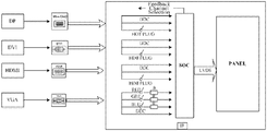
- FIG. 2 schematically shows an example of a device for transmitting video signals.
- FIG. 3 schematically shows a block diagram of another device for transmitting video signals.
- FIG. 4 schematically shows a schematic diagram of connection between a trigger switch unit and an electronic switch in each signal channel.
- FIG. 5 schematically shows a flowchart of a method for transmitting video signals.
- the present exemplary embodiment first provides a device for transmitting video signals.
- the device for transmitting video signals may include: two or more signal channels respectively connected to the signal sources.
- Two or more trigger switch units are respectively disposed corresponding to the signal channels.
- a switch control unit is configured to determine a target signal channel according to a channel selection signal, and turn on a trigger switch unit corresponding to the target signal channel and turn off the other trigger switch units.
- a signal source control unit is disposed at each of the signal sources, and configured to control the operation and standby of the signal source according to the turning on and turning off of the trigger switch unit of the signal channel connected to the signal source.
- the signal channel corresponding to the target signal channel can keep receiving from the video signal source, while the other signal channels may be in a standby state.
- the other signal channels are in a standby state, when the target signal channel is switched, the video signal source of the target signal channel after the switch may be timely switched to the display panel without significantly increasing the latency of the display.
- two or more signal channels 110 may be respectively connected to the signal sources.
- the above signal channel 110 may include a DisplayPort (including a DisplayPort, a Mini DisplayPort and a Micro DisplayPort, etc., which may be selected according to actual needs and is not specifically limited in this example) channel, a high-definition multimedia channel, a digital video channel and a video graphics array channel, etc., or may also include other signal channels, for example, a standard video input (RCA channel) or an S video input channel, etc. which is not is particularly limited.
- the DisplayPort channel (high-definition digital display interface channel) can be used to connect a computer with a display panel or connect a computer with other display device. There is no particular limitation in this example.
- the High Definition Multimedia Interface is a digital video/audio interface technology, and a dedicated digital interface for video transmission that delivers both audio and video signals simultaneously.
- the Digital Visual Interface may improve the quality of the images of the PC monitors through digital transmission of images.
- the Video Graphics Array may have characteristics of high resolution, fast display speed and rich colors, etc.
- the signal channels are respectively connected to the signal sources.
- the signal formats of the video signals provided by the signal sources may be the same, for example, the signal formats of the video signals may be NTSC format (PAL format or SECAM format, which is not limited by this example).
- the signal formats of the video signals provided by the signal sources may also be different.
- the signal formats of the video signals are respectively two or three of the NTSC format, PAL format and SECAM format, which is not limited by the present disclosure.
- the signal channel may include a signal transmission interface 306 and a signal transmission line 308 .
- the signal transmission interface 306 may be connected to the signal source through the signal transmission line 308 .
- the signal transmission interface (refer to Mini Disp, DVI, HDMI and VGA as shown in FIG. 2 ) may be connected to DP, DVI, HDMI, and VGA via the signal transmission line. It should be noted herein that the signal transmission interface 306 and the signal transmission line 308 are all entities, therefore, they are not shown in FIG. 2 .
- the above trigger switch unit 120 may include a plurality of Hot Plug electronic switches or multiple sub-switches.
- the trigger switch unit is a Hot Plug electronic switch.
- the signal channel is a video graphics array channel
- the trigger switch unit is a plurality of sub-switches corresponding to R/G/B color channels in the video graphics array channel.
- the hot-plug or hot-swap switch may be plugged or swapped with power turned on.
- the hot-plug or hot-swap function may include allowing a user to remove and/or replace a damaged hard disk, power source, a card or a board or other component without shutting down the system or turning off the power, so as to improve the quick recovery capability, scalability and flexibility of the system against accidents.
- some disk mirroring systems orienting high-end applications may be provided with hot-plugging capability for the disks.
- the hot plugging may be referred to as hot replacement, hot expansion, or hot upgrade, etc.
- the trigger switch unit may control the signal channel to be in standby state or in operation state through the manner as shown in FIG. 4 .
- the sub-switches provided in the R/G/B color channels in the video graphics array channel may be respectively connected to the pin X 0 , the pin X 1 and the pin X 2 in the trigger switch unit.
- the hot plug detect in the digital video channel may be connected to the pin X 3 in the trigger switch unit.
- the Hot plug detect (HPD) in the DisplayPort channel may be connected to the pin X 4 in the trigger switch unit.
- the HPD/HEAC_N in the high-definition multimedia channel may be connected to pin X 4 in the trigger switch unit.
- each channel may directly determine whether the channel needs to be put into operation or standby through the HPD or the states of the sub-switches.
- each sub-switch is further provided with an impedance matching resistor, and the resistance of the impedance matching resistor may be 75 ohm or other resistance, for example, may be 50 ohm or 100 ohm, and the like, which is not specifically limited in the exemplary embodiment.
- the impedance matching resistor By providing the impedance matching resistor, on one hand, it may improve the matching between the signal source and the signal line in the video graphics array channel and reduce the reflection of the signal channel; on the other hand, the steepness of the signal edge may be reduced, to reduce high-frequency noise and overshoot and so on.
- the above impedance matching resistor may be provided as corresponding to the hot-plug electronic switches, which is not limited in the present disclosure.
- the switch control unit 130 may include a SOC (System on Chip) control chip, and may also include other devices having a control function, such as a microprocessor or a CPU, and the like, which is not limited in the present example.
- the switch control unit 130 may be configured to determine a target signal channel according to the channel selection signal, turn on the trigger switch unit corresponding to the target signal channel and turn off the other trigger switch units.
- an external device which may be a remote control, for example
- select a target signal channel which may be a DisplayPort for example
- a signal receiving device for example, an Infrared Radiation IR receiving device.
- the target signal channel is sent to the SOC.
- the SOC selects a trigger switch unit corresponding to the target signal channel through a feedback channel selection module, and turns on the corresponding signal channel through the trigger switch unit corresponding to the target signal channel.
- the target signal channel determined according to the channel selection signal is the DisplayPort channel
- the Hot Plug electronic switch corresponding to the DisplayPort channel turn on the Hot Plug electronic switch corresponding to the DisplayPort channel, and then turn off the Hot Plug electronic switch corresponding to the high definition multimedia channel
- the above signal source control unit 140 may be disposed at each signal source, and the signal source control unit may be configured to control the operation and standby of the signal source according to the turning on and turning off of the trigger switch unit of the signal channel connected to the signal source.
- the Hot Plug electronic switch corresponding to the DisplayPort channel when the Hot Plug electronic switch corresponding to the DisplayPort channel is in the turned on state and the Hot Plug electronic switch corresponding to the high definition multimedia channel, the Hot Plug electronic switch corresponding to the digital video channel and the sub-switches provided as corresponding to the R/G/B color channels in video graphics array channel are in the turned off state, the signal source corresponding to the DisplayPort channel is controlled to be in the operation state, and the signal sources respectively corresponding to the digital video channel, the high definition multimedia channel, the video graphics array channel are controlled to be in the turned off states.
- the Hot Plug electronic switch corresponding to the high definition multimedia channel When the Hot Plug electronic switch corresponding to the high definition multimedia channel is in the turned on state and the Hot Plug electronic switch corresponding to the DisplayPort channel, the Hot Plug electronic switch corresponding to the digital video channel and the sub-switches provided as corresponding to the R/G/B color channels in video graphics array channel are in the turned off state, the signal source corresponding to the high definition multimedia channel is controlled to be in the operation state, and the signal sources respectively corresponding to the digital video channel, the DisplayPort channel, the video graphics array channel are controlled to be in the turned off states.
- the Hot Plug electronic switch corresponding to the digital video channel When the Hot Plug electronic switch corresponding to the digital video channel is in the turned on state and the Hot Plug electronic switch corresponding to the high definition multimedia channel, the Hot Plug electronic switch corresponding to the DisplayPort channel, and the sub-switches provided as corresponding to the R/G/B color channels in video graphics array channel are in the turned off state, the signal source corresponding to the digital video channel is controlled to be in the operation state, and the signal sources respectively corresponding to the DisplayPort channel, the high definition multimedia channel, the video graphics array channel are controlled to be in the turned off states.
- the signal source corresponding to the video graphics array channel is controlled to be in the operation state, and the signal sources respectively corresponding to the digital video channel, the DisplayPort channel, and the high definition multimedia channel are controlled to be in the turned off states.
- the signal source control unit 140 may further include a parameter acquisition unit 302 and a signal conversion unit 304 .
- the parameter acquisition unit 302 may be configured to, when the trigger switch unit of the signal channel 110 connected to the signal source at which the signal source control unit 140 is disposed is turned on, acquire parameter information of a display connected to the signal channel.
- the signal conversion unit may be configured to convert video signals to be transmitted according to the parameter information and transmit the converted video signals to the display via the signal channel.
- the parameter acquisition unit acquires parameter information of the display connected to the DisplayPort signal channel.
- the parameter information may be Extended Display Identification Data (EDID), which is a VESA standard data format that can include parameters on the monitor and its performance such as vendor information, maximum image size, color settings, manufacturer settings, limits on frequency range, name of the display and serial numbers and so on.
- EDID Extended Display Identification Data
- the signal conversion unit converts the video signals to be transmitted which are received through the DisplayPort signal channel, to a format that the display can support according to the EDID information. Then, the converted video signals are transmitted to the display to be displayed through the DisplayPort signal channel.
- the signal conversion unit may be a direct digital control circuit (DDC) or other modules with a conversion function, which is not limited in this example.
- DDC direct digital control circuit
- the DDC circuit may also include EDID identification, storage, chroma space conversion and other circuit module.
- the DDC circuit is a key component of the system to achieve control functions. The working process is that the DDC circuit acquiring data from video signal source in real time through an analog input channel (AI) and a digital input channel (DI), converting analog signals into digital signals acceptable by a computer (A/D conversion), then performing operation according to a certain control rule, finally, issuing a control signal and converting the digital signals to analog signals (D/A conversion), to directly control the display panel to operate through an analog output channel (AO) and a digital output channel (DO).
- AI analog input channel
- DI digital input channel
- the device for transmitting video signals may further include a low-voltage differential signal unit disposed between the switch control unit and the display and configured to perform noise reduction processing on the converted video signals.
- the low-voltage differential signal unit (Low-Voltage Differential Signaling, LVDS) may be configured to disposed between the SOC control chip and the display panel (Panel), and configured to perform noise reduction processing on the converted video signals and received by the DisplayPort signal channel.
- LVDS Low-Voltage Differential Signaling
- the present disclosure also provides a method for transmitting video signals based on the device for transmitting video signals described above.
- the method for transmitting video signals may include steps S 510 -S 520 .
- step S 510 a target signal channel is determined according to a channel selection signal, and the trigger switch unit corresponding to the target signal channel is turned on and the other trigger switch units are turned off.
- step S 520 the operation and standby of each signal source connected to each of the signal channels are controlled according to turning on and turning off of each of the trigger switch units corresponding to the signal channels.
- step 1 the power of the display 310 is turned on, an external device (which may be a remote control, for example) is used to select a target signal channel (which may be a DisplayPort for example) and send the target signal channel to a signal receiving device (for example, an Infrared Radiation IR receiving device).
- an external device which may be a remote control, for example
- a target signal channel which may be a DisplayPort for example
- a signal receiving device for example, an Infrared Radiation IR receiving device.
- step 2 after the infrared receiving device receives the target signal channel, the target signal channel is sent to the SOC.
- the SOC selects a trigger switch unit corresponding to the target signal channel through a feedback channel selection module, turns on the corresponding signal channel (for example, the DisplayPort channel) through the trigger switch unit (for example, the Hot Plug corresponding to the DisplayPort channel) corresponding to the target signal channel, and turns off the electronic switches (for example, the Hot Plug corresponding to the HDMI, the Hot Plug corresponding to the DVI and the R/G/B sub-switches corresponding to the VGA, etc.) corresponding to the other signal channels (for example, the HDMI channel, the DVI channel and the VAG channel, etc.).
- step 3 when the trigger switch unit corresponding to the signal channel corresponding to the target signal channel is turned on, parameter information (for example, the EDID, Extended Display Identification Data, which may include vendor ID, product ID, serial number, date of manufacture, EDID version, voltage rating of the display, maximum height and width, color characteristics of the display, time sequence of the display, timing and resolution of the display, the data format of the video source supported by the display, etc.) of the above display panel is acquired through the signal source control unit (for example, the DDC control circuit) corresponding to the signal channel.
- the signal source control unit for example, the DDC control circuit
- step 4 the DDC control circuit converts the data format of the video signals received through the above signal channel to a data format supported by the display panel according to the parameter information, and displays the video signals on the above display panel after performing noise reduction processing through the low-voltage differential signal module.
Landscapes
- Engineering & Computer Science (AREA)
- Multimedia (AREA)
- Signal Processing (AREA)
- Computer Networks & Wireless Communication (AREA)
- Two-Way Televisions, Distribution Of Moving Picture Or The Like (AREA)
- Controls And Circuits For Display Device (AREA)
Abstract
Description
Claims (9)
Applications Claiming Priority (3)
| Application Number | Priority Date | Filing Date | Title |
|---|---|---|---|
| CN201710607659.7 | 2017-07-24 | ||
| CN201710607659.7A CN107277417B (en) | 2017-07-24 | 2017-07-24 | Video signal transmission device and method, video signal playback system |
| CN201710607659 | 2017-07-24 |
Publications (2)
| Publication Number | Publication Date |
|---|---|
| US20190028672A1 US20190028672A1 (en) | 2019-01-24 |
| US10659727B2 true US10659727B2 (en) | 2020-05-19 |
Family
ID=60079055
Family Applications (1)
| Application Number | Title | Priority Date | Filing Date |
|---|---|---|---|
| US15/991,196 Active US10659727B2 (en) | 2017-07-24 | 2018-05-29 | Device and method for transmitting video signals, and system for playing video signals |
Country Status (2)
| Country | Link |
|---|---|
| US (1) | US10659727B2 (en) |
| CN (1) | CN107277417B (en) |
Families Citing this family (3)
| Publication number | Priority date | Publication date | Assignee | Title |
|---|---|---|---|---|
| WO2018101514A1 (en) * | 2016-12-01 | 2018-06-07 | 엘지전자 주식회사 | Image display device and image display system comprising same |
| US11404025B2 (en) | 2019-04-10 | 2022-08-02 | Mediatek Inc. | Video processing system for performing artificial intelligence assisted picture quality enhancement and associated video processing method |
| CN117676060B (en) * | 2024-02-01 | 2024-06-11 | 深圳市灰度科技有限公司 | Video signal transmission circuit and system |
Citations (8)
| Publication number | Priority date | Publication date | Assignee | Title |
|---|---|---|---|---|
| US20020026552A1 (en) * | 1998-01-06 | 2002-02-28 | Prasanna M. Shah | System and method for switching signals over twisted-pair wires |
| US6529680B1 (en) * | 1996-04-26 | 2003-03-04 | Mitsubishi Digital Electronics America, Inc. | Device for selecting and controlling a plurality of signal sources in a television system |
| US20040189681A1 (en) * | 2003-02-19 | 2004-09-30 | Naoyuki Itakura | Display device and method of driving same |
| US20100284489A1 (en) * | 2009-05-06 | 2010-11-11 | Postech Academy Industry Foundation | Digital differential signal transmitter for low supply voltage |
| US20110068911A1 (en) * | 2008-05-16 | 2011-03-24 | Axel Nix | System for Providing and Displaying Video Information Using A Plurality of Video Sources |
| US20120023343A1 (en) * | 2010-07-26 | 2012-01-26 | Aseem Gupta | Power and data hub |
| US20160012001A1 (en) * | 2014-07-08 | 2016-01-14 | Good Way Technology Co., Ltd. | Connection interface switching device for multiple portable devices |
| US20180300469A1 (en) * | 2017-04-17 | 2018-10-18 | Wyse Technology L.L.C. | Securing source devices using a display device filter |
Family Cites Families (7)
| Publication number | Priority date | Publication date | Assignee | Title |
|---|---|---|---|---|
| US9307189B2 (en) * | 2012-05-11 | 2016-04-05 | Pioneer Digital Design And Manufacturing Corporation | Relay apparatus controlling signal channel selection |
| CN102695025B (en) * | 2012-05-25 | 2014-07-23 | 浙江一舟电子科技股份有限公司 | HDMI converter |
| CN103414933B (en) * | 2013-07-29 | 2016-12-28 | 华为技术有限公司 | Analog video signal output device and electronic equipment |
| CN203457230U (en) * | 2013-07-30 | 2014-02-26 | 信佶(深圳)电脑配件有限公司 | Channel controllable energy-saving type HDMI distributor |
| CN103595943A (en) * | 2013-11-16 | 2014-02-19 | 京东方科技集团股份有限公司 | Video signal transmission equipment, playing system and video signal transmission method |
| CN106954088B (en) * | 2017-03-07 | 2020-02-04 | 青岛海信电器股份有限公司 | Touch control method and touch control all-in-one machine |
| CN206932323U (en) * | 2017-07-24 | 2018-01-26 | 京东方科技集团股份有限公司 | Video signal transmission device, vision signal play system |
-
2017
- 2017-07-24 CN CN201710607659.7A patent/CN107277417B/en active Active
-
2018
- 2018-05-29 US US15/991,196 patent/US10659727B2/en active Active
Patent Citations (8)
| Publication number | Priority date | Publication date | Assignee | Title |
|---|---|---|---|---|
| US6529680B1 (en) * | 1996-04-26 | 2003-03-04 | Mitsubishi Digital Electronics America, Inc. | Device for selecting and controlling a plurality of signal sources in a television system |
| US20020026552A1 (en) * | 1998-01-06 | 2002-02-28 | Prasanna M. Shah | System and method for switching signals over twisted-pair wires |
| US20040189681A1 (en) * | 2003-02-19 | 2004-09-30 | Naoyuki Itakura | Display device and method of driving same |
| US20110068911A1 (en) * | 2008-05-16 | 2011-03-24 | Axel Nix | System for Providing and Displaying Video Information Using A Plurality of Video Sources |
| US20100284489A1 (en) * | 2009-05-06 | 2010-11-11 | Postech Academy Industry Foundation | Digital differential signal transmitter for low supply voltage |
| US20120023343A1 (en) * | 2010-07-26 | 2012-01-26 | Aseem Gupta | Power and data hub |
| US20160012001A1 (en) * | 2014-07-08 | 2016-01-14 | Good Way Technology Co., Ltd. | Connection interface switching device for multiple portable devices |
| US20180300469A1 (en) * | 2017-04-17 | 2018-10-18 | Wyse Technology L.L.C. | Securing source devices using a display device filter |
Also Published As
| Publication number | Publication date |
|---|---|
| US20190028672A1 (en) | 2019-01-24 |
| CN107277417B (en) | 2023-12-19 |
| CN107277417A (en) | 2017-10-20 |
Similar Documents
| Publication | Publication Date | Title |
|---|---|---|
| US6314479B1 (en) | Universal multi-pin plug and display connector for standardizing signals transmitted between a computer and a display for a PC theatre interconnectivity system | |
| US8284087B2 (en) | System and method for detecting accessory connection and accessory class | |
| US8120612B2 (en) | Intelligent video graphics switcher | |
| US11350158B2 (en) | Electronic device and control method thereof | |
| CN102662514B (en) | A kind of method and mobile terminal of control touch screen | |
| US20070241990A1 (en) | Method for automatically switching video sources to a display device | |
| EP2439924A1 (en) | Extension module and television having the extension module | |
| US9942512B2 (en) | Display apparatus and control method thereof | |
| CN102054469A (en) | Display and display method thereof | |
| US20080165291A1 (en) | Display apparatus for displaying video input through various connectors | |
| US10659727B2 (en) | Device and method for transmitting video signals, and system for playing video signals | |
| TW201539424A (en) | Video switch and switching method thereof | |
| US10645355B2 (en) | Electronic apparatus and controlling method thereof | |
| EP1887794A2 (en) | Portable device integrated with external video signal display function | |
| CN206932323U (en) | Video signal transmission device, vision signal play system | |
| US12468496B2 (en) | Media docking device and media docking method | |
| TWI447671B (en) | Apparatus and method of switching digital/analog video signal and apparatus and method of switching keyboard/monitor/mouse | |
| TWM536826U (en) | Conversion device and conversion system thereof | |
| KR20070083341A (en) | Electronic device control method using digital interface | |
| US20090147144A1 (en) | Television box | |
| CN205545642U (en) | Display screen and spliced screen | |
| CN1355473A (en) | LCD Monitor | |
| KR200396105Y1 (en) | Implementation of Medical Image LCD controller using Multi-Image Equipment | |
| TWM557859U (en) | Video splitter device | |
| KR20180099219A (en) | Electronic device |
Legal Events
| Date | Code | Title | Description |
|---|---|---|---|
| FEPP | Fee payment procedure |
Free format text: ENTITY STATUS SET TO UNDISCOUNTED (ORIGINAL EVENT CODE: BIG.); ENTITY STATUS OF PATENT OWNER: LARGE ENTITY |
|
| AS | Assignment |
Owner name: BOE TECHNOLOGY GROUP CO., LTD., CHINA Free format text: ASSIGNMENT OF ASSIGNORS INTEREST;ASSIGNORS:MA, XITONG;ZENG, QI;ZHAO, TIANYUE;REEL/FRAME:046118/0048 Effective date: 20180204 |
|
| STPP | Information on status: patent application and granting procedure in general |
Free format text: DOCKETED NEW CASE - READY FOR EXAMINATION |
|
| STPP | Information on status: patent application and granting procedure in general |
Free format text: NON FINAL ACTION MAILED |
|
| STPP | Information on status: patent application and granting procedure in general |
Free format text: RESPONSE TO NON-FINAL OFFICE ACTION ENTERED AND FORWARDED TO EXAMINER |
|
| STPP | Information on status: patent application and granting procedure in general |
Free format text: FINAL REJECTION MAILED |
|
| STPP | Information on status: patent application and granting procedure in general |
Free format text: DOCKETED NEW CASE - READY FOR EXAMINATION |
|
| STPP | Information on status: patent application and granting procedure in general |
Free format text: NOTICE OF ALLOWANCE MAILED -- APPLICATION RECEIVED IN OFFICE OF PUBLICATIONS |
|
| STPP | Information on status: patent application and granting procedure in general |
Free format text: PUBLICATIONS -- ISSUE FEE PAYMENT VERIFIED |
|
| STCF | Information on status: patent grant |
Free format text: PATENTED CASE |
|
| MAFP | Maintenance fee payment |
Free format text: PAYMENT OF MAINTENANCE FEE, 4TH YEAR, LARGE ENTITY (ORIGINAL EVENT CODE: M1551); ENTITY STATUS OF PATENT OWNER: LARGE ENTITY Year of fee payment: 4 |